
Recomendados
Más contenido relacionado
La actualidad más candente
La actualidad más candente (20)
Destacado
Destacado (20)
Similar a Structure of Solid Materials
Similar a Structure of Solid Materials (20)
Último
Último (20)
Structure of Solid Materials
- 1. CHAPTER 1 STRUCTURE OF SOLID MATERIALS
- 2. CONTENTS • Crystal structure – space lattice, – Miller indices, – lattice planes, – hexagonal closed packing (hcp) structure, – characteristics of an hcp cell. – Imperfections in crystal: Point defects (Frenkel and Schottky). • X – ray diffraction – Bragg’s law and Bragg’s spectrometer, – powder method, – rotating crystal method.
- 3. INTRODUCTION Three States of Matter: – Solids – Liquids – Gases Solids: The aggregates of atoms which preserve their volumes and shapes unless subjected to large external force are called solids”. There are two types of solids : Amorphous (non-crystalline) and Crystalline These are shown in Fig.
- 5. Difference Between Amorphous and Crystalline Solids Amorphous • Amorphous solids (means without form) are the solids which lacks the regular arrangement of atoms or molecules and hence they have a short range order or no order in their structure : ABCBBACBCACCB... • Do not have sharp melting point (because all bonds are not equally strong) • Isotropic (Physical properties are same in different directions) • Examples: glass, wax, plastics, etc. Crystalline • A crystalline solid is the one in which there is a regular repeating pattern in the structure, or in other words, there is long- range order : ABCABCABCABC… • Have sharp melting point (because all bond are equally strong) • Anisotropic (Physical properties are different in different directions) • Examples: diamond, table salt, ice, methanol, sodium chloride, etc.
- 6. CRYSTAL LATTICES A lattice is an infinite, regular array of points in space. # In the definition it should be noticed that no mention is made of atoms or any physical objects, just points in space - no more, no less. Hence we treat the lattice as a mathematical abstraction. Therefore, it is clear that there is no lattice inside the crystal. Even if we look the crystal through a powerful microscope we will not be able to see the lattice points, but rather atoms or groups of atoms. The lattice provides the 'recipe' that determines how the atomic or molecular units are to be repeated throughout the space to make the crystal structure.
- 7. Plane Lattice Consider an array of points in such a way that the environment about any point is identical with the environment about any other point. Such an array of points in two dimensions is shown in Fig. and is called a plane lattice. For constructing a two dimensional lattice, choose any two convenient axis such that the points lie at equal intervals a and b along these axis as shown in the Fig. There are generally 5 lattices in two dimensions: Oblique, Square, Hexagonal, Rectangular and Centered Rectangular lattice.
- 8. Space Lattice If this array of points is extended to three dimensions then the array of points is called space lattice. For constructing the space lattice the points are arranged at equal intervals c in the third direction also. There are 14 space lattices in total, called Bravais Lattice. Thus a lattice may also be defined as a parallel net like arrangement of points such that the environment about any point is identical with the environment about any other point.
- 9. Basis A basis is defined as an assembly of atoms, ions or molecules identical in composition, arrangement and orientation. Basis consists of the simplest arrangement of atoms which is repeated at every point in the lattice to build up the crystal structure. The number of atoms in a basis may be one as in case of many metals and inert gases, but could be as large as 1000 in many structures. In ionic crystals, a basis is composed of two distinct types of ions. For example, Na+ and Cl- in a NaCl crystal.
- 10. When basis is attached identically to each lattice point, the actual crystal structure is formed as shown in the Fig. The relation can be written as Lattice + Basis = Crystal Structure
- 11. UNIT CELL A unit cell is a region of space which when repeated by primitive translation vectors fills all space. Thus a unit cell is defined as the smallest geometrical figure, the repetitions of which give the actual crystal structure. The choice of the unit cell is not unique. It can be constructed in a number of ways, but the unit cell should be chosen in such a way that it conveys all the symmetry of a crystal lattice, by having shortest possible size, which makes the mathematical calculations easy. Each atom or molecule in a unit cell is considered as a lattice point. The distance between the two atoms or ions of the same type is the ‘length of the unit cell’.
- 12. Primitive and Non - primitive unit cell A unit cell which contain just one lattice point is called primitive unit cell. This cell is the smallest part of the lattice which when repeated would reconstruct the entire crystal structure. It is a minimum volume unit cell and is denoted by the letter p. A unit cell which contain more than one lattice point is called non - primitive unit cell. These two cells are shown in the Fig.
- 15. For a three dimensional case, the unit cell is a parallelopiped formed by basic vectors a, b and c as concurrent edges and the angles α, β and γ, between (b, c), (c, a), and (a, b) respectively as explained in the following Figures.
- 16. Thus, in general, a unit cell may be defined as the smallest volume of a solid from which the entire crystal may be constructed by translational repetitions in 3-dimension and which represent fully all the characteristics of a particular crystal. In Fig. a three dimensional unit cell is shown by the shaded portion.
- 17. Unit cell of NaCl
- 18. Lattice Parameters In a unit cell the vectors a, b and c are called translation vectors or primitive basis vectors. In two dimensionsn the area of the unit cell is (a x b) while in three dimension the volume of the unit cell is (a x b).c . In Fig. the direction of the primitive basis vectors defines the crystallographic axis. The angles between these axis are called interfacial angles, which are α, β and γ, between (b, c), (c, a), and (a, b) respectively. Primitive vectors and interfacial angles together are called lattice parameters.
- 19. CRYSTAL SYSTEMS AND BRAVAIS LATTICES Crystals of different substances have similar shapes and hence the crystals are classified into the so called crystal systems depending upon their axial ratio and the interfacial angles α, β and γ. In three-dimension, there are 7 crystal systems. Bravais showed that throughout the seven crystal systems there are fourteen unique lattice types possible. These are known as Bravais or space lattices. These seven crystal systems with examples are : • Cubic(CsCl, NaCl, Cu) • Tetragonal(SnO2) • Orthorhombic(PbSO4, MgSO4) • Monoclinic(FeSO4, LiSO4 ⋅ H2O) • Triclinic(FeSO4 ⋅ 5H2O, K2Cr2O7) • Trigonal (Rhombohedral)(Sb, As, CaCO3) • Hexagonal(Zn, Cd, Ni, As, SiO2) The characteristics features of these crystal systems and the corresponding Bravais lattices are as follows:
- 20. No. Crystal class Intercepts on Axes Angles between Axes Bravais space lattice 1 Cubic a = b = c α = β = γ = 900 Simple, body-centred, face-centred 2 Tetragonal a = b ≠ c α = β = γ = 900 Simple, body-centred 3 Orthorhombic a ≠ b ≠ c α = β = γ = 900 Simple, body-centred, face-centred, Base(side)-centred 4 Trigonal a = b = c α = β = γ ≠ 900 Simple 5 Hexagonal a = b ≠ c α = β = 900 , γ = 1200 Simple 6 Monoclinic a ≠ b ≠ c α = γ = 900 ≠ β Simple, base-centred 7 Triclinic a ≠ b ≠ c α ≠ β ≠ γ Simple
- 23. MILLER INDICES The crystal structure may be regarded as made up of an aggregate of a set of parallel equidistant planes passing through at least one lattice point or a number of lattice points. These planes are known as Lattice Planes. For a given crystal, lattice planes can be chosen in different ways as shown in Fig.
- 24. In order to designate a lattice plane, British mineralogist William H. Miller, in 1839, developed a method by using three numbers (h k l) which are known as Miller Indices. Miller Indices are the three smallest possible integers, which have the same ratio as the reciprocals of intercepts of the plane concerned on the three axis. # Miller indices are integer sets that were created to distinguish directions and planes in a lattice. They are used primarily in crystalline structures because they describe planes in relation to a larger lattice in relative terms, as opposed to absolute terms. An example of this is describing planes in a building, Miller indices would distinguish the floor from the walls, and north wall from west wall, however it would not distinguish the 4th floor from the 5th floor. This is useful in crystal lattices because the planes are the same in many directions(like floors in a tall building).
- 26. • Important points: • Miller indices define the orientation of the plane within the unit cell • If a set of planes is perpendicular to any of the axes, it would cut that axes at ∞, hence the Miller index along that direction is 1/∞ = 0. • If a plane to be indexed has an intercept along the negative portion of a coordinate axis, a minus sign is placed over the corresponding index. • The Miller Index defines a set of planes parallel to one another (remember the unit cell is a subset of the “infinite” crystal), e.g., (002) planes are parallel to (001) planes, and so on.
- 27. Let us take an example to find the Miller Indices of a given plane(see Fig.): • Intercepts: 2a 1b 1c • Dividing by unit translation vectors: 2a/a 1b/b 1c/c = 2 1 1 • Taking the reciprocals: ½ 1/1 1/1 • Reducing to whole numbers: 1 2 2 • Miller indices: (122)
- 33. In this example, the plane shown (shaded) cuts the a length (along the x-axis) at 1/2. The same plane cuts the b length (along y) just once at 1 and the c length (along z) at 1/2. Thus, the Miller indices for this set of planes would be (2 1 2).
- 34. Here the given plane is perpendicular to y and cuts at ∞, 1, ∞ Therefore the Miller indices for this plane will be (0 1 0)
- 35. For a given Miller indices, a plane can be drawn by taking the reciprocals of the given indices on the corresponding axes. Some of the planes and their corresponding Miller indices are shown in following Figures.
- 37. (a) (100) planes, (b) (010) planes, (c) (111) planes, (d) (110) planes.
- 39. INTERPLANER DISTANCE OR SPACING Interplaner spacing is defined as the perpendicular distance dhkl between corresponding planes. It is also perpendicular distance from the origin to the set of parallel planes(see Fig.)
- 40. • To calculate the interplaner distance, let us take a simple unit cell in which the coordinate axes are orthogonal. • Let us consider set of planes defined by Miller indices (hkl) with the reference plane passing through the origin O. • The next plane, as shown in Fig. cuts the intercepts a/h, b/k and c/l on x, y and z axes respectively. • Draw a normal ON = d to the plane ABC. • ‘d’ the length of the normal from the origin is the distance between the adjacent planes and is the required interplaner spacing.
- 41. Now, from the Fig. we have ha d / cos =α kb d / cos =β lc d / cos =γ Using the cosine theorem 1coscoscos 222 =++ γβα 1 /// 222 = + + lc d kb d ha d we have 2 1 2 2 2 2 2 2 − ++= c l b k a h dsolving we get For a cubic lattice, a = b = c, therefore, we get 222 lkh a dhkl ++ = d100 = a, d110 = a/√2 and d111 = a/√3. Also, For a cubic lattice,
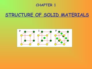
- 42. Physical Parameters for Crystal Structure (i)Number of Atoms per Unit Cell Number of atoms per unit cell determines how closely the solid is packed and is given by N = Nc/8 + Nf/2 + Ni here Nc is the number of corner atoms, Nf the number of face centred atoms and Ni the number of body centred atoms(see Fig.). For SC crystal : In a SC crystal, there are 8 atoms only, each at one corner. Each atom is shared by 8 unit cells. Therefore, we have N = Nc/8 = 8/8 = 1 For BCC crystal :N = Nc/8 + Nf/2 + Ni = 8/8 + 0 + 1 = 2 For FCC crystal :N = Nc/8 + Nf/2 + Ni = 8/8 + 6/2 + 0 = 4
- 43. (ii) Coordination Number (CN) In a crystal, the number of nearest neighbours of the same type and at equal distances from the given atom is called coordination number. For SC : The corner atoms are the nearest neighbours of each other. Here CN = 6(see Fig.) which is a group of 8 unit cell and atom at the centre has six corner atoms as its nearest neighbours).
- 44. For BCC : In this case all the corner atoms are at equal distances from the body centered atom. Hence CN = 8. For FCC : Here the nearest neighbours of any corner atom are the face centered atoms of the surrounding unit cells. Now for any corner atom there are 4 face centered atoms in each plane and there are three such planes. Therefore, CN = 12.
- 45. (iii) Atomic Radius and Nearest Neighbour Distance (NND) In a crystal the atoms are assumed to be spheres in contact. Now atomic radius is defined as half the distance between the nearest neighbours in a crystal of pure element, i.e., the distance between the centres of neighbouring atoms. For SC : In a SC structure, corner atoms are the nearest neighbours and are in touch with each other. If the side of the unit cell is ‘a’ and ‘r’ be the radius , then 2r = a or r = a/2 Now Nearest Neighbour Distance(NND) is given by 2r Therefore, NND = 2r = a
- 46. For FCC : r = √2 a/4 NND = a/√2
- 47. For BCC : r = √3 a/4 NND = √3 a/2.
- 48. (iv) Atomic Packing Fraction (or Factor) (APF) It is defined as the ratio of the volume of the atoms occupying the unit cell to the volume of the unit cell. It is also called relative packing density. APF = Volume occupied by the atoms in a unit cell / Volume of the unit cell. SC Crystal : No. of atoms/unit cell = 1 Volume of one atom = 4/3 πr3 Side of the unit cell = a = 2r Volume of the unit cell = a3 APF = = = π/6 = 0.52 = 52%. BCC Crystal : No. of atoms/unit cell = 2 Volume of two atoms = 2x4/3 πr3 Side of the unit cell = a = 4r/√3 Volume of the unit cell = a3 APF = = = √3π/8 = 0.68 = 68%. FCC Crystal : No. of atoms/unit cell = 4 Volume of four atoms = 4x4/3 πr3 Side of the unit cell = a = 4r/√2 Volume of the unit cell = a3 APF = = = √2π/6 = 0.74 = 74%.
- 49. Hexagonal Close Packed Structure (hcp) In a closed packed structure the constituent atoms are so arranged as to occupy minimum possible volume. One of the most effective arrangement for packing of atoms in a plane is shown in Fig. Here identical spheres(atoms) are arranged in a single close packed layer(say ‘A’) with each sphere touching six other spheres in a plane. This layer then assumes hexagonal shape. A second layer can now be added over this by placing spheres in the hollows ‘B’ which are formed by three spheres in the bottom layer. Now in the third layer the spheres are placed directly over the spheres of first layer, i.e., ‘A’. In this case the stacking is AB AB AB …, and the resulting three- dimensional structure is termed as hexagonal closed packed (hcp) as shown in Fig.
- 53. A B + HCP = A + Note: Atoms are coloured differently but are the same HCP Shown displaced for clarity Unit cell of HCP (Rhombic prism)
- 56. ( ) aaaah ×=×−=−= 4 3 4 1 1 2 2 2 aahx ×=××=×= 3 1 4 3 3 2 3 2 aaaxa c ×=−=−= 3 2 3 1 2 2222 633.1 3 8 == a c c/a Ratio of HCP: h = height of the equilateral triangle a = lattice constant Distance x from an atom to the middle of the triangle: Characteristics of HCP Coordination No. = 12 Number of atoms per unit cell = 6
- 58. DEFECTS IN SOLIDS No real crystal is perfect. Real crystals feature defects or irregularities in their ideal arrangements and it is these defects that critically determine many of the electrical and mechanical properties of real materials. Ideally a perfect crystal is the one in which atoms are arranged in perfectly regular manner in all directions. The deviations of crystals from their perfect periodicity are called defects or imperfections. These imperfections can be of different types such as: point defects (zero–dimensional defects), line defects (one–dimensional) defects over a surface or a plane (two–dimensional) and volume defects (three–dimensional).
- 59. A point defect is a very localized imperfection in the regularity of a lattice and it does not spread over more than one or two lattice spacings. These defects are observed in metallic crystals(vacancies, substitutional impurity and interstitials) as well as in ionic crystals(Schottky and Frenkel) and are discussed here in brief. Vacancies The absence of an atom or ion from a normally occupied site in a crystal is called a vacancy(see Fig.) Substitutional Impurity In this kind of defect, a foreign atom occupy a regular site in the crystal structure(see Fig.), i.e., .substitutional atom replaces the host atom from its position. For example, when a pure semiconductor crystal of Silicon or Germanium is doped with a trivalent or pentavalent impurity, we call it a substitutional impurity. Point Defects
- 60. Interstitial Impurity An interstitial is an atom or ion which can be inserted into the voids between the regularly occupied sites. In a closed packed arrangement of atoms the packing fraction is generally less than one. Therefore an extra atom, of smaller size than the parent atom, can enter the interstitial space without disturbing the regularly positioned atoms. Such an extra impure atom is called interstitial impurity while an extra atom in an interstitial position is called self – interstitial atom,as shown in Fig. If the size of the extra atom is not small then it will produce atomic distortion.
- 63. Schottky Defect In a metal, a vacancy is created if an atom is missing from its lattice position. In ionic crystals, a cation – anion pair will be missing from the respective lattice sites, as shown in Fig. Creation of such a pair, of one cation vacancy together with one anion vacancy, is called Schottky defect. Thus the interior of the ionic crystals remain electrically neutral. Frenkel Defect When an atom or ion leaves its normal position or site and is found to occupy another position in the interstice we get a Frenkel defect. Thus, in this case, two imperfections are created – an interstitial and a vacancy as shown in Fig. Normally anion leaves its parent site and occupy the interstitial space. These defects are dominant in open structures such as silver halides. Also a Frenkel defect does not affect the electrical neutrality of a crystal.
- 64. Missing anion site Missing cation site Missing cation site Interstitial ion (a) Shottkey defect (b) Frenkel defect Cation Anion
- 66. Concentration of Schottky Defects Consider a pure crystal composed of equal numbers of positively and negatively charged ions. Let us assume that it contains N ions and n Schottky defects, i.e., n – cation vacancies and n – anion vacancies. Now, for a crystal, Helmholtz free energy F is defined as F = U – T.S …(1) here U is the internal energy, S is the entropy(the measure of disorder in a system) and T is the temperature. Let E is energy required to produce a pair of vacancies in the interior of a crystal. Then the increase in internal energy, when n – vacancies are formed, is U = nE …(2)
- 67. As the number of defects increases, the number of possible arrangements also increases thereby increasing the entropy of the system. The entropy increase, when n – vacancies are formed, is given by S = k log W …(3) where W is the number of distinct ways in which ‘n’ indistinguishable vacancies can be produced (or distributed) along N total number of sites per mole and is given by − == !)!( ! nnN N CW n N …(4) and the different ways in which n vacancy pairs(since the numbers of cation and anion vacancies are equal) can be produced, is simply obtained by squaring the above expression, i.e., 2 !)!( ! − =×= nnN N CCW n N n N …(5)
- 68. using equations (2), (3) and (5) in equation (1) we have 2 !)!( ! log − ⋅−=−= nnN N kTEnTSUF …(6) Using Stirling’s approximation for x >>1, we can write xxxx −= log!log [ ]!log)!(log!log2 !)!( ! log2 !)!( ! log 2 nnNN nnN N nnN N −−−= − = − [ ]nnnnNnNnNNNN +−−+−−−−= log)()log()(log2 [ ]nnnNnNNN log)log()(log2 −−−−= Using this in equation (6), we have [ ]nnnNnNNNkTnEF log)log()(log2 −−−−−= …(7)
- 69. Although internal energy increases, the effect of increase in entropy finally results in the decrease of free energy(see equation 1). When addition of more defects no longer lowers the value of free energy F, the equilibrium state of minimum(or constant) free energy has reached for a given temperature. At this stage 0= Tdn dF ( )[ ] 0log)log()(log2 =−−−−− nnnNnNNNkTnE dn d …(8) Solving the differentials : ( ) EEnE dn d =⋅= 1 …(i) [ ]nnnNnNNN dn d log)log()(log −−−− ( ) ( ) ( ) ( ) ⋅+⋅− −⋅−+ − −× −−= 1log 1 1log 11 0 n n nnN nN nN
- 70. ( )( ) ( ) ( ) { } +− −⋅−+ − −− −= nnN nN nN log11log 1 ( ) nnN log1log1 −−−++= ( ) nnN loglog −−= …(ii) Therefore, using these differentials (i) and (ii), equation (8) becomes [ ] 0log)log(2 =−−−= ∂ ∂ nnNTkE n F T …(9) ⇒ − = n nN kTE log2 ⇒ ⇒ kT E n nN 2 log = − kT E e n nN 2 = −
- 71. As the number of vacancies in a crystal is much smaller than the number of ions, i.e., n<< N and (N – n) ≈ N, therefore, above equation becomes kT E e n N 2 = kT E kT E e eN n 2 2 1 − == kT E Nen 2 − = = concentration of Schottky defects …(10)⇒ ⇒
- 72. Therefore, we can conclude that the number of Schottky defects in a crystal depends upon : • the total number of ion – pairs(N), • the average energy(E) required to produce a Schottky defect and • temperature(T). It is also found that the fraction of Schottky defects increases exponentially with increasing temperature and a certain amount of defects are always present at all temperatures above the absolute zero.
- 73. Concentration of Frenkel Defects For concentration of Frenkel defects, let us again consider a pure crystal consisting of equal numbers of positively and negatively charged ions. Consider that it contains a total of N ions and n Frenkel defects, i.e., n – cation / anion vacancies and n – interstitial ions in its interior. Now Helmholtz free energy F is defined as F = U – T.S …(1) here U is the internal energy, S is the entropy and T is the temperature. If Ei as the energy required to create a vacancy, i.e., to displace a cation from its regular position to an interstitial occupation, then increase in internal energy for n Frenkel defects is given by U = nEi …(2)
- 74. The entropy increase is given by S = k log W …(3) where W is the number of distinct ways in which ‘n’ Frenkel defects can be produced and is given by …(4) …(5) !)!( ! !)!( ! nnN N nnN N W i i − ⋅ − = here Ni is the number of interstitial positions in the crystal. − ⋅ − = !)!( ! !)!( ! log nnN N nnN N kS i i ∴ Now Helmholtz free energy(equation 1) becomes − ⋅ − −= !)!( ! !)!( ! log nnN N nnN N TkEnF i i i …(6)
- 75. Solving the factorial terms by using Strirling’s approximation, for x>>1 xxxx −= log!log we get −−−− −−−+ = − ⋅ − nnnNnN nNnNNNNN nnN N nnN N ii ii i i log2)log()( )log()(loglog !)!( ! !)!( ! log Putting this value in equation (6), we have −−−− −−−+ −= nnnNnN nNnNNNNN kTnEF ii ii i log2)log()( )log()(loglog …(7) When equilibrium is reached, the free energy is minimum, i.e., at equilibrium 0= Tdn dF …(8)
- 76. ( ) 0 log2)log()( )log()(loglog = −−−− −−−+ − nnnNnN nNnNNNNN dn d kTnE dn d ii ii i⇒ solving the differentials, we will get 0 ))(( log 2 = −− −= n nNnN TkE dn dF i i T …(9) …(10) As N >> n and Ni >> n, therefore, the above equation becomes nNN n NN kT E i ii log2)log(log 2 −= = kT E NNn i i 2 )log( 2 1 log −= kT E i i eNNn 22 1 )( − = = concentration of Frenkel defects
- 77. Therefore, in this case we find that the number of Frenkel defects in a crystal depends upon : (i) the product (NNi)1/2 , (ii) the average energy Ei and (iii) temperature (T). It can also be concluded that number of defects in a crystal are found to increase exponentially as its temperature rises. It is also found that certain amount of defects are always present in a crystal at all temperatures above absolute zero.