SlideShare una empresa de Scribd logo
1 de 18
Least Material Condition is fairly rare in geometric dimensioning and tolerancing.
There are only a few reasons why a LMC should be called. The most common
reason for calling it would be that you have a hole or other internal feature that is
very close to the edge of a part. If you call LMC with true position in figure 2 below
– you would be specifying that if the hole is at its largest size, it can only vary by as
much as the true position tolerance. However if the hole is smaller than its Least
Material Condition, you can apply a bonus tolerance to the part, because now the
true center of the hole can be closer to the edge, without minimizing the thickness
of the material.
Least material condition should only
be used when absolutely needed
Least Material Condition is really only
used to ensure there is enough
thickness between the edge and the
inside of the hole.
Feature Size
Position Tolerance
Allowed
2.500 .010
2.501 .010
2.502 .010
2.503 .010
2.504 .010
2.505 .010
2.506 .010
2.507 .010
2.508 .010
2.509 .010
2.510 .010
Here we have a Ø2.500 +.010/-.000 hole and its position tolerance is Ø.010. Each of these
conditions described above will have a different effect on the allowed position of this hole.
RFS: When a tolerance is implied at RFS, the specified tolerance is independent of the
feature's actual size. This means that no matter what the actual hole diameter ends up
being, the applied tolerance is always the stated value. In this case .010. Here's a table to
show what that means:
Feature Size
Position Tolerance
Allowed
2.500 .010
2.501 .011
2.502 .012
2.503 .013
2.504 .014
2.505 .015
2.506 .016
2.507 .017
2.508 .018
2.509 .019
2.510 .020
MMC: The stated tolerance applies at the MMC size of the feature, and additional
tolerance is gained as the feature departs from the MMC size. This means that at the MMC
(smallest diameter), the stated tolerance is applied. As the holes gets larger the position
gains additional tolerance. Here's a table showing that:
Feature Size
Position Tolerance
Allowed
2.500 .000
2.501 .001
2.502 .002
2.503 .003
2.504 .004
2.505 .005
2.506 .006
2.507 .007
2.508 .008
2.509 .009
2.510 .010
Zero @ MMC: This is very similar to MMC, except that the stated tolerance is zero. At
the MMC feature size, the allowed positional tolerance is zero. As the feature departs
from the MMC, additional tolerance is gained. Here's a table showing the effect:
Feature Size
Position
Tolerance
Allowed
2.510 .010
2.509 .011
2.508 .012
2.507 .013
2.506 .014
2.505 .015
2.504 .016
2.503 .017
2.502 .018
2.501 .019
2.500 .020
LMC: This is the exact opposite of MMC. The stated tolerance applies at the feature's
LMC (largest diameter) and as the feature departs from the LMC more tolerance is
allowed. Here's a table showing that effect:
Now that the effect of each modifier has been shown, how do you
decide which one (if any) to use?
RFS: Used when locating a press fit pin or shaft.
MMC: When the hole is being used in a clearance application.
Zero @ MMC: Can be used in place of MMC.
LMC: Used in a locational application.
Important note: LMC is not commonly used. RFS is usually the best
option when using a feature to locate another.
When a geometric characteristic is specified with MMC, the geometric
tolerance may have a bonus tolerance when its FOS is approaching to
its Least Material Condition (LMC).
From the table shown in this figure, if the diameter of a part is measured at
1.02, which is the MMC, there is no bonus tolerance and the Position
Tolerance remains at 0.05. However, when the diameter is measured at 0.98,
which is the LMC, the bonus tolerance is equal to 0.04. Therefore, the total
Position Tolerance in this case increases to 0.09. Because of the bonus
tolerances, application of MMC can be easily found in most GD&T design
drawings.
When a geometric tolerance is specified
with LMC, the geometric tolerance may
have a bonus tolerance when its FOS is
approaching to its MMC.
From the table shown in this figure, when the diameter of a part is measured
at 1.02, which is the MMC, there is a bonus tolerance and the total Position
Tolerance increases to 0.09. However, when the diameter of a part is
measured at 0.98, which is the LMC, there is no bonus tolerance. LMC is
particularly applied to guarantee a larger minimum thickness in a thin part
than MMC.
Unlike MMC and LMC, Regardless of Feature Size gives no additional
geometric tolerance. The concept of RFS has been used prior to the
introduction of MMC and LMC principles. Figure 4 shows a design drawing
using an RFS Position Tolerance. Since there is no modifier added to the
Position Tolerance, according to Rule 26, the Position Tolerance is an RFS.
From the table shown in this figure, the Position Tolerance remains the
same regardless the variations on the FOS.
According to ASME14.5M1,6,7, Rule 1 states:
“Where only a tolerance of size is specified, the limits of size of an individual feature
prescribe the extent to which variations in its form – as well as in its size- are allowed.”
This definition includes two main components: (1) the envelope-size principle and (2) the
Form Tolerance allowed when a FOS departs from MMC. For example, Figure 1 shows
the diameter of a shaft in an engineering drawing. Figure 2 shows the envelope-size
principle, which states that the FOS is applicable not only to the size at each cross
section,
but also to the whole length of the feature. Figure 3 shows that, when the FOS departs
from its MMC, a Form Tolerance will be allowed. Therefore, when the FOS is at its
MMC, the part must have a perfect form.
Figure 1
Figure 2
Figure 3
The envelope-size principle
An allowable Form Tolerance for a part
when its diameter departs from MMC
According to ASME14.5M, Rule 2 states:
“For all applicable geometric tolerances, Regardless of Feature of
Size (RFS) applies with respect to the individual tolerance, datum
reference, or both, where no modifying symbol is specified.
Maximum Material Condition M, or Least Material Condition L, must
be specified on drawing where it is required.”
The rule can be applied to the design drawing shown in Figure. Due to
the nature of the control, RFS can be applicable at most of geometric
characteristics except at three Form Tolerances: Flatness, Circularity,
and Cylindricity. While Rule 2 seems clear and simple, several geometric
characteristics without m or l are still non RFS. These exceptions cause
confusions to the students when taking this class.
Cases in Which Rule 2 Applies
There are two cases in which Rule 2 is applicable.
The first case is when a geometric characteristic is applied with an FOS,
and the second case is
when a geometric characteristic is applied with a feature.
RFS when Geometric Characteristics applied with FOS
Geometric characteristics which are allowed to specify with FOS are
Straightness, Perpendicularity, Parallelism, Angularity, Position, Circular Runout,
Total Runout, Concentricity, and Symmetry, are RFS.
RFS with Straightness Figure shows that a Straightness
Tolerance is specified with an FOS.
The Straightness is used to control
the central axis of the shaft.
As shown from the table, the
Straightness Tolerance remains the
same regardless the change on the
FOS of the diameter.
Therefore, this is an RFS. In the
Form Tolerances, RFS is only
applicable to Straightness.
Fig : RFS Straightness control on the
central axis of a shaft
RFS with Orientation Tolerances
Figure shows that a Perpendicularity Tolerance is specified with an FOS.
Similar to the RFS with Straightness, the Perpendicularity is used to
control the central axis of the hole.
As shown from the table, the Perpendicularity Tolerance remains the
same regardless the change on the FOS of the diameter. Therefore, this
is an RFS. The same situation can be applied to other Orientation
Tolerances.
RFS with Perpendicularity
RFS with Position Tolerances
As given in Table 1, Location Tolerances includes Position, Concentricity, and
Symmetry Tolerances. Figure shows a Position Tolerance with RFS. The
Position Tolerance zone of φ0.015 is used to control the central location of the
hole. The boxed dimensions in this drawing are called basic dimensions, which
can be described as the theoretically exact dimensions. As shown from the
table, the Position Tolerance remains the same regardless the variations on
the FOS of the diameter. The same rule can be applied to other Position
Tolerances, such as Concentricity and Symmetry.
From the examples shown above, when a geometric characteristic is specified
with an FOS, the tolerance will be an RFS
RFS with Runout - FOS
Figure shows a Runout Tolerance with RFS. The tolerance zone of 0.015” is used
to control the Total Runout on the outer surface of φ4.500”. Therefore, when
compared to tolerance zone in Figure 10, there is no φ in front of 0.015”. The
datum axis is at the center axis of φ2.000”. As shown from the table, the Total
Runout remains the same regardless the variations on the FOS of the diameter.
RFS with Runout when applied with a feature
Apart from the examples given, there is only one RFS example when the
geometric characteristic is applied with a feature. The geometric characteristic is
a Runout control, which is shown in Figure 12. The circular runout of 0.06 is to
control the wobble of the Surface B, and is measured when the surface is
rotated around the datum axis A. Based on the nature of the runout
measurement, the Circular Runout remains the same regardless the variations
on the FOS (2.25”). Therefore, this is also an RFS.
Understanding LMC and bonus tolerances in GD&T

Más contenido relacionado

Similar a Understanding LMC and bonus tolerances in GD&T

Limits, Fits & Tolerances
Limits, Fits & TolerancesLimits, Fits & Tolerances
Limits, Fits & TolerancesAspirations
 
Limits, Fits & Tolerances
Limits, Fits & TolerancesLimits, Fits & Tolerances
Limits, Fits & TolerancesAkash Patel
 
Engineering Metrology : System of Limits and Fits
Engineering Metrology : System of Limits and FitsEngineering Metrology : System of Limits and Fits
Engineering Metrology : System of Limits and FitsUnimetry Technology
 
Structural analysis & design of troughed floors
Structural analysis & design of troughed floorsStructural analysis & design of troughed floors
Structural analysis & design of troughed floorsVictor Omotoriogun
 
4. Limits ,Tolerance and Fits.pptx
4. Limits ,Tolerance and Fits.pptx4. Limits ,Tolerance and Fits.pptx
4. Limits ,Tolerance and Fits.pptxtilahunyeshiye
 
Geometric Dimensioning & Tolerancing
Geometric Dimensioning & TolerancingGeometric Dimensioning & Tolerancing
Geometric Dimensioning & TolerancingAnubhav Singh
 
GDT CHAPTER 1- Overview and introduction.ppt
GDT CHAPTER 1- Overview and introduction.pptGDT CHAPTER 1- Overview and introduction.ppt
GDT CHAPTER 1- Overview and introduction.pptsyisyi87
 
Gd&T Presentation1111
Gd&T Presentation1111Gd&T Presentation1111
Gd&T Presentation1111zuhaib ansar
 
Gd&t introductory presentation
Gd&t introductory presentationGd&t introductory presentation
Gd&t introductory presentationSimranjit Singh
 
Tolerance and Fits
Tolerance and FitsTolerance and Fits
Tolerance and Fitsnmahi96
 
Unit_4_Design Agains Fluctuation load.ppt
Unit_4_Design Agains Fluctuation load.pptUnit_4_Design Agains Fluctuation load.ppt
Unit_4_Design Agains Fluctuation load.pptDrSomnathKolgiri
 
Ipec limits fits
Ipec limits fitsIpec limits fits
Ipec limits fitsManoj Yadav
 
Unit 3 design against fluctuation load
Unit 3 design against fluctuation loadUnit 3 design against fluctuation load
Unit 3 design against fluctuation loadSomnath Kolgiri
 
Determination of Critical Flaw Size in Gun Launched 40mm Grenade
Determination of Critical Flaw Size in Gun Launched 40mm GrenadeDetermination of Critical Flaw Size in Gun Launched 40mm Grenade
Determination of Critical Flaw Size in Gun Launched 40mm GrenadeSIMULIA
 
Geometrical Dimensioning and Tolerancing
Geometrical Dimensioning and TolerancingGeometrical Dimensioning and Tolerancing
Geometrical Dimensioning and Tolerancingssuser5670d6
 

Similar a Understanding LMC and bonus tolerances in GD&T (20)

Limits, Fits & Tolerances
Limits, Fits & TolerancesLimits, Fits & Tolerances
Limits, Fits & Tolerances
 
UNIT-1 CHAPTER-2.pdf
UNIT-1 CHAPTER-2.pdfUNIT-1 CHAPTER-2.pdf
UNIT-1 CHAPTER-2.pdf
 
Limits, Fits & Tolerances
Limits, Fits & TolerancesLimits, Fits & Tolerances
Limits, Fits & Tolerances
 
Engineering Metrology : System of Limits and Fits
Engineering Metrology : System of Limits and FitsEngineering Metrology : System of Limits and Fits
Engineering Metrology : System of Limits and Fits
 
Structural analysis & design of troughed floors
Structural analysis & design of troughed floorsStructural analysis & design of troughed floors
Structural analysis & design of troughed floors
 
4. Limits ,Tolerance and Fits.pptx
4. Limits ,Tolerance and Fits.pptx4. Limits ,Tolerance and Fits.pptx
4. Limits ,Tolerance and Fits.pptx
 
Geometric Dimensioning & Tolerancing
Geometric Dimensioning & TolerancingGeometric Dimensioning & Tolerancing
Geometric Dimensioning & Tolerancing
 
GDT CHAPTER 1- Overview and introduction.ppt
GDT CHAPTER 1- Overview and introduction.pptGDT CHAPTER 1- Overview and introduction.ppt
GDT CHAPTER 1- Overview and introduction.ppt
 
5 SLS Requierments.pptx
5 SLS Requierments.pptx5 SLS Requierments.pptx
5 SLS Requierments.pptx
 
Geometric dimensioning and tolerancing
Geometric dimensioning and tolerancingGeometric dimensioning and tolerancing
Geometric dimensioning and tolerancing
 
Gd&T Presentation1111
Gd&T Presentation1111Gd&T Presentation1111
Gd&T Presentation1111
 
Gd&t introductory presentation
Gd&t introductory presentationGd&t introductory presentation
Gd&t introductory presentation
 
Tolerance and Fits
Tolerance and FitsTolerance and Fits
Tolerance and Fits
 
Unit_4_Design Agains Fluctuation load.ppt
Unit_4_Design Agains Fluctuation load.pptUnit_4_Design Agains Fluctuation load.ppt
Unit_4_Design Agains Fluctuation load.ppt
 
Ipec limits fits
Ipec limits fitsIpec limits fits
Ipec limits fits
 
Unit 3 design against fluctuation load
Unit 3 design against fluctuation loadUnit 3 design against fluctuation load
Unit 3 design against fluctuation load
 
Fits, tolerance and surface roughness
Fits, tolerance and surface roughnessFits, tolerance and surface roughness
Fits, tolerance and surface roughness
 
Ak26230233
Ak26230233Ak26230233
Ak26230233
 
Determination of Critical Flaw Size in Gun Launched 40mm Grenade
Determination of Critical Flaw Size in Gun Launched 40mm GrenadeDetermination of Critical Flaw Size in Gun Launched 40mm Grenade
Determination of Critical Flaw Size in Gun Launched 40mm Grenade
 
Geometrical Dimensioning and Tolerancing
Geometrical Dimensioning and TolerancingGeometrical Dimensioning and Tolerancing
Geometrical Dimensioning and Tolerancing
 

Último

MANUFACTURING PROCESS-II UNIT-2 LATHE MACHINE
MANUFACTURING PROCESS-II UNIT-2 LATHE MACHINEMANUFACTURING PROCESS-II UNIT-2 LATHE MACHINE
MANUFACTURING PROCESS-II UNIT-2 LATHE MACHINESIVASHANKAR N
 
Booking open Available Pune Call Girls Koregaon Park 6297143586 Call Hot Ind...
Booking open Available Pune Call Girls Koregaon Park  6297143586 Call Hot Ind...Booking open Available Pune Call Girls Koregaon Park  6297143586 Call Hot Ind...
Booking open Available Pune Call Girls Koregaon Park 6297143586 Call Hot Ind...Call Girls in Nagpur High Profile
 
result management system report for college project
result management system report for college projectresult management system report for college project
result management system report for college projectTonystark477637
 
UNIT - IV - Air Compressors and its Performance
UNIT - IV - Air Compressors and its PerformanceUNIT - IV - Air Compressors and its Performance
UNIT - IV - Air Compressors and its Performancesivaprakash250
 
College Call Girls Nashik Nehal 7001305949 Independent Escort Service Nashik
College Call Girls Nashik Nehal 7001305949 Independent Escort Service NashikCollege Call Girls Nashik Nehal 7001305949 Independent Escort Service Nashik
College Call Girls Nashik Nehal 7001305949 Independent Escort Service NashikCall Girls in Nagpur High Profile
 
Microscopic Analysis of Ceramic Materials.pptx
Microscopic Analysis of Ceramic Materials.pptxMicroscopic Analysis of Ceramic Materials.pptx
Microscopic Analysis of Ceramic Materials.pptxpurnimasatapathy1234
 
(MEERA) Dapodi Call Girls Just Call 7001035870 [ Cash on Delivery ] Pune Escorts
(MEERA) Dapodi Call Girls Just Call 7001035870 [ Cash on Delivery ] Pune Escorts(MEERA) Dapodi Call Girls Just Call 7001035870 [ Cash on Delivery ] Pune Escorts
(MEERA) Dapodi Call Girls Just Call 7001035870 [ Cash on Delivery ] Pune Escortsranjana rawat
 
APPLICATIONS-AC/DC DRIVES-OPERATING CHARACTERISTICS
APPLICATIONS-AC/DC DRIVES-OPERATING CHARACTERISTICSAPPLICATIONS-AC/DC DRIVES-OPERATING CHARACTERISTICS
APPLICATIONS-AC/DC DRIVES-OPERATING CHARACTERISTICSKurinjimalarL3
 
OSVC_Meta-Data based Simulation Automation to overcome Verification Challenge...
OSVC_Meta-Data based Simulation Automation to overcome Verification Challenge...OSVC_Meta-Data based Simulation Automation to overcome Verification Challenge...
OSVC_Meta-Data based Simulation Automation to overcome Verification Challenge...Soham Mondal
 
KubeKraft presentation @CloudNativeHooghly
KubeKraft presentation @CloudNativeHooghlyKubeKraft presentation @CloudNativeHooghly
KubeKraft presentation @CloudNativeHooghlysanyuktamishra911
 
Introduction and different types of Ethernet.pptx
Introduction and different types of Ethernet.pptxIntroduction and different types of Ethernet.pptx
Introduction and different types of Ethernet.pptxupamatechverse
 
MANUFACTURING PROCESS-II UNIT-5 NC MACHINE TOOLS
MANUFACTURING PROCESS-II UNIT-5 NC MACHINE TOOLSMANUFACTURING PROCESS-II UNIT-5 NC MACHINE TOOLS
MANUFACTURING PROCESS-II UNIT-5 NC MACHINE TOOLSSIVASHANKAR N
 
Software Development Life Cycle By Team Orange (Dept. of Pharmacy)
Software Development Life Cycle By  Team Orange (Dept. of Pharmacy)Software Development Life Cycle By  Team Orange (Dept. of Pharmacy)
Software Development Life Cycle By Team Orange (Dept. of Pharmacy)Suman Mia
 
IMPLICATIONS OF THE ABOVE HOLISTIC UNDERSTANDING OF HARMONY ON PROFESSIONAL E...
IMPLICATIONS OF THE ABOVE HOLISTIC UNDERSTANDING OF HARMONY ON PROFESSIONAL E...IMPLICATIONS OF THE ABOVE HOLISTIC UNDERSTANDING OF HARMONY ON PROFESSIONAL E...
IMPLICATIONS OF THE ABOVE HOLISTIC UNDERSTANDING OF HARMONY ON PROFESSIONAL E...RajaP95
 
Extrusion Processes and Their Limitations
Extrusion Processes and Their LimitationsExtrusion Processes and Their Limitations
Extrusion Processes and Their Limitations120cr0395
 
Call for Papers - Educational Administration: Theory and Practice, E-ISSN: 21...
Call for Papers - Educational Administration: Theory and Practice, E-ISSN: 21...Call for Papers - Educational Administration: Theory and Practice, E-ISSN: 21...
Call for Papers - Educational Administration: Theory and Practice, E-ISSN: 21...Christo Ananth
 
Call for Papers - African Journal of Biological Sciences, E-ISSN: 2663-2187, ...
Call for Papers - African Journal of Biological Sciences, E-ISSN: 2663-2187, ...Call for Papers - African Journal of Biological Sciences, E-ISSN: 2663-2187, ...
Call for Papers - African Journal of Biological Sciences, E-ISSN: 2663-2187, ...Christo Ananth
 
UNIT-III FMM. DIMENSIONAL ANALYSIS
UNIT-III FMM.        DIMENSIONAL ANALYSISUNIT-III FMM.        DIMENSIONAL ANALYSIS
UNIT-III FMM. DIMENSIONAL ANALYSISrknatarajan
 
Processing & Properties of Floor and Wall Tiles.pptx
Processing & Properties of Floor and Wall Tiles.pptxProcessing & Properties of Floor and Wall Tiles.pptx
Processing & Properties of Floor and Wall Tiles.pptxpranjaldaimarysona
 

Último (20)

MANUFACTURING PROCESS-II UNIT-2 LATHE MACHINE
MANUFACTURING PROCESS-II UNIT-2 LATHE MACHINEMANUFACTURING PROCESS-II UNIT-2 LATHE MACHINE
MANUFACTURING PROCESS-II UNIT-2 LATHE MACHINE
 
Booking open Available Pune Call Girls Koregaon Park 6297143586 Call Hot Ind...
Booking open Available Pune Call Girls Koregaon Park  6297143586 Call Hot Ind...Booking open Available Pune Call Girls Koregaon Park  6297143586 Call Hot Ind...
Booking open Available Pune Call Girls Koregaon Park 6297143586 Call Hot Ind...
 
result management system report for college project
result management system report for college projectresult management system report for college project
result management system report for college project
 
UNIT - IV - Air Compressors and its Performance
UNIT - IV - Air Compressors and its PerformanceUNIT - IV - Air Compressors and its Performance
UNIT - IV - Air Compressors and its Performance
 
College Call Girls Nashik Nehal 7001305949 Independent Escort Service Nashik
College Call Girls Nashik Nehal 7001305949 Independent Escort Service NashikCollege Call Girls Nashik Nehal 7001305949 Independent Escort Service Nashik
College Call Girls Nashik Nehal 7001305949 Independent Escort Service Nashik
 
Microscopic Analysis of Ceramic Materials.pptx
Microscopic Analysis of Ceramic Materials.pptxMicroscopic Analysis of Ceramic Materials.pptx
Microscopic Analysis of Ceramic Materials.pptx
 
(MEERA) Dapodi Call Girls Just Call 7001035870 [ Cash on Delivery ] Pune Escorts
(MEERA) Dapodi Call Girls Just Call 7001035870 [ Cash on Delivery ] Pune Escorts(MEERA) Dapodi Call Girls Just Call 7001035870 [ Cash on Delivery ] Pune Escorts
(MEERA) Dapodi Call Girls Just Call 7001035870 [ Cash on Delivery ] Pune Escorts
 
APPLICATIONS-AC/DC DRIVES-OPERATING CHARACTERISTICS
APPLICATIONS-AC/DC DRIVES-OPERATING CHARACTERISTICSAPPLICATIONS-AC/DC DRIVES-OPERATING CHARACTERISTICS
APPLICATIONS-AC/DC DRIVES-OPERATING CHARACTERISTICS
 
OSVC_Meta-Data based Simulation Automation to overcome Verification Challenge...
OSVC_Meta-Data based Simulation Automation to overcome Verification Challenge...OSVC_Meta-Data based Simulation Automation to overcome Verification Challenge...
OSVC_Meta-Data based Simulation Automation to overcome Verification Challenge...
 
KubeKraft presentation @CloudNativeHooghly
KubeKraft presentation @CloudNativeHooghlyKubeKraft presentation @CloudNativeHooghly
KubeKraft presentation @CloudNativeHooghly
 
Introduction and different types of Ethernet.pptx
Introduction and different types of Ethernet.pptxIntroduction and different types of Ethernet.pptx
Introduction and different types of Ethernet.pptx
 
DJARUM4D - SLOT GACOR ONLINE | SLOT DEMO ONLINE
DJARUM4D - SLOT GACOR ONLINE | SLOT DEMO ONLINEDJARUM4D - SLOT GACOR ONLINE | SLOT DEMO ONLINE
DJARUM4D - SLOT GACOR ONLINE | SLOT DEMO ONLINE
 
MANUFACTURING PROCESS-II UNIT-5 NC MACHINE TOOLS
MANUFACTURING PROCESS-II UNIT-5 NC MACHINE TOOLSMANUFACTURING PROCESS-II UNIT-5 NC MACHINE TOOLS
MANUFACTURING PROCESS-II UNIT-5 NC MACHINE TOOLS
 
Software Development Life Cycle By Team Orange (Dept. of Pharmacy)
Software Development Life Cycle By  Team Orange (Dept. of Pharmacy)Software Development Life Cycle By  Team Orange (Dept. of Pharmacy)
Software Development Life Cycle By Team Orange (Dept. of Pharmacy)
 
IMPLICATIONS OF THE ABOVE HOLISTIC UNDERSTANDING OF HARMONY ON PROFESSIONAL E...
IMPLICATIONS OF THE ABOVE HOLISTIC UNDERSTANDING OF HARMONY ON PROFESSIONAL E...IMPLICATIONS OF THE ABOVE HOLISTIC UNDERSTANDING OF HARMONY ON PROFESSIONAL E...
IMPLICATIONS OF THE ABOVE HOLISTIC UNDERSTANDING OF HARMONY ON PROFESSIONAL E...
 
Extrusion Processes and Their Limitations
Extrusion Processes and Their LimitationsExtrusion Processes and Their Limitations
Extrusion Processes and Their Limitations
 
Call for Papers - Educational Administration: Theory and Practice, E-ISSN: 21...
Call for Papers - Educational Administration: Theory and Practice, E-ISSN: 21...Call for Papers - Educational Administration: Theory and Practice, E-ISSN: 21...
Call for Papers - Educational Administration: Theory and Practice, E-ISSN: 21...
 
Call for Papers - African Journal of Biological Sciences, E-ISSN: 2663-2187, ...
Call for Papers - African Journal of Biological Sciences, E-ISSN: 2663-2187, ...Call for Papers - African Journal of Biological Sciences, E-ISSN: 2663-2187, ...
Call for Papers - African Journal of Biological Sciences, E-ISSN: 2663-2187, ...
 
UNIT-III FMM. DIMENSIONAL ANALYSIS
UNIT-III FMM.        DIMENSIONAL ANALYSISUNIT-III FMM.        DIMENSIONAL ANALYSIS
UNIT-III FMM. DIMENSIONAL ANALYSIS
 
Processing & Properties of Floor and Wall Tiles.pptx
Processing & Properties of Floor and Wall Tiles.pptxProcessing & Properties of Floor and Wall Tiles.pptx
Processing & Properties of Floor and Wall Tiles.pptx
 

Understanding LMC and bonus tolerances in GD&T

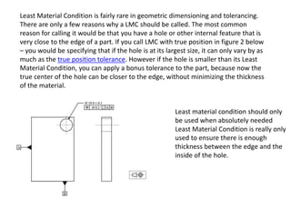
  • 1. Least Material Condition is fairly rare in geometric dimensioning and tolerancing. There are only a few reasons why a LMC should be called. The most common reason for calling it would be that you have a hole or other internal feature that is very close to the edge of a part. If you call LMC with true position in figure 2 below – you would be specifying that if the hole is at its largest size, it can only vary by as much as the true position tolerance. However if the hole is smaller than its Least Material Condition, you can apply a bonus tolerance to the part, because now the true center of the hole can be closer to the edge, without minimizing the thickness of the material. Least material condition should only be used when absolutely needed Least Material Condition is really only used to ensure there is enough thickness between the edge and the inside of the hole.
  • 2.
  • 3. Feature Size Position Tolerance Allowed 2.500 .010 2.501 .010 2.502 .010 2.503 .010 2.504 .010 2.505 .010 2.506 .010 2.507 .010 2.508 .010 2.509 .010 2.510 .010 Here we have a Ø2.500 +.010/-.000 hole and its position tolerance is Ø.010. Each of these conditions described above will have a different effect on the allowed position of this hole. RFS: When a tolerance is implied at RFS, the specified tolerance is independent of the feature's actual size. This means that no matter what the actual hole diameter ends up being, the applied tolerance is always the stated value. In this case .010. Here's a table to show what that means:
  • 4. Feature Size Position Tolerance Allowed 2.500 .010 2.501 .011 2.502 .012 2.503 .013 2.504 .014 2.505 .015 2.506 .016 2.507 .017 2.508 .018 2.509 .019 2.510 .020 MMC: The stated tolerance applies at the MMC size of the feature, and additional tolerance is gained as the feature departs from the MMC size. This means that at the MMC (smallest diameter), the stated tolerance is applied. As the holes gets larger the position gains additional tolerance. Here's a table showing that:
  • 5. Feature Size Position Tolerance Allowed 2.500 .000 2.501 .001 2.502 .002 2.503 .003 2.504 .004 2.505 .005 2.506 .006 2.507 .007 2.508 .008 2.509 .009 2.510 .010 Zero @ MMC: This is very similar to MMC, except that the stated tolerance is zero. At the MMC feature size, the allowed positional tolerance is zero. As the feature departs from the MMC, additional tolerance is gained. Here's a table showing the effect:
  • 6. Feature Size Position Tolerance Allowed 2.510 .010 2.509 .011 2.508 .012 2.507 .013 2.506 .014 2.505 .015 2.504 .016 2.503 .017 2.502 .018 2.501 .019 2.500 .020 LMC: This is the exact opposite of MMC. The stated tolerance applies at the feature's LMC (largest diameter) and as the feature departs from the LMC more tolerance is allowed. Here's a table showing that effect:
  • 7. Now that the effect of each modifier has been shown, how do you decide which one (if any) to use? RFS: Used when locating a press fit pin or shaft. MMC: When the hole is being used in a clearance application. Zero @ MMC: Can be used in place of MMC. LMC: Used in a locational application. Important note: LMC is not commonly used. RFS is usually the best option when using a feature to locate another.
  • 8. When a geometric characteristic is specified with MMC, the geometric tolerance may have a bonus tolerance when its FOS is approaching to its Least Material Condition (LMC). From the table shown in this figure, if the diameter of a part is measured at 1.02, which is the MMC, there is no bonus tolerance and the Position Tolerance remains at 0.05. However, when the diameter is measured at 0.98, which is the LMC, the bonus tolerance is equal to 0.04. Therefore, the total Position Tolerance in this case increases to 0.09. Because of the bonus tolerances, application of MMC can be easily found in most GD&T design drawings.
  • 9. When a geometric tolerance is specified with LMC, the geometric tolerance may have a bonus tolerance when its FOS is approaching to its MMC. From the table shown in this figure, when the diameter of a part is measured at 1.02, which is the MMC, there is a bonus tolerance and the total Position Tolerance increases to 0.09. However, when the diameter of a part is measured at 0.98, which is the LMC, there is no bonus tolerance. LMC is particularly applied to guarantee a larger minimum thickness in a thin part than MMC.
  • 10. Unlike MMC and LMC, Regardless of Feature Size gives no additional geometric tolerance. The concept of RFS has been used prior to the introduction of MMC and LMC principles. Figure 4 shows a design drawing using an RFS Position Tolerance. Since there is no modifier added to the Position Tolerance, according to Rule 26, the Position Tolerance is an RFS. From the table shown in this figure, the Position Tolerance remains the same regardless the variations on the FOS.
  • 11. According to ASME14.5M1,6,7, Rule 1 states: “Where only a tolerance of size is specified, the limits of size of an individual feature prescribe the extent to which variations in its form – as well as in its size- are allowed.” This definition includes two main components: (1) the envelope-size principle and (2) the Form Tolerance allowed when a FOS departs from MMC. For example, Figure 1 shows the diameter of a shaft in an engineering drawing. Figure 2 shows the envelope-size principle, which states that the FOS is applicable not only to the size at each cross section, but also to the whole length of the feature. Figure 3 shows that, when the FOS departs from its MMC, a Form Tolerance will be allowed. Therefore, when the FOS is at its MMC, the part must have a perfect form. Figure 1 Figure 2 Figure 3 The envelope-size principle An allowable Form Tolerance for a part when its diameter departs from MMC
  • 12. According to ASME14.5M, Rule 2 states: “For all applicable geometric tolerances, Regardless of Feature of Size (RFS) applies with respect to the individual tolerance, datum reference, or both, where no modifying symbol is specified. Maximum Material Condition M, or Least Material Condition L, must be specified on drawing where it is required.” The rule can be applied to the design drawing shown in Figure. Due to the nature of the control, RFS can be applicable at most of geometric characteristics except at three Form Tolerances: Flatness, Circularity, and Cylindricity. While Rule 2 seems clear and simple, several geometric characteristics without m or l are still non RFS. These exceptions cause confusions to the students when taking this class.
  • 13. Cases in Which Rule 2 Applies There are two cases in which Rule 2 is applicable. The first case is when a geometric characteristic is applied with an FOS, and the second case is when a geometric characteristic is applied with a feature. RFS when Geometric Characteristics applied with FOS Geometric characteristics which are allowed to specify with FOS are Straightness, Perpendicularity, Parallelism, Angularity, Position, Circular Runout, Total Runout, Concentricity, and Symmetry, are RFS. RFS with Straightness Figure shows that a Straightness Tolerance is specified with an FOS. The Straightness is used to control the central axis of the shaft. As shown from the table, the Straightness Tolerance remains the same regardless the change on the FOS of the diameter. Therefore, this is an RFS. In the Form Tolerances, RFS is only applicable to Straightness. Fig : RFS Straightness control on the central axis of a shaft
  • 14. RFS with Orientation Tolerances Figure shows that a Perpendicularity Tolerance is specified with an FOS. Similar to the RFS with Straightness, the Perpendicularity is used to control the central axis of the hole. As shown from the table, the Perpendicularity Tolerance remains the same regardless the change on the FOS of the diameter. Therefore, this is an RFS. The same situation can be applied to other Orientation Tolerances. RFS with Perpendicularity
  • 15. RFS with Position Tolerances As given in Table 1, Location Tolerances includes Position, Concentricity, and Symmetry Tolerances. Figure shows a Position Tolerance with RFS. The Position Tolerance zone of φ0.015 is used to control the central location of the hole. The boxed dimensions in this drawing are called basic dimensions, which can be described as the theoretically exact dimensions. As shown from the table, the Position Tolerance remains the same regardless the variations on the FOS of the diameter. The same rule can be applied to other Position Tolerances, such as Concentricity and Symmetry. From the examples shown above, when a geometric characteristic is specified with an FOS, the tolerance will be an RFS
  • 16. RFS with Runout - FOS Figure shows a Runout Tolerance with RFS. The tolerance zone of 0.015” is used to control the Total Runout on the outer surface of φ4.500”. Therefore, when compared to tolerance zone in Figure 10, there is no φ in front of 0.015”. The datum axis is at the center axis of φ2.000”. As shown from the table, the Total Runout remains the same regardless the variations on the FOS of the diameter.
  • 17. RFS with Runout when applied with a feature Apart from the examples given, there is only one RFS example when the geometric characteristic is applied with a feature. The geometric characteristic is a Runout control, which is shown in Figure 12. The circular runout of 0.06 is to control the wobble of the Surface B, and is measured when the surface is rotated around the datum axis A. Based on the nature of the runout measurement, the Circular Runout remains the same regardless the variations on the FOS (2.25”). Therefore, this is also an RFS.