Booking open Available Pune Call Girls Nanded City 6297143586 Call Hot India...
expt7.pdf
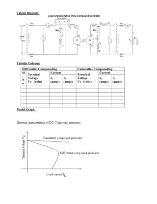
1. Circuit Diagram:
Tabular Column:
Model Graph:
Differential Compounding Cumulative Compounding
Sl
.
N
o
Terminal
Voltage
VT (volts)
Current
Terminal
Voltage
VT (volts)
Current
IL
(amps)
Ia
(amps)
IL
(amps)
Ia
(amps)
2. Experiment Number 7
Load Characteristics of DC Compound Generator
Aim:
To conduct load test on a given DC compound generator and to obtain internal and external
characteristics at rated speed.
Apparatus Required:
Sl No Item Range Quantity
1 Ammeter 1
2 Ammeter 1
3 Voltmeter 0-300V 1
4 Rheostats
5 Rheostats
6 SPST Switch 1
7 Tachometer(Digital) 1-99999 RPM 1
Theory:
In compound generator, since the net field is the sum of the shunt and series fields, depending
upon the connections, addition or subtraction of fields results in cumulative compounding and
differential compounding. The variation of terminal voltage with load current is called external
characteristics. The characteristic which gives the variation of terminal voltage with armature
current is called the internal characteristics.
The compound generator having both shunt and series windings combines the properties of
both the generators. In cumulative compound generator, the windings assist each other so that the
magnetizing forces are added. Here the effect of shunt winding is predominant, while the series
winding is provided to compensate the magnetizing forces of armature reaction and voltage drop
at a definite lag. It is used in application where it is necessary to automatically maintain the
voltage constant when sharp change in loading occurs. In differential compound generator, the
windings are connected such a way that the shunt field flux and series field flux opposes each
other. This causes the terminal voltage to fall at a rapid rate with increase in load current. The
differential compound generator characteristic, there fore, does not have any useful applications.
Procedure:
1. Make the connection as per circuit diagram.
2. Check all meters for zero errors and if there are any deflections correct it.
3. For running as a compound generator, include the series field winding.
4. Keep the motor field rheostat in minimum position and generator field rheostat in
maximum position.
5. Switch on the supply and start the motor using 3-poinr starter by moving the handle slowly
to cut off the resistance.
6. Note down the Ammeter reading.
7. Adjust the field rheostat of the motor to obtain rated speed of the motor.
8. Adjust generator field rheostat to obtain the rated voltage (Eg).
9. Note down the ammeter and voltmeter readings from no load to full load by closing the
switch.
10. On completion of experiment, reduce the load to its initial position and switch off the
supply.
11. For differential compounding, reverse the terminals of the series winding and repeat the
same procedure.
Result: Thus, the load test on a given DC compound generator was conducted and internal
and external characteristics at rated speed for cumulative and differential compounding were
drawn.