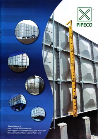
Catalogue pipeco 2012
•
3 recomendaciones•4,791 vistas

Bon nuoc lap ghep dat tieu chuan SS 245, san xuat tai Malaysia, hieu Pipeco

Recomendados
Más contenido relacionado
La actualidad más candente
La actualidad más candente (20)
Similar a Catalogue pipeco 2012
Similar a Catalogue pipeco 2012 (20)
Último
Último (20)
Catalogue pipeco 2012
- 1. X x{ PIPEEO Ii
- 2. Malaysia - Melaka South Africa Time Square Brunei Darussalam Il ;ir- Oman Fra n ce
- 3. INTRODUCTION PIPECO wasformed in 1984 as an engineering hardware company and ventLrres into sectional panel water tank business in 1989.To date, PIPECO has 20 yea rs' experie nce in Production Facilities the business that can provide water storage solution for a variety of applications ranging from I m3 to 5000m3. PIPECO is now one of the largest sectiona tank suppliers in world, supplying both pressed steel and GRP/ FRP sectional water tanks to /4alaysia, Singapore, Vietnam, l,4yanmat Brunei, U.A.E, Qatar, Kuwait, Saudi Arabia, lraq, Oman, Lebanon, Jordan, Algeria, Sudan, France, Begium, Tahiti, Australia, Maldives, Seychelles, South Africa, Romania, Bahrain, Sierra Leona and etc. The production facilities are housed in two factories located in Shah Alam and Pon Klang, Malaysia, with combined 33,OOOm' area and an annua prodLrction capacity of 300,000 GRP / FRP tank panels and 50,000 pressed steel tank panel. This allows PIPECO to fulfi I customer's needs with competitive pricing, prompt delivery and consistent, high quality produ.ts. PIPECO strives to provide the best quality product to the customer To achieve this objective, PIPECO undertakes a production quallity management system that complies to the ISO 9001:2008 standard, and has been accredited since 2003. This ensures that the tank panel and accessories are produced under the most stringent quality audit and meet the required structural and durability performance. By using advanced production facilities and empioyinq a team of highly skilled production staff, PIPECO is able to ensure that the tank panel and tank accessories prodLrced conform to a consistent high quality standard. ln addition, customer services are the highest concern for PIPECO. Therefore, PIPECO is involved in advisinq the c ients through all stages of the tank provision, from the initial design stage, supply and installation stages up to the final commissioning stage. This ensures that the specific needs of the customers are rnet up to the hiqhest possible level. rTi.E f
- 5. GENERAL SPECIFICATIONS Standard i Singapore Standard 55245: I995 Cross reference to British Standard BSJ491 Patt 3.1994 and BS EN 13280:2001 Materials: Resin- lsophthalic unsaturated polyester resin conforming to BS 3532 specification FiberGlass Low alkalifibre glass conforming to Jls R3411 to R3417 or BS 3396, BS 3496 and BS 3749 specifications Te5ting Method: BS 27a2 Manufacturing Process : Sl,4c hot pressed compression moulding Tank Structural Support : : StandardType rHot Dipped Galvanised Steel OptionalType : External Braced type (Metal-Free tank internal for non- partitioned tank only). lnternal : Standard Type:55 304Tie-Rod or Cleat / Angle Stay Optional Type : SS 3 1 6Tie Rod or Cleat / Angle Stay RoofSupport : PVCVertical Poles and GRP roof panel stiffener Sealant: Non toxic PVC foam Bolt, Nuts, washers : Fxternal Standard Hot Dipped Galvanised steel Optional SS 304/A2 or SS 316/44 lnternal Standard SS 304/42 (ln-contact with water) Optional 5S 316/A4 (ln-contact with water) : Hot Dipped Galvanised Steel or unless otherwise specified Ladder: External Standard: Hot Dipped Galvanised Steel lnternal - Standard : PVC Optional : GRP or 3I6 Water Level lndicator: Standard : Reversed Reading Mechanical Ball FloatType with Mouse Opljonal : Direct Reading ClearTubeType Nozzle Panel : Flatpanelswill be providedforanytypeof piping materials
- 6. BASE PANEL TOP PANEL "t 'l 4 E[ FL Trr-- --- - -/---- = Base Panel 1m x 1m BasePanellm x 0.5m Top Panel 1m x 1m Top Panel 1m x 0.5m SIDE PANEL .I Rtl --l Rtf-- = l Ptl ---------..-] ----- FIL-^--il rtll-^=ll Ftlt,-^-ll Side Panel 1m x 1m Side Panel 1m x o-sm Side Panel lm x 1.5m Performance of Panels Tensile Strength (lMN/m':) 103 >70 (min) Bending Strength (MN/m'?) 170 > 100 (min) Elastic Modulus in Bend (l4N/m') 13580 > 6000 (min) class content (Yo) 39 > 25 (min) Barcol Hardness 59 >30 (min). Water Absorption (%) 0.05 1.0 (max)
- 7. NOZZLE / FLAT PANEL MANHOLE F[f rtf ------- :31",-]i-==_L- d lr-- rt .L______ll lt,: {tl =L Lr- -f Nozzle/Flat Panel 1m Y I m Nozzle/Flat Panel lm x 0.5m fu4anhole ]rn x 1m PRE-INSULATED PANEL , l +.+l -tr:r l[ o r::::.:::-::::*u Top Panel 1m x I m Side Panellm x 1m By encapsulating a 25mm - 50mm layer of rigid polyurethane foam, PIPECO pre-insulated panel could maintain the desired water temperature stored inside the tank under extreme temperature condition. PIPECO pre insulated panel could be selected for water storage where there i5 a need to stabilize the temperature against extreme heat or freezing conditions so to prevent dew formation.
- 8. Skid Base Specifications for GRP / FRP sectional water tank *4m x 4m skid base illustration l.0m not provided not provided 1000mm c/c l.5m C-channel 100mm x 50mm Angle 50mm x 50mm 1000mm c/c 2.0m C-channel 100mm x 50mm Angle 50mm x 50mm 1000mm c/c 2.5m C-channel 125mm x 65mm Angle 65mm x 65mm 'l000mmc/c 3.0m C-channel 125mm x 65mm Angle 65mm x 65mm 1000mm c/c 3.5m C-channel 150mm x 75mm Angle 75mm x 75mm 1000mm c/c 4.0m C-channel i 50mm x 75mm Angle 75mm x 75mm 1000mm c/c *PIPECO reserv€s the right to provide alternate skid base designs PIPECO recommends an ideal concrete plinth size of 300mm (W) x 600mm (H), with maximum variance in height of not more than 2mm
- 9. Overview of internal structural support for GRP/FRP sectional water tank PIPECO GRP/FRP sectional water tank is constructed with bottom, side and top panels, completes with external and internal structural reinforcement and necessary tank accessories to facilitate water storage AirVent Manhole Pole Support Eternat Laddet Top Panel y--- Corner Angle WaterLevel lndicator RoofSupport Side Panel Eody Angle Side Panel Support lnternal Ladder Sray Plate Bottom Panel Flat Bar Or.in / PitP"n"l--& I 5nr r 4!n r 4nriH GRP FRP !e.t o r: witer tnfk illll!t .tr.rl Top Panel Body Angle Pole Access Manhole Side Panel Corner Angle Pole Support Air Vent Bottorn Panel Side PanelSupport Tie Rod Water Level lndicator Drain/Pit Panel Flat Bar Roof Support lnternal Ladder Stay Plate ln Corner Bracket External Ladder
- 10. Overview of external structural support for GRP/FRP sectional water tank Air Vent Pole Sup port ln corner Bracket ( HDG Rod Top Panel - --il.. Tube Level lndicator c-channel Body Angle External Bracing Support side I Beam Support Bracket Flat Bar Bottom Drain / Pit Panel irlr lnrrInlHlrrtr,llrii ,, ,,r r,r 'li L.,r rl',' Pole Support
- 11. Top Panel Pole External Ladder Side Panel Pole Support Bottom Panel Roof Support Drain / Pit Panel Bottom Pole Support ln Corner Bracket Manhole Flat Bar Access Manhole Body Angle lnternal Ladder Roof Support Side Panel Support External Ladder C Channel VerticallBeam Tube Levellndicator HDG Rod Side I Beam Support lnternal Ladder Bracket External Bracing Support Side Panel Support Side I Beam Project for external braced water tank ,.... Side Panel $i{{ Pole Bottom Panel
- 13. GENERAL SPECIFICATIONS Standard: PIPECO pressed steel sectional water tank constructed with hydraulically pressed flanged panels, conform to Bs I564: 1975 Materials: The steel used in the manufacture ofthe tank plates, stays and cleats conform to the requirements of BS4360:1972 grade 43A or l5O equivalent Flanges of Plates: The tank plates are pressed with a combined doub e flange at an a ngle of45 degree and 90 degree to the face ofthe piate on four sides 5tay5 and Cleat5: The stays and cleats are made of steel angle bar and steel plate Bolts, Nuts and Wa5he15: Hot Dipped Galvanised steel bolt5, nuts and washers for internal and externai Jointing Materia15 i Non toxic PVC foam to be used foralljointing between tank panelflange Tank Cover: Paneltype or pitched type stee I cover s u pported bytrusses 600 x 600 square manhole and 100mm air-vent supplied as standard foreach compartment Water Level lndicator: Mechanical Ball FloatType Ladder: Aluminiurn or HDG Steel ladderfor internal and external ac.ess Finish: (a) Hot Dip Galvanised conform to BS 729 or l5o equivalent (b) Black Bituminous Coated Standard Thickness for 1,22m x 1.22m Tank Panel 4th slde panel5 5mm 3rd side panels 5mm 5mm 2nd side panels 5mm 5mm 5mm l st side panels 5mm 5mm 5mm 6mm Bottom panels 5mm 5mm 5mm 6mm Standard Thickness for 1m x t mTank Panel 5th side panels 5mm 4th side panels 5mm 5mm 3rd side panels 5mm 5mm 5mm 2nd side panels 5mm 5mm 5mm 1st side panels 5mm 5mm 5mm Bottom panels 5mm 5mm 5mm
- 14. l. S<ope (c) Limiting .onditions, ifany, as to spaceand This Bitish Standad specifes requirement for pressed accessibilityfor erection, and whetherth€ tankwi be sleel sectional rectangulartanks, working undera €rected in a bujding orexposed totheweather, andthe pressure not greater rhan the static head corresponding heiqht aboveground eve it is to be installed. to the depth ofthe tanks, built up of pressed steel plares (d) Nature and d€nsity ofliqLridforwhich thetank is 1220mm square used to contain cold wat€r, hot water, 'eqLi..d.l''o ro.rve pa n.u d robegrver.ltwarp..rdre potable liquids,.ertain oils and chemicals.Tanks may b€ whether hard or soft.The rate ofil ing and emptying the constructed as follows: tank, head fluctuations and cycles perday. (€) and minimum temp€rarures and {a) with external flanges; (b) with internal bottom fla nges, enernalsideand ^4axinrum approxinrate rate ofiuctuation and position of heating Two types are specified: (f) Any special requirements as tojointing materialand Iyp€ i.With a combined doubleflangeatan angleof as to internaland externalcoating or lagqing. 45" and 90' to the plane of the plate on all four sides NOIE: n the ab,en.e ofany.pecialrequnemens ohecoat ofa as illustGted in figure I The plates oftype 1 tanks suitab e primlhs painrwillbe applied 1o prore.tthetahk durinq are hot pressed complete. de ivery and erstion. A minimh of two further .oaB shou d be Iype 2. With a single fange at an angle of90"to rhe plane ofthe p ate on each of two, there orfour sidet dependinq on its position in the tank.Type 2 tanks (g) Particulals ofconnections and drillinq required and are cold pressedas illustrated in figure 2, with the precise location on tankwith dinrensioned sk€tches, flange corners we ded. hdvi,rg reqard ro pos5rble tutLro r4quiremenrs This standard does not provide fortanks subject to eadh (h)Whether externalaccess ladder, are required and, if orotherexterna pressureotherthanwind pressure. so, parti.u a15to be given. (i) Details ofany existinq or propoled supponing NoTE.Foranillustrationof atypicaltankextema ilansesseenq!re structure and height of bottom oftank above ground 3. For approximate weights and fu nomina capacities { without level so that the necessdry scaffolding arrangements fteeboard)ofopen top ta.ks seetab es I toa, .an be made to complywith statutorysafety rcgulations. (j) Whether tla nsverse supporting bearel, are r€quired Tanks can also be assembled with all flanges internal with the addition of other components, but because of and, ifso, particulars as to span and end suppon to be given. the diffrculty ofassembling and maintaining rht type of (k)Whetherthe tank is to be used for otherthaf a tank they are not preferred- stationary application. All tanks can be supplied with open or closed top. (l) Whether nspection will be made by the lnformation on erection and supports is also included. representtive ofthe purchaser afthe works ofthe 2. References (m)Wheth€r erection is to be carried out by the The titles ofthe British Standards refeffed to in this stan- manufacturer at site; ifso, information as to site dard are listed on the inside backcover. conditions and acce5sibiityro beqiven bythe 3. lnformation to be supplied with the enquiry and order 4.Working tempelatures The following information, as appropriate,should be Forthe purpose ofthis standatu cold iquids are defined as supplied by the purchaser with his enquiry or ord-"r. those having a temperature not exceeding 38.C and hot (a) Iype of tank required (clause t), type of cover (if liquids are defi ned as those having a temperature ex.eeding any), numb€rand posilion and typeof 38'C but lessthan I00'C. mdnholer<r. numher of divi.roni it rpquired ln the case oftanks to hold hot iquids, care shallberaken in (b) Capacity required in lit€rs ordimensions in use to avoid excessive vibration or turbulence.Tanks for r.illimeters in multiples of 1220 mmand whether temperatures higher than 100'c should be the subject of cny p'ovrs on i o be -dde fo. fulur. .xt"niion mutual arrangement between the p!rchaser and rhe and ifany level indicator! are rcquir€d.
- 15. 5. Materials 9. Flanges of plate 5.1The steel used in the manufacture of the plates, P.te shal be pressed with a combined double flange at an stays. cleats and pads for connections shall conform to anqle of 45' and 90" to the face ofthe plate on allfour sides the requirements of 85 4360: 1972 grade 43A or 85 (type 1 figure 1) or a single flange at an angle of 90" to the 12149: Part 1: 1972 material HR 14. p ate on each of two, three orfoursides (type 2 igure 2),the 5.2 Bolts, studs, nuts and washe6 shall be made from flanqes ho ed according tothe respective position ofthe piate steel complying with the requirements of 8S 4190. n rhe tankand freefrom irregularities. BoJc a nd n uts sha ll be hexagonal, b lack fin ish, screwed The w dth ol the flanqe, shall be not less than 45 mm, the lso metric complying with the requircments of Bs holes for the bo ts hav nq a .learance of 1.5 rnm in diameter, 4190, where applicable.Wash€rs shall .omply with the the bo ts h.v n9 a min mum diameter of l4 mm (Ml4). The requirements of BS 4320: 1968 from'F: 5pacing of bo ts holes sha not exceed 76.2 mm pitch. 6. Dimensions ol unit plates 10. Jointinq material The nominal size of unit plates shall be 1200 mm Thejointinq to be !sed for tank rha I be suitable for the square.the actua I overa ll d imen sions depending upon conditions and shal be a matter for mutual agreement the particular manufacturer of the plates. Th€ size of between ihe purcha5er.nd manufacturer. Anyjointing lsed tanks shall be spe.ified as multiples of the nominal sha be insolub e in the I qu d to be stored and, where necessary, sha lbe non'tox c. 7.Thi<kness of unit plates 11. Bolts, studs, nuts and washers Zl Forcold liquids with a d€nsity not exceeding ] 0 the Bohr, studs nut, and washeB shall be in accordance with th€ nominal thickness of the plat€ from which the unit requ remenr specified in s.2. Each flange bo ts sha I be ftted plates are pressed shall be not less than: with one fla1 washer under the nut and the d arileter of the bo ts shal be not ess than '14 mm (Ml4). Tank 1220mm in depthl bottom, sidesand ends. 5 12. Staying Tank 2440 mm in depth: i2. / Th€ sldes and ends ofal tanks shallbesupported by stays bottom, sidesand ends. s at thejunction of two or more plates the stays sha lmadeftom Tanl(s 3660 mm in depth: mild steelrolled sections calculated in ac.ordancewith clause bottom. sides and ends. s 7. Stays shall be attached to the plates by boltinq to cleats of Tanks 4880 mm in depth: equal strength bolted to tank pates; stay attachments to -bottom, and 6rst t er of sid€s cleats and c eats to tank plates shall be calculated taking into and ends 6 account eccentricity of loading.The ends of the stays shall be -!econd, third and top ti€rs of attached to the c eats ortank plate, by bolts. sides and ends. 5 12.2 5tays sha I connect sider to bottom, ends to bottom andi or hor zonta ly sides and sides to ends generaly in Z2 For hot liquids with a d€nsity not exceeding 1.0 no accord.ncewthfigureS. plate shall less than 6 mm in thickness. Z3 For cold or hot liquids with a density greater than 13. Connections ] 0 the platethicknesses shall be a matterfor mutual iJ. / Pads for connections, tapped bosses, screwed flanges or afiangement between the purchaserand the sockets, as may be requ red bythe purchaser, shallbe welded to the nside or outside or bohed tothetank plate. Pads shall be dr I ed, and/ ortapped as ne.elsary to suit flanges 8. Permissible stresses .omp y nq wth the requirements of 854504, or such other The calculated stress in any stay and attachment and standard as specified by the purchaser Single pads shall be bolts shall comply with th€ requirements of Bs 449, provided for connection on one side ofth€ plate and double dnd any allowanca thar "1ay be requled tor (or.o5 or p.d5 for connection on both sides ofthe plate.Tapped socks shallbeadded to the calculdted thickness. sha compywiththe requirenrents specifred in BS 1387. Typicaltypes ofwelded connections are shown in fgures 3 to
- 16. l4.Weldlng of <onn€ctions '18. Marking Welds for connections shall be made by rhe metal All tanks complying with the requirements of this are process complying with the requirements of BS standard shall be legibly marked as follows. 1856 and by means of covered electrodes comply- (a) Manufacturer! name, mark or initial_ inq with the requirements of85639 r1972 sections l (h)The number ofthis British Standard, i.e. BS 1564. and 2:grade l. 19. Minimum access l5.5upports Where tanks with externalflanges are to be erected All tanks shall effectively supported in accordance in a confined space it is essentialthata clearrnce of with the manufacturer's recom m endations a nd not less than 500 mm shallbe provided allround tolerances. Supports shall he provided rontinuously rhe out,de dno Jnoer,ledlh Lo lactl,tdre precrion. under each bottom flang€ in one direction at 1220 Foraccess to the top of a closed rankthe cleardnce rnm centers,Tanks with internalbo(om flanges can atthe top shall be not lessthan 750 mm. also rest direcdy on a flats level base A NoTE,A owan.esholldbemadeforinspectonand sand/bitumen bed 50 mm thick is recommended in maint€nanc€ in. uding valv€s or oiher extehal ttttings. that case. Where steel joists a re used they sha ll be designed to carry the imposed load with a 20.lnspection maximum deflection of one five,hundredth of the 20.I Works inspection.The purchaser or his span, Attention js drawn to the extra reaction on the representative shallhave access to rheworks of th€ supports under the side, end and division plates manufacturer at all reasonable tim€s and shall be at when thestays ofsides, ends and divisions are ibertyto inspectand ro reject any materiajwhich inc ined to th€ bottom ofthe tank. dop, rol comply with rhe requ Fments ot thi nandard. Such inspection shall include verification 16. Closed top tanks that the unit plates will mate rogether and 76.7 Coverframinq members shall be designed to dsen ble.Wherepart,a or (on pletea+on"ory;s withstand sup€rimposed Joadings compiyinq with required at the works ofthe manufacturer, rhis shall the requirements of BS 449- be the subject ofspecific arrangement berween the 16.2 Covers may be flat indoor use and should h€ purchaser and the manufactureratthe time of pitched or cambered for outdoor use, andjointed to ensurethattheyare dust and weather prool 16.3 Covers may be constructed of steel plates or 20.2 Site inspection.The purchaser or his other con structio na I cladding materia ls. representarive shall ensur€ that 5upports are within 16.4 ln all cases clos€d top tank shall be provided the to erances required by the manufacturer before with a manhole of not less than 460 mm diameter the commen.ement of erection. clear opening to give access to the inside ofthe lank and with a suitable vent, filtered ifnecessary to the 21. Erection manufacturerl requirements to avoid pressure Erection shall be cdrried out in a.cordance with th€ changes within the tank. manufacturer's instructions, 17. A<<ess Ladders 22.Testing Tanks over 1220mm deep shall be provided with a Testing sha I be frlling the tank with water on site steel internal access ladder. ln covered tanks the and shall be the subject of specific arranqement ladder shall b€ adjacent to the manhole. between the purchaser and the manufactureratthe NOTE. E{ernal laddeE may h. provid€d requned, artention G time ofthe enquiry and order.Waterfor testing shall be supplied by rhe purchaser
- 17. GENERAL SPECIFICATIONS Standard: PIPECO pressed stainless steel sectional water tank constructed with hydraulically pressed flanged panels r Material5: The tank panel, stays and cleats are made from L Stainless Steel Grade 304 / 316 Flanges of Plates : The tank plates are pressed with a combined double flange at an angle of 45 degree and 90 degree to the face ofthe plate on four sides Bolts, Nuts and Washers: Stainless SteelGrade304/316 bolts, nuts and washer Jointing Materials: Non toxic PVC foam to be used for alljointing between tank panel flange TankCover: Panel type tank cover supported by trusses and poles 600 x 600 square manhole and supplied as standard for each compartment Water Level lndicator: Mechanical Ball FloatType Nozzles for Connection : Short pipe with flange or socket for all pipe connections Ladder: lnternal ladder shall bemadeofStainlessStee 304/3l6andaluminiumforexternal ladder Standard Thickness for 1.22m x 1.22m Tank Panel 4th side panels 2.5mm 3rd side panels 2.5mm 2.5mm 2nd side panels 2.5mm 2.5mm 3.0mm 1st side panels 2.5mm 2.5mm 3.0mm 4.0mrn Bottom panels 2-5mm 2.5mm 3.0mm 4.0mm Standard Thickness for 1m x I m Tank Panel 4th side panels 2.5mm 3rd side panels 2.5mm 2.5mm 2nd side panels 2.5mm 2.5mm 3.0mm 1st side panels 2.5mm 3.0mm 3.0mm Bottom panels 2.5mm 3.0mm 3.0mm
- 18. WRAS ;i @ sP4i, @ 0 I W 2h:: tt *-{*'. '' z
- 19. Abu Dhabi Broome Hospital, Au stralia Malaysia - Cyber Jaya West Africa U.A.E