Ghosted Illustration from 3D CAD
•
7 recomendaciones•3,582 vistas

Using SIEMENS PLM's NX Non-Photo-Realistic render application (Lightwork Design Ltd. - Artistic Image - render engine) to generate source images for technical illustration. Step by Step guide

Recomendados
Recomendados
Más contenido relacionado
La actualidad más candente
La actualidad más candente (12)
Destacado
Destacado (20)
Similar a Ghosted Illustration from 3D CAD
Similar a Ghosted Illustration from 3D CAD (20)
Último
Último (20)
Ghosted Illustration from 3D CAD
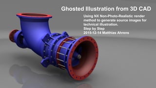
- 1. Using NX Non-Photo-Realistic render method to generate source images for technical illustration. Step by Step 2015-12-14 Matthias Ahrens Ghosted Illustration from 3D CAD
- 2. 2 2015-12-14 / Ghosted Illustration from 3D CAD / M. Ahrens • Present inner parts in context of the outer product design • Using SIEMENS PLM NX 3D CAD model as source for a technical illustration • Using NX embedded Lightwork Design Ltd. render engine • Reduce utilization of external tools to a minimum to react faster on design changes The intention
- 3. 3 2015-12-14 / Ghosted Illustration from 3D CAD / M. Ahrens • Identify components of interest • Define a accurate camera for reuse • Define (Section) views for the different levels of depth • Set background • Set lights • Set floor • Define Visualization Scene for synchronizing multiple Model Views • Set resolution, size and quality for rendering process • Render multiple passes of artistic images • Compose final image in graphic tools (e.g. GIMP) The process
- 4. 4 2015-12-14 / Ghosted Illustration from 3D CAD / M. Ahrens • Analyze the CAD model and identify the components resp. areas of interest, which should be presented in context and focused via the illustration. • The “View Section” command can be used to identify inner areas. Identify components of interest
- 5. 5 2015-12-14 / Ghosted Illustration from 3D CAD / M. Ahrens • Define a Camera and take care for “Perspective” and “Lens” settings. • Recommendation: Use a “Zoom to” value of 50mm Define a accurate camera for reuse
- 6. 6 2015-12-14 / Ghosted Illustration from 3D CAD / M. Ahrens • Based on the areas of interest define multiple “Model Views”. • Create “Cutouts” to provide direct views from camera position to details. • Recommendation: Use the following steps to define such views. Define (Section) views for the different levels of depth L00 L01 L02
- 7. 7 2015-12-14 / Ghosted Illustration from 3D CAD / M. Ahrens • Create a set of closed curves for the cutout section on a new datum plane. • Remember camera’s point of view to get best section lines (red & magenta) Define (Section) views for the different levels of depth L00 L01 L02
- 8. 8 2015-12-14 / Ghosted Illustration from 3D CAD / M. Ahrens • Use the “PMI” function “Section View…” to generate related cutouts. • Attention: “Lightweight Section View…” cannot be used for rendering! Define (Section) views for the different levels of depth
- 9. 9 2015-12-14 / Ghosted Illustration from 3D CAD / M. Ahrens • If components are not tackled by the “Section View…” command, the Assembly – Context Control command “Hide Components in View…” can be used to hide components in the current work view only. Define (Section) views for the different levels of depth
- 10. 10 2015-12-14 / Ghosted Illustration from 3D CAD / M. Ahrens • Switch to Advanced Studio mode and enter Scene Editor. • Take care that the lights producing shadows to provide information of depth. • HDRI resp. Image Based Lighting is not required here. Enter visualization environment
- 11. 11 2015-12-14 / Ghosted Illustration from 3D CAD / M. Ahrens • Often a white, plain background is preferred for technical illustrations. Set background
- 12. 12 2015-12-14 / Ghosted Illustration from 3D CAD / M. Ahrens • Switch to Advanced Lights setting and generate simple lighting schema. • Take care for intensity and shadow generation! • Verify lights definition in “Scene Editor” to ensure accurate setup! Set lights
- 13. 13 2015-12-14 / Ghosted Illustration from 3D CAD / M. Ahrens • Ensure that IBL (Image-Based Lighting) is not used! • Even if IBL is producing sometimes more realistic results for High Quality Images the shadow control can become worst for Artistic Image renderings! Set lights Artistic Image: High Quality Image:
- 14. 14 2015-12-14 / Ghosted Illustration from 3D CAD / M. Ahrens • Similar to the standard Three-Point Lighting for photographs the light setup for artistic images is important to compose accurate shadow results. • A dedicated RIM resp. Back Light is not required here! Set lights By an accurate intensity setting for the Key Light and the Fill Light a shadow result at two levels can be achieved!
- 15. 15 2015-12-14 / Ghosted Illustration from 3D CAD / M. Ahrens • Activate the floor as Shadow Catcher to nail the product to the ground. Set floor
- 16. 16 2015-12-14 / Ghosted Illustration from 3D CAD / M. Ahrens • The most of the scene settings will be defined and stored in context of the model view! • Therefore it is recommended to generate a dedicated “Visualization Scene” for this product shot in a new “Palette”! Define Visualization Scene for synchronizing multiple Model Views
- 17. 17 2015-12-14 / Ghosted Illustration from 3D CAD / M. Ahrens • Apply the new, custom “Visualization Scene” to all custom model views, which will be used for the ghosted illustration. • You have to update and reapply these “Visualization Scene” whenever an adjustment of the lighting is required. Define Visualization Scene for synchronizing multiple Model Views
- 18. 18 2015-12-14 / Ghosted Illustration from 3D CAD / M. Ahrens • Use the High Quality Image dialog to adjust preferences for the Lightwork Design Ltd. software render engine. • Settings like “resolution” will be honored by the Artistic Image algorithms too. Set resolution, size and quality for rendering process Example of required image sizes and resolutions: Width: 297mm 7016px 3508px Height: 210mm 4961px 2480px Resolution: 600dpi 300dpi • Be carefully with the size of the image! • Larger bit planes can increase render processing time dramatically!
- 19. 19 2015-12-14 / Ghosted Illustration from 3D CAD / M. Ahrens • Run a few tests at lower resolution with the “Artistic Image” - “Cartoon” or “Color Wash” and “Lines and Shadows” to check shadows and colors. • If required, adjust colors of bodies to realize better contrast. Set resolution, size and quality for rendering process
- 20. 20 2015-12-14 / Ghosted Illustration from 3D CAD / M. Ahrens • Render “Color Wash” and two times “Lines and Shadows” at final resolution. • Take care that is activated for “Shadow” cycles only. • Flip black/white for “Lines and Shadows” to separate them into two passes. • After each pass use the “High Quality Image” save dialog without closing the “Artistic Image” dialog to store the images. • In the “Save Image” dialog enter the file name extension “.jpg” to force JPEG. Render multiple passes of artistic images
- 21. 21 2015-12-14 / Ghosted Illustration from 3D CAD / M. Ahrens • Based on detailing level process “Artistic Image” for each slice of illustration. • Hide unwanted bodies and components per slice. • Take care for camera position (reapply camera upfront each rendering cycle!) • Take care that at least the zero layer shadow image contains ground shadows by activating the stage floor. Render multiple passes of artistic images L00 L01 L02
- 22. 22 2015-12-14 / Ghosted Illustration from 3D CAD / M. Ahrens • Load all images as “layers” into image manipulation tool (e.g. drag and drop). • Sort them in a logical order with the nearest layer on top. Compose final image in graphic tools (e.g. GIMP)
- 23. 23 2015-12-14 / Ghosted Illustration from 3D CAD / M. Ahrens • Make the “white” the transparent area in the “Lines” and “Shadow” layers. Compose final image in graphic tools (e.g. GIMP)
- 24. 24 2015-12-14 / Ghosted Illustration from 3D CAD / M. Ahrens • Ad a “Layer Mask” to the “Color Wash” layers and paint the areas, which should become transparent with the “Airbrush” tool. Compose final image in graphic tools (e.g. GIMP)
- 25. 25 2015-12-14 / Ghosted Illustration from 3D CAD / M. Ahrens • Use the various Hide/Show options and the Black/White colors to adjust level of transparency and review result across multiple layers. Compose final image in graphic tools (e.g. GIMP)
- 26. 26 2015-12-14 / Ghosted Illustration from 3D CAD / M. Ahrens • Use the “Opacity” slider to adjust “Shadow” intensity. Compose final image in graphic tools (e.g. GIMP)
- 27. 27 2015-12-14 / Ghosted Illustration from 3D CAD / M. Ahrens • Add “Layer Mask” to “Lines” layers too and vary area of transparency to let the lines become a little bit longer or shorter than the shaded areas. Compose final image in graphic tools (e.g. GIMP)
- 28. 28 2015-12-14 / Ghosted Illustration from 3D CAD / M. Ahrens • Use “Gaussian Blur” effect with larger values on “Layer Masks” to smoothen transition between opacity and transparency areas. Compose final image in graphic tools (e.g. GIMP)
- 29. 29 2015-12-14 / Ghosted Illustration from 3D CAD / M. Ahrens • Use “Gaussian Blur” effect with smaller values on outer “Color Wash” and “Shadow” layers to achieve a kind of “Out of focus” effect. Compose final image in graphic tools (e.g. GIMP)
- 30. 30 2015-12-14 / Ghosted Illustration from 3D CAD / M. Ahrens • Export the image into a common format (e.g. jpg) and keep the image in GIMP file (.xcf) format for later adjustments or fine tunings. • Keep in mind… the camera position and color settings are still stored in the NX CAD file. • In cases of iterations a redo of the rendering and the composing is required. • But maybe only a few “slices” have to be revised while the outer shell is still valid? Compose final image in graphic tools (e.g. GIMP)
- 31. 31 2015-12-14 / Ghosted Illustration from 3D CAD / M. Ahrens The result
- 32. 32 2015-12-14 / Ghosted Illustration from 3D CAD / M. Ahrens • The 3D model “Axial Pump”, used for this illustration, was gathered from GRABCAD and was designed by Kostiantyn Abramov The 3D model source