Bd Weather
•Descargar como PPTX, PDF•
1 recomendación•912 vistas

Thermal imaging can be used for energy auditing and weatherization to locate air leaks, moisture issues, and other problems. An energy audit uses tools like a thermal imager, blower door, and other equipment to evaluate energy usage and pinpoint areas of energy loss. Weatherization involves sealing leaks and improving insulation. Thermal imaging makes inspections easier and more effective by allowing users to quickly scan areas and see problems like missing insulation or air leaks without disturbing structures. It provides visual documentation of issues found before and after repairs. Focusing the thermal imager properly and understanding parameters like level, span, and emissivity are important for capturing accurate temperature data.

Recomendados
Recomendados
Más contenido relacionado
La actualidad más candente
La actualidad más candente (20)
Destacado
Destacado (17)
Similar a Bd Weather
Similar a Bd Weather (20)
Bd Weather
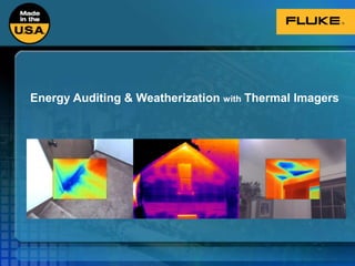
- 1. Energy Auditing & Weatherization with Thermal Imagers
- 2. Agenda Energy Auditing, Weatherization & Energy Use Where & How Thermal Imaging Fits In IR-Fusion® technology Air Leaks & Insulation Moisture Electrical Roofs Thermography physics and heat transfer How a thermal imager works Resolving detail and parameters of a good image Fluke Thermal Imagers SmartView® Software
- 3. How We Use Energy in Our Homes Source: DOE - http://www1.eere.energy.gov/consumer/tips/home_energy.html Date Accessed: 4/20/2009
- 4. Energy Auditing & Weatherization Energy Audit Evaluate energy use and pinpoint areas of energy loss Thermal imager, blower door, smoke pen, air tester, energy monitor Weatherization Includes a wide variety of energy efficiency measures that encompass the building envelope, its heating and cooling systems, its electrical system, and electricity consuming appliances Corrective action based on findings Follow up scan with infrared to verify repairs Source: DOE - http://apps1.eere.energy.gov/weatherization/what_is.cfm Date Accessed: 4/20/2009
- 5. According to ENERGY STAR®: “…sealing and insulating the "envelope" or "shell" of your home — its outer walls, ceiling, windows, doors, and floors — is often the most cost effective way to improve energy efficiency and comfort.” Source - http://www.energystar.gov/index.cfm?c=home_sealing.hm_improvement_sealing Date Accessed: 4/20/2009
- 6. Common Air Leak Sources Source: DOE - http://www1.eere.energy.gov/consumer/tips/air_leaks.html Date Accessed: 4/20/2009
- 7. Why Thermal Imaging? Easier & more effective inspection Customers request it More competitive Build business & make more money
- 8. What is Thermography? Infrared radiation is emitted by all objects The amount of radiation increases with temperature It is the science of “seeing” temperature by measuring the radiation emitted from an object and converting this data to a corresponding digital, or visual image called a thermogram We are only measuring the surface temperature!
- 9. What Does an IR Camera Do? Displays the thermal patterns on a given surface by converting temperature data to a digital image Can also provide advanced temperature measurements Provides visual verification and documentation of moisture problems, before and after Most importantly – reduces liability, improves efficiency, adds revenue stream
- 10. Why use Thermal Imaging? Hot or cold areas, or thermal anomalies, often are a strong indicator of potential problems Thermal Imaging works well to inspect: Building Inspections Residential - Home Inspectors Commercial – Property Managers Energy Audits/Weatherization Termite/Pest Control Water damage Commercial Low Slope Roofing Construction Defect Management or Building Forensic Firms Plumbing/Radiant Heat
- 11. Thermography Benefits Measurements are: Non-contact Obtained without disturbing structure Very sensitive to problem characteristics Detect problem before significant damage Can scan large areas quickly Identifies specific location
- 12. Why Thermal Imaging? “The time savings alone made my investment in thermal imaging well worth it. Infrared allows me to quickly and easily locate air leaks and missing insulation without having to drill and probe with a manometer.” - Andy Imig Owner, Arrowhead Energy and Comfort Solutions – Esko, MN Instructor, Dunwoody Institute & Fond du Lac Tribal and Community College
- 13. What do we look for? Thermography can identify surface temperature variations that relate to problems with poor construction, missing or inadequate insulation, broken window seals, moisture intrusion and air Air leakage Air Quality Energy Consumption Safety Concerns Occupant comfort Moisture intrusion Health (mold) Construction Problems Maintenance cost Safety Concerns Electrical and Mechanical Systems
- 14. Where do we look? Roof Systems Indoor Walls Floors Ceilings Exterior Thermal bridging Window systems Construction HVAC/R System component operation Duct system Electrical and Mechanical Systems Connections Breakers Fuses
- 15. Air Leaks Become Visible! Fast location of air leaks and missing insulation Non-destructive Easily document & report findings to property owner
- 16. Three Modes of Heat Transfer Radiation is the transmission of electromagnetic rays through space Each material that has a temperature above absolute zero (-460°F) emits infrared radiation, Conduction is direct heat flow through matter Fun fact: Notice how metal feels cold? It is not – that is only the metal taking energy away from your hand and we perceive this as “cold”! Convection is the transport of heat within a gas or liquid Cold air drops so A/C vents are high Warm air rises so heating vents are on floor
- 17. Conduction & Convection Example Outside heat conducted through siding Convected inside empty wall cavity Conducted through inside wall board Convected into air conditioned room
- 18. Air Leaks Image Courtesy of Structure Tech Home Inspections Common causes: Door & window gaps Exterior wall electrical outlets Recessed lights Attic penetrations Ducts / Vents
- 19. Fluke IR-Fusion® Combines visual light and infrared together Easy reference of problem location More effective reporting
- 20. IR-Fusion Viewing Modes Traditional Full IR Color Alarm PIP Full IR Full Visual PIP Blended Blended IR / Visual *Not all viewing modes available on-board all models, all available in software
- 21. Air Leaks Locate exact leak point
- 22. Air Leaks The passage of air through the building envelope, wall, window, joint, etc. Improper air movement significantly reduces the integrity and performance of the envelope and is therefore a major contributor to energy consumption in a building as well as poor air quality
- 23. Air Leaks Poor construction Leaks and penetrations around envelop: Chimneys Plumbing vents HVAC lines Utility lines Leaks around window and doors Poorly installed siding and wraps Damaged and misfit heat ducts
- 24. Construction Defects Find common construction issues such as missing insulation, improper framing, concrete and masonry problems, etc. These images are from a stucco home which had small outside leaks
- 26. Conductive Losses Conductive Losses Missing, compressed or improperly installed insulation Shrinkage or settling of various insulating materials Excessive thermal bridging in joints between walls and tops or bottom plates Moisture damage to insulation and building materials
- 27. Conductive Losses cont. Conductive Losses Heat loss through multi-plane windows with a broken or improperly fitted seal Leaks in water pipes Damaged heat ducts Location of; or leaking in buried steam lines, water line or underground sprinklers
- 28. Energy Efficiency Efficiency reduction causes Hot or cold air infiltration Improper air flow (HVAC) Insulation Voids Thermography can identify surface temperature variations that relate to problems Poor construction, missing or inadequate insulation, broken window seals, moisture intrusion and air leakage Here are images showing lack of proper insulation
- 29. Thermal Bypass ENERGY STAR® Thermal Bypass Checklist Common Areas of Concern: Air and thermal barrier contact Showers & tubs on exterior walls Floors above garages Knee walls Attic access Cantilevered floors Soffits Image Courtesy of Energy Services Group Image Courtesy of Energy Services Group
- 31. Wet insulation does not perform
- 33. MoldMOISTURE
- 34. Moisture Water entering building structure through: Leaks in building envelop Failed and poorly installed plumbing Condensation caused by: Improper construction Poor building management Air leakage All of which can cause health, comfort, safety and financial issues
- 35. Moisture Thermography helped plumbers find water leak in church heating system
- 36. HVAC - Air Conditioner Unit Abnormal Appearance The discharge line is not as hot and appears not as white and the suction line is only slightly cooler. Indicates A/C unit in need of charge or upon HVAC inspection after charge possible compressor blow by. Normal Appearance Suction line (Black = Cold) and discharge line (White = Very hot) on an exterior A/C unit.
- 37. A/C Condenser in Ceiling condenser unit in ceiling above bathtub full of water top of ceiling above bathtub shower wall Condensation drain line in A/c condenser clogged causing water to drip from pan.
- 38. Compressor for in Store Freezing Units Problems here! Caused this problem
- 39. Bridge Deck / In-Floor Heating DOT in Oklahoma Floor preparation for Mud jacking
- 40. Electrical Inspections Easily find electrical problems at the panel or on mechanical equipment
- 41. Electrical Measurements Confirmation of Thermal images Current startup current Running current Loading of Circuits Proper Operating Conditions GFI tester Outlet tester AC Current/Voltage measurements DC Current measurement for Solar system
- 42. Steam Traps Determine valve on/off and leakage
- 43. Roof inspection Wet spots under roof membrane
- 44. Roof inspection Patterns vary with: Roof type Insulation type Deck Conditions Non-absorbent insulation types are more difficult to inspect
- 45. It’s not just about energy loss! Excessive leakage can also cause condensation to form within and on walls which can create many problems: Permanently damage insulation Seriously degrade materials Rot wood Corrode metals Stain brick, concrete or surfaces Extreme cases will cause concrete to spall, bricks to separate, mortar to crumble and sections of wall to fall Corrode structural steal, re-bar and metal hangers and bolts
- 46. What You Need to Know How buildings work & how they are built Heat transfer basics Thermal imager operation Many organizations developing standards RESNET & BPI Local training & certification requirements ASNT SNT-TC-1A
- 47. Be aware: convection (wind) can effect temperature 117F 95F 81F 85F 76F 72F No wind T = 36F T = 13F Photo courtesy of Snell Infrared
- 48. Wind can significantly reduce temperature of hot spot Rule of thumb 10 mph can reduce T by up to 1/2 15 mph can reduce T by up to 2/3 Roof moisture inspection is very difficult in wind Wind Effects
- 49. Conservation of Energy IR cameras detects infrared radiation from the target: Radiation can be transmitted through a surface Our IR camera lens, for example Radiation can be reflected off a surface (background radiation) Similar to your reflection in a mirror Radiation can be absorbed and re-emitted This is what tells us the surface temperature Absorbed & re-emitted Transmitted Reflected Reflected + Absorbed + Transmitted = 1 OR Reflected + Emitted + Transmitted = 1 OR Reflected+ Emitted = 1 This is a key relationship
- 50. Surfaces emit radiation differently, this is called emissivity Pronunciation: "Em`is*siv"i*ty ” Ability for absorbed heat energy to radiate (leave) an object as compared to a device called a black body A true black body radiates 100% of its absorbed energy (nothing is reflected or transmitted) so the ε = 1 Materials that are not black bodies only radiate a fraction of the radiation so the ε is <1 and we have to account for reflected energy We have to “tell” our camera how much radiation is being “emitted” relative to “100%” Putting it all together
- 51. Summary R+E=1 Emitters don’t make good reflectors Reflectors don’t make good emitters Difficult to make accurate measurements on highly reflective surfaces If emissivity is below 0.6 measurement is unreliable
- 52. Simple guidelines All objects of organic origin have emissivity of approx. 0.95 Soil, lime, stone, paper, textile Non-metallic paint, plastic, rubber Oil, grease, dust Apply tape or paint to increase emissivity Whenever possible, increase emissivity!
- 53. Emissivity of Target Surfaces
- 54. Successful IR Audit Air Leaks – ASTM E-1186 ΔT of 3°F for Air Leak Inspection Insulation – ASTM C-1060 ΔT of 18°F for Insulation Inspection Solar Loading & Wind can mask problems Focus!
- 55. Inspecting with IR Stabilize home, office and others Turn HVAC off 10-15 min after arrive – before scan Perform visual inspection of building envelope Work systematically – follow route IR image appears hot or cold depending on climate Inspect from both inside and outside Validate findings with other tools
- 56. Blower Door How it works: Creates pressure differential Air flows through gaps and cracks Determine Air Infiltration Rate Reveals more during thermal inspection Image Courtesy of Retrotec Energy Innovations, Ltd.
- 58. Saturation colors will be displayed when the temperature in the field of view is above or below the thermal window defined on the camera
- 59. The RANGE represents the highest and lowest temperature value the camera is calibrated to measure
- 60. The SPAN is the adjustable ”thermal window” you choose to view and consist of a “high” temp measurement and a “low” temperature measurement Level =65°F Span =30°F
- 61. Level and Span Image shown w/ a 10 ° span Cameras can be set for “auto” or “manual” rescaling 5° for auto and 2.5 ° in manual is ideal Auto rescaling adjusts image to highest and lowest temp in FOV Taking advantage of the manual level and scale adjustment gives you better thermal resolution within the FOV A wider span gives less thermal detail A narrower span will give more thermal detail and give more contrast. Same image shown w/ a very narrow span
- 62. Building - “Level & Span”
- 63. Level and Span keep span narrow and adjust level as needed Auto Manual
- 64. Palette Selection Grayscale Grayscale Inverted Hot Metal Blue Red High Contrast Iron Bow Amber Amber Inverted
- 65. Best Focus Practices Look for edges Use IR-Fusion Hold imager still Some people find best results with the gray scale palette
- 66. Checking calibration Routinely check basic calibration before each scan. Here are a few simple test you can perform Check the tear duct of a work partner (recommend the same person) Check an ice bath to verify camera performance at 0º C Check boiling water to verify camera performance at 100º C Check a surface that you know its temperature
- 67. Focus is CRITICAL Focusing an IR imager is different than a visible camera Visible detector array has far more elements Infrared images are naturally less sharp IR wavelengths are more than an order of magnitude longer visible light cameras measure reflected radiation not emitted; IR imagers must measure emitted radiation to determine temperature sharp edges can exist between a black line and a white line but sharp edges can not exist between a hot line and a cold line Best focus is critical for accurate temperature measurements Anything but focus can be modified/optimized later with PC software Unfocused Image Focused Image
- 68. Summary Thermal Imaging Reduces time needed to locate problem areas Powerful tool to illustrate impact of air infiltration and missing insulation Provides documentation of problems both before and after corrective action
- 69. Choosing the Right One! TiR – TiR1 TiR2FT – TiR3FT – TiR4FT
- 72. Drop Tested from 6.5 FT
- 74. SmartView®Software Create professional reports SmartView software is included at no additional charge, with no license agreement and no costly upgrades Imager stores ALL raw temperature data You can optimize everything besides focus in the software afterwards
- 77. For More Information… Schedule a demo or test drive View product specific webinars Product Selection Tool on Fluke website Email us at: thermography@fluke.com Call us at: 800.760.4523
- 78. Additional Training Fluke Thermal Imaging Training Center on Fluke.com Hands-On Seminars The Snell Group: Online Training Pre-Recorded Webinars from $39 to $79 Level 1, 2 & 3 Thermography Training Application Specific Training www.fluke.com/titraining
- 81. Thank You! Don Cacioppo Fluke Corporation