SlideShare una empresa de Scribd logo
1 de 64
Descargar para leer sin conexión
College of Engineering, Technology and Architecture
Department of Civil Engineering
CE 460: Senior Design Project
Professor: David Pines
Fall 2015
Weaver High School - UHart Connection Rail Crossing
Project
Dream Team
Oluwatosin Ajirotutu
Saud Alkhulaifi
Naser Alajmi
Mikhail Thomas
Mentors:
Matthew Skelly & Ken Radziwon
1
Executive Summary
Four design concepts were considered for the design of a Uhart-Weaver Connection rail
crossing. The connector road was dubbed in the final stages of the design as Hart Drive and will
be referred as such in this Summary. The concepts considered were a four-way intersection with
Village Quad 1 parking lot, Hawk Drive, and Hart Drive; a three-way intersection with Hawk
Drive and Hart Drive, an extension of Tower Avenue into Mark Twain Drive; and another four-
way intersection with Mark Twain Drive. In the end, the first choice was selected by the Weaver
High School Renovations Team as the basis of the final design because its design allows for the
maintenance of the university’s traffic circulation with minimal distraction.
The final design consists of a realignment of a section of Hawk Drive, the turn radius of Hawk
Drive, and the south eastern corner of the university was increased to 150 ft. All other
dimension and materials will remain the same as the original roadway section, except for the
relocation of a catch basin from the original to station 0+80 on the new design. The offset of this
catch basin will be +11.5’.
The length of Hart Drive was selected to be 240 ft. up to the 15 ft. off the center of the rail line.
A design radius of 100 ft. was found to be best for this roadway section, based on design
minimum requirements. The cross-section will maintain the same dimensioning as Hawk Drive
except with the addition of a 5ft snow-shelf and 8 ft. sidewalk on the left side of the street.
The crossing will be perpendicular to the rail line, and will maintain a 0% grade throughout the
crossing. The distance of this grade will extend 15 meters offset on either side of the rail line, a
total of 30 ft. Two Type “C” catch basins will be used for drainage at the low point of the profile
2
of Hart Drive which consists two crest curves and two sag curves. The details of which can be
found later in this report.
The signage of the design crossing was based on standard pavement markings and active
warning signs specified in the ASSHTO “Green Book” – A Policy on Geometric Design of
Highway and Streets; and the Manual on Uniform Traffic Control Devices (MUTCD). All design
specifications of the connecting road and railway crossing met requirements specified the afore-
mentioned design manuals. The total cost of this project is estimated to be approximately
$900,000.
3
Table of Contents
Executive Summary........................................................................................................................ 1
Table of Contents............................................................................................................................ 3
Introduction and Background ......................................................................................................... 4
Existing Conditions......................................................................................................................... 6
Design Requirements and Constraints............................................................................................ 9
Alternative Designs....................................................................................................................... 14
Final Design.................................................................................................................................. 19
Traffic Analysis ............................................................................................................................ 36
Opinion of Cost............................................................................................................................. 41
References..................................................................................................................................... 43
Appendix....................................................................................................................................... 44
Proposal / Statement of Work ....................................................................................................... 45
Progress Reports........................................................................................................................... 46
Meeting Minutes............................................................................................................................ 47
Design Calculations...................................................................................................................... 56
Data............................................................................................................................................... 57
Design Plans (Deliverables)......................................................................................................... 58
4
Introduction and Background
The University of Hartford is proud of being a private university with a public purpose.
Initiatives such as the Upper Albany Main Street, Inc. and the construction of the University
High School of Science and Engineering are examples of the University's’ willingness to
influence the growth and expansion of the community and its residents. To further this
educational commitment, the University of Hartford would like to develop a similar relationship
with the renovated Weaver High School that will consist of three themed programs: The
Academy of Hospitality and Tourism; the Arts and Sciences Academy; and the Academy of
Architecture & Urban Design.
Weaver High School and the University of Hartford share a boundary on the University’s eastern
side, but are separated by railroad tracks. However, there is tremendous potential for a beneficial
symbiotic relationship. Weaver High School students would have access to college courses and
activities, and to build greater affinity for their local university, while University of Hartford
students would have access to the new athletic fields at Weaver High School. Additions of new
athletic fields on campus are limited currently because of the wetlands and flood plains surround
the existing athletic facilities.
Currently, however, there is no direct connection between the two institutions. The two are
currently separated by fences, brush and a railroad track. An old pedestrian at-grade crossing
existed in the proposed site vicinity and in use at least one decade ago. The primary purpose for
that crossing was in actuality similar to the purpose envisioned today. However, the current
design would include also vehicular traffic for more synergistic effects.
5
A direct connection between the University and Weaver High School is extremely critical to
foster this envisioned symbiotic relationship. Proposed is an at grade, gated, vehicular and
pedestrian crossing between the east corner of the University of Hartford and Weaver High
School that transitions directly into Tower Avenue.
6
Existing Conditions
A plan view of the proposed site of the connecting road is displayed in Figure 1 below. The
photo displays the rail road on the east side between the University of Hartford and Weaver High
School. The width of the rail road is approximately 20ft and is surrounded by shrubbery on either
side. On the north side, parallel to both Hawk Drive and the rail road, are satellites and other
utility devices surrounded by a chain link fence. The terrain, on which these utilities are located,
range from 75ft to 71ft. Directly opposite from these utilities is a designated staff parking lot for
residents of Village Quad 1, which can be see directly north of the parking lot.
Figure 1 - Plan view of existing Hawk Drive and the site of the proposed connecting road and railroad tracks
Situated between Hawk Drive and Mark Twain Drive are two maple trees that obstruct view to
the railroad of motorists located at the intersection of the two roadways mention previously.
7
Finally, Parking Lot G is located in the south, which is used as general parking for staff and
residents of the University of Hartford. The change in elevation is this location range from a high
of 74 feet to a low of 63 feet.
The Horizontal alignment of Hawk Drive has a radius of 130 degrees. At the proposed site of the
connecting roads, the grades vary significantly. Generally, however, the elevation change from
about 71 feet and the curve of Hawk Drive and 69 feet at the rail road. The photo below gives a
better view of the terrain at the proposed site. The point of view displayed in the photo is from
the apex of Hawk Drive’s curvature, and the location of the intersection of the proposed
connecting road and Hawk Drive.
Figure 2 - View from Hawk Drive of the proposed site for the connecting road
Figure 3 below provides an indication of the existing Hawk Drive cross-section. The width of
this existing road way is 24 feet in total, divided into two 12 feet lanes for opposing traffic. The
outer edges of the roadway consist of bituminous concrete curbing 6 inches in width and height.
8
The surfacing consists of 6 inches of standard asphalt material and one foot of processed
aggregate base underneath.
There are currently no snow shelves or sidewalks on this existing portion of Hawk Drive. An
existing catch basin, that is offset 6 inches from the curb, can also be viewed in the photo, near
the intersection of Hawk Drive and Mark Twain Drive
Figure 3 - View of the existing conditions of Hawk Drive
The closest rail crossing to the proposed rail crossing is approximately 3100 feet south of the
proposed design area. This railroad crossing is located on Plainfield Street, between Mark Twain
Drive, and Granby Street.
9
Design Requirements and Constraints
The safe design of an at-grade railroad crossing has additional challenges compared to a
highway-highway intersection. While drivers can alter their path and speed over a short
distance, trains are restricted to following a fixed path and changes in speed require much more
time.
To meet these unique requirements, the AASHTO “Green Book” – A Policy on Geometric
Design of Highways and Streets was followed for the at-grade crossing, and geometric design of
the connecting roadway. At the rail road crossing, both active (automatic gates and flashers) and
passive devices (advance warning sign, pavement markers, and cross-buck) were used. In
general, the main objective is to design a safe rail crossing that allows the driver to focus their
attention to roadway conditions. The design requirements considered for the at-grade railroad
crossing and adjoining roadway are: design speed, sight terrain, roadway elements and geometry,
sight distance, layout and signage of the rail road crossing, as well as traffic analysis of existing
and potential traffic demands. These are explained in more detail below.
10
Design Speed
● The posted speed of the connecting roadway is to be maintained at 15 mph - the current
speed of the university road networks. The design speed, however, should be designed at
least 5 mph higher for additional safety.
Horizontal Alignment
● The UHart-Weaver connecting road should be perpendicular to the railroad track. The
road must also intersect with the existing University road system at a right angle. A
design speed of 20 mph allows for a minimum radius of curvature of 100 feet.
Vertical Alignment
● Any sag vertical curves of the connecting roadway require a maximum k-value (rate of
vertical curvature) of 7, and a maximum of 17 for any crest vertical curves.
● The elevation of the curve must coincide with existing grades at the point of intersections
of the railroad crossing and Hawk Drive
Sight Distance
● The required sight distance for horizontal curves of the design speed is 115 feet.
● The required sight distance for vertical curves at the design speed is also 115 feet.
Width of Road
● According to the AASHTO “Green Book”, lane widths for urban and rural areas may be
from 10 to 12 feet. 12 foot lanes should be used for roads designed for higher speeds. The
University’s road widths are 12 feet as well. This creates uniformity in the alternative
designs.
11
Side Walk
 Sidewalks design shall be based on existing design criteria in order to maintain campus
uniformity.
Perpendicular Intersection with University Road
 The rail road crossings are required to be perpendicular to railroad to the extend practical.
 The crossing is required to not be placed on any curved sections of roadway or railway.
 The level grade and material uniformity forming shall be maintained throughout the
crossing. The dimensioning shall not be less the minimums specified in Figure 4 below:
Figure 4 - Layout of Railroad-Highway Grade Crossing
12
Signage
 Refer to Figure 5 below:
Figure 5 - Rail Road Crossing Signage Requirements
Change of Elevation
 Where there is significant variation in terrain elevation, the proposed alignment should
minimize cut and fill. This shall be done in order to minimize cost and maximize ease of
construction.
13
Obstructions
● Existing utilities and trees should be avoided as much as possible. When traversing of
utilities cannot be avoided, a 1-foot minimum clearance must be maintained.
Legalities
● In the state of Connecticut, all at-grade rail crossings need a legislative approval to be
built.
● The distance to the nearest rail road crossing needs to be determined. This will be
considered in permitting approval since this will factored into the justifiability of the
proposed crossing by the Department of Transportation (DOT).
14
Alternative Designs
Four alternative designs were considered for the UHart-Weaver roadway connection. They include:
 Tower Avenue – Hawk Drive Connection
 3-Way Intersection of University, Hawk Drive, and Tower Avenue Extension
 Tower Avenue Extension to Mark Twain Drive
 Four-Way Intersection Connecting Mark Twain Drive, University Drive, Hawk Drive, and Tower
Avenue
Tower Avenue – Hawk Drive Connection
The Tower Avenue – Hawk Drive Connection was presented to the team at the start of the project as
part of the architect’s (SLAM Collaborative) renovation of Weaver High School (see Figure 6 below).
The design forms a four-way intersection with Hawk Drive and the staff parking lot near Village
Quad 1. The advantages of this design are that it is cost effective, and the constructability of the
road is straight forward because it does not impact traffic on Hawk Drive.
Figure 6 - Tower Avenue-Hawk Drive Connection
15
University, Hawk Drive, and Tower Avenue Extension 3-Way Intersection
A 3-way intersection of University Drive, Hawk Drive, and Tower Avenue Extension was considered
because it replaces the existing curve of University drive with one 3-way intersection (see Figure 7
below). This design was considered because it eliminates the close proximity of two 3-way
intersections of the first alternative, and would provide for smooth traffic flow through the
intersection. The cost of this design is more expensive than the direct Hawk Drive – Tower Road
Extension connection road because of the offset and extension of Hawk Drive, which will involve
more cut and fill, and the removal of obstructions (trees) to accommodate the design. Hence, the
construction feasibility of this design is lower than the aforementioned.
Figure 7 - University, Hawk Drive, and Tower Avenue Extension 3-Way Intersection
16
Tower Avenue Extension to Mark Twain Drive
The third alternative considered was extending Tower Avenue Extension to Mark Twain Drive (see
Figure 8 below). The extension of Tower Avenue will connect perpendicularly with Mark Twain
Drive. Although the parking lot (G-Lot) in that area will be affected, this was the simplest design, and
the design that provides the most stopping sight distance across the railroad. An advantage of
design is the cost in relation to the other designs, and traffic flow will not interrupt traffic flow on
University Drive and Hawk Drive. The elevation change in the design area would be a great concern
with this proposed design. Thus, the cut and fill required would be greater than other proposed
designs. The elevation in our proposed area changes from 74 feet to 63 feet.
Figure 8 - Tower Avenue Extension to Mark Twain Drive
17
Four-Way Intersection Connecting Mark Twain Drive, University Drive, Hawk Drive, and Tower Ave.
The last alternative design that was considered was creating a 4-way intersection. The 4-way
intersection connects Mark Twain Drive, University Drive, Hawk Drive, and Tower Avenue (see
Figure 9 below). This design is beneficial because it creates ‘green” space, or grass area. The traffic
flow of this intersection is very intuitive. Of concern, however, is the rapid variation of elevations
near G-Lot, which will require considerable cut and fill.
In addition, the entire G-Lot in that area will eliminated to accommodate the shift of Mark Twain
Drive at the 4-way intersection. Construction for this alternative design will affect university existing
traffic greatly and will affect the operation of the campus Public Safety, which is located west of
Mark Twain Drive. Thus, this is the most expensive alternative considered.
Figure 9 - Four-Way Intersection Connecting Mark Twain Drive, University Drive, Hawk Drive, and Tower Ave.
18
Below is an alternative design matrix that the team created (see Figure 10 below). Each design was
critiqued on the cost, intuitive traffic flow, parking, aesthetics and alternative space creation, and
construction feasibility. The team deliberated on all alternative features and judged the crossings.
Figure 10 - Alternative Design Matrix
19
Final Design
While the design team proposed the Tower Avenue Extension to Mark Twain Drive as the most
economical and efficient alternative, the overseeing committee comprising selected an
alternative very similar to the Tower Avenue with Hawk Drive Connecticut, with a few minor
adjustments.
The Weaver Renovation Committee comprised of: management of the facilities department;
SLAM Engineers; Freeman Companies Engineers; Hartford Schools Representatives; and other
university officials. This alternative was chosen primarily because it maintains the original road
circulation with minimum distraction.
The alternative also has the advantage of minimizing the necessary cut and fill required, while
providing sufficient minimum clearance required (200 feet) by the Manual on Uniform Traffic
Control Devices (MUTCD) on either side of the crossing. To achieve this, the Hawk Drive
radius was increased from 130 feet to 150 feet. On the Weaver High School property, the road
aligns with a round-about that connects Tower Avenue with the connecting road. The design also
included a sidewalk on the left side of the connecting road. The agreed upon preliminary design
can be viewed in Figure 11 Below. Each of the design considerations are presented below.
20
Figure 11 - SLAM Preliminary Design
21
Design Speed
A design speed of 20 mph was selected for the proposed connection. The design speed is 5 mph
higher than the posted design speed to allow for a higher factor of safety. This accommodates
motorists who may drive beyond the posted speed. The posted speed was maintained at the
current speed in order to maintain uniform flow of traffic through the network, and to minimize
the radius of curvature of the connecting roadway. The design speed has a direct impact on the
subsequent considerations, such as the minimum rate of curvature, horizontal alignment, vertical
alignments, stopping sight distance, etc.
Horizontal Alignment
Once the desgin speed was established, the proposed alignment was created in AutoCAD and
over the course of the design, two design alternatives were considered based on SLAM’s original
design: a 10 ft. North Offset; and a 60 ft. North Offset. These alternatives are presented in further
detail on the following pages below.
 10 ft. North Offset
A view of the 10 ft. offset is displayed below in Figure 12. Contrary to the preliminary slam
design, the connected road was shifted 10 ft. north to avoid the steep grades near G-Lot. The
design team felt that this was necessary for the safety of road users and to minimize cost
associated with cut and fill. The cost of the construction of a retaining wall surrounding G-
Lot was also considered as a factor in the preliminary design as a means of supporting the
soil underneath the roadway. The radius of curvature was maintained at 100 ft.
22
Figure 12 – 10 ft. North Offset
60 ft. North Offset
The design team also considered placing sidewalks on both sides of the alignment in order to
accommodate the anticipated pedestrian traffic on the roadway. Moreover, the addition of a
sidewalk on the right side allows for more pedestrian safety since pedestrians will be required to
cross the road when traversing west on Hawk Drive. This route is anticipated as the most likely
rout since Public Safety and the academic side of the campus is locating in that direction.
Creation of two pedestrian crossing at the intersection of Mark Twain Drive and Hawk Drive
(one at the mouth of each street) in that regard. These suggestions will eliminate the need for the
pedestrian crossing in the proposed slam concept that contains pedestrian crossings at acute
angles across Hawk Drive, and near its connection to the proposed connecting road. The
23
disadvantage of this proposal is its encroachment on the location of the utilities near the sight. In
addition, the adjustment shortened the length of the curve, reducing the amount of clearance
available beyond the rail road crossing on the university side. A view of the 60 ft. North concept
is displayed below in Figure 13.
Figure 13 - 60 ft. North Offset
After careful consideration, the team decided on the 10 ft. offset as the better option. All
subsequent design considerations were based of that design concept. The final horizontal
alignment increased the radius of Hawk Drive from 130 ft. to 150 ft. to accommodate the desired
length of the connecting road, while meeting the minimum radius requirement. Thus, the
24
redesigned Hawk Drive alignment maintained that developed from the SLAM preliminary
design concept.
The redesigned section of Hawk Drive runs from a beginning station of 500+00 to an end station
of 503+46. This redesign is located at the intersection of Hawk Drive to about 100 ft. beyond
Village Quad 1 staff parking lot. The geometry of the alignment curve is specified in the Table 1
below:
Station Direction Start
Station
End Station Delta Angle Chord
Length
Degree of
Curvature
by Arc
PC N84⁰06’37E 500+00.00’ 500+45.09’
PI 500+45.09’ 502+92.46’ 94⁰29’16” 220.27 38⁰11’50”
PT N10⁰22’39W 503+92.46’ 503+46.21’
Table 1 - Geometry of Hawk Drive Horizontal Alignment
The connecting road was coined as Hart Drive and will be referred to as such from this point on.
The baseline intersects Hawk Drive’s baseline at station 501+82. The length of the roadway is
about 240 ft. long (0+00 to 3+50 total) and the design radius is at the minimum of 100 ft. The
geometry of its vertical alignment curve is specified in Table 2 below:
25
Station Direction Start
Station
End Station Delta Angle Chord
Length
Degree of
Curvature
by Arc
PC N54⁰04’17”E 0+00.00’ 1+12.42’
PI 1+12.42’ 2+25.29’ 64⁰40’15” 106.97
PT N61⁰15’28”E 2+25.29’ 3+50.00’
Table 2- Geometry of Hart Drive Horizontal Alignment
The entire horizontal alignment can be viewed in the “Design Deliverables” section of the
Appendix.
Vertical Alignment
The vertical alignment of the redesigned section of Hawk Drive consists of a single crest curve.
The goal of the design was to minimize cut and fill by matching as closely as possible the
existing vertical profile. The geometry of which can be view in Table 3 below:
PI
Station
PVI
Elevation
Grade
In
Grade
Out
A
(Grade
Change)
Profile
Curve
Type
Profile
Curve
Length
K-
Value
Curve
Radius
0+00.00’ 64.41’ 4.50%
1+52.00’ 71.25’ 4.50% 1.24% 3.26% Crest 88.00’ 26.98 2698.47’
3+46.21’ 73.65’ 1.24%
Table 3 - Geometry of Hawk Drive's Vertical Profile.
26
The vertical alignment of Hart Drive consisted of two sag curves and two crest curves. The
minimum k-values were exceeded for every curve and the slopes were attempted to be kept at
0.25 intervals for constructability purposes. Again, the alignment was designed to minimize cut
and fill and to maintain constant level grade across the railroad tracks for at least 30 ft., thus
exceeded the level grade requirements. Certain sections of the profile will require excavation to
accommodate the designed alignment, however, there are sufficient areas to be filled in that will
reduce the cost of earth transportation and disposal. The specified geometry of the final design
vertical alignment can be viewed in Table 4 below:
PI
Station
PVI
Elevation
Grade
In
Grade
Out
A
(Grade
Change)
Profile
Curve
Type
Profile
Curve
Length
K-
Value
Curve
Radius
0+14.00’ 71.11’ 0.50%
0+70.00’ 71.39’ 0.50% -1.49% 1.99% Crest 18.00’ 9.03 902.82’
2+30.00’ 69.00’ -1.49% 0.00% 1.49% Sag 27.88’ 18.67 1866.67’
2+74.00 69.00’ 0.00% 2.73% 2.73% Sag 50.00’ 18.31 1830.99’
3+26.00 70.42 2.73% 1.25% 1.48% Crest 16.00’ 10.81 1080.53’
3+50.00’ 70.72’ 1.25%
Table 4 - Geometry of Hart Drive's Vertical Profile.
All final vertical alignments of the designed roadway sections can be found in the “Design
Deliverables” section of the Appendix.
27
Cross-Sections
The cross-section of the both roadways were designed to be consistent with existing university
road layout. The specifications are outlined below in table 5:
Cross
Section
Location Travel
Lane
Width
Snow
Shelf
Concrete
Sidewalk
Bituminous
Concrete
Lip Curb
Grade
from
Crown
Sidewalk/Snow-
shelf Grade to
Curb
Hartt
Drive
0+00’ to
3+30
12’ 4’ 5’ 6” 2.0% 2.0%
Hawk
Drive
500+09’
to
501+64’
12’ 4’ 5’ 6” 2.0% 2.0%
Hawk
Drive
501+64’
to
503+46’
12’ 4’ N/A 6” 2.0% 2.0%
Table 5 - Specifications of Typical Cross-sections of Hart and Hawk Drive
28
Drainage
For the connecting road, drainage shall consist of 4 catch basins (Type “C” single grate) at the
point of lowest elevation on the vertical profile of Hart Drive Two catch basins will be at station
2+50 but offset on either side of the road crown (-11.5’ and +11.5’ from baseline). The other two
catch basins will be at station 2+53 and will be offset in the same manner as the catch basins on
the opposite side of the railroad tracks. The catch basin on Hawk Drive at station 0+80. will be
used to collect and distribute the flow from Hart Drive by connected to the catch basin located on
Hart Drive at station 2+50 and offset +11.5’.
The catch basin on the opposite side of the road but at the same station will convey flow to this
catch basin, which will convey the flow to Hawk Drive The catch basins on the Weaver side will
be connected to their own unique system to avoid having to tear up the tracks. The connecting
pipes used will be 1 ft. RCP, which were sized based on anticipated rainfall and accumulated
time within the catchment areas near the vicinity of the catch basins. The piping used was also
designed to avoid any utility pipes in its path by at least 1 ft., and on the assumption that the
utility pipes are of the standard 1ft diameter. The drainage storm computation sheet used to size
the pipes can be found in the appendix under design calculations. The catch basins designs are
given in tables 6 and 7 below:
29
Street Station Offset Type Top of
Frame (ft)
Invert In
(ft)
Invert
Out (ft)
Sump (ft)
Hart
Drive
2+50 -11.5 “C” Single Grate 69.00 ------------- 66.00 62.00
Hart
Drive
2+50 +11.5 “C” Single Grate 69.00 65.64 65.54 61.54
Hawk
Drive
0+80 +11.5 “C” Single Grate 68.00 58.36 58.26 54.26
Table 6 - Catch Basin Design
30
Railway Crossing Design Specifications
Signage
Based on the requirements of the MUTCD Manual, the proposed rail crossing will need one
crossbuck on the right side of each approach. The front and back of the crossbuck support needs
a vertical piece of retroflective tape, no less than two inches. Crossbucks usually have a number
plaque, displaying how many tracks are at the crossing. A number plaque will not be necessary at
this crossing because the there is only one track at the crossing.
Also, because the rail is “Low Rail Traffic” (LRT), the rail crossing does not need a stop sign on
either side of the approach. The rail crossing can omit a stop sign because the speed of the train
does not exceed 25 mph (8B.05). The rail crossing will need a “Do Not Stop On Tracks” sign,
which is required at every rail crossing.
Figure 14: "Do Not Stop On Tracks" Sign
Control Devices
For the final design of the rail crossing, the rail crossing needs flashing light signals. The rail
crossing will need two flashing light signals, attached to the crossbuck support. A pair of
flashing lights can be mounted underneath the crossbuck.
31
Figure 15: Railroad Crossing Crossbuck
Gates
Along with the flashing lights, the lane gate should also be attached to the support for this
design. There will be a lane gate for both approaches. Each gate will have 3 flashing lights on the
top of the gate and will work in unison with the flashing lights mounted on the crossbuck
support. Due to the width of the road, a cantilever beam with flashing lights is not needed here
in this crossing design. The end of the gate should span over the lane and reach the crown of the
road. In the downward position, the gate is to be suspended over the road vertically between 3.5
and 4.5 feet. On the left side of the final alignment, there will be a pedestrian gate. A pedestrian
gate ensures that once a train is coming, the gate will restrict any person from crossing the tracks.
The safety of the pedestrians using the crossing is the biggest priority. The crossing will also be
equipped with an audible device due to having pedestrians use this crossing. The gates and
flashing lights will be mounted 15 feet from the centerline of the track. MUTCD strongly advises
that a bell be installed and used in conjunction with the flashing lights. The figures below show
the requirements for the traffic control devices, including dimensions and measurements of the
devices.
32
Figure 16 - Example of a Rail Crossing Gate and Pedestrian Gate
Figure 17 – Minimum Distance of Rail Crossing Gate
33
Road Markings
A stop line for road should be placed at 15 feet from the rail road tracks. The MUTCD manual
recommends that the minimum distance between the start of the track and the start of the stop
line will should be 12 feet. There also must be a distance of 50 feet before the second yield line,
which starts the pavement marking symbol. The design width of the road is 12 feet, which
changes the design of the pavement marking symbol for the railroad. The figure below shows the
railroad crossing marking on the pavement and the different dimensions of the markings.
34
Figure 18 - Railroad Crossing Pavement Marking
35
Panels
For the final design, the team has decided on choosing rubber panels for the railroad crossing.
Rubber panels will be inserted 3 inches before, 3 inches after and 36 inch panels will be inserted
in-between the railroad tracks. There was an option of choosing asphalt, concrete or wooden
panels. Rubber panels were the best choice for this rail crossing because it is weather and
chemical resistant, which eliminates rail-crossing maintenance. The rubber panels interlocks with
one another, which is designed to seal out debris and moisture. With concrete and wood, there is
a chance of cracks and fractures of the material due to weather and loading of the vehicle that
ride over the rail crossing. But with rubber panels, the panels are 100% flexible rubber. Also,
rubber panels have high electrical resistance, making it safe, and eliminating signal shunting. The
figure below shows an example of rubber panels used at a rail crossing.
Figure 19 - Example of Rubber Panels for Rail Crossing
36
Traffic Analysis
Synchro 9 software was used to analyze how the UHart-Weaver connection road would impact
the existing intersection of Mark Twain Drive and Hawk Drive; but primarily to determine
whether the queue length generated on the new Hart Drive will extend to the railroad crossing.
In the Hawk Drive connection design there was only one stop sign on the new connection.
However, to create a report in Synchro 9 software, the group was required to add a stop sign on
the northeast bound of Hawk Drive & the new connection intersection to get the 95th percentile
queue length. That shouldn’t make a difference because the number of cars, which will come
from this approach is relatively small (no more than 100 vehicles during the peak hour
depending on the traffic counts that were done in November 2014). The location of the existing
stops signs is identified in Figure 20 below, while the additional stop sign required for synchro
analysis is found in Figure 21.
Synchro 9 lacks the minor details such as sidewalks and other roadway detailing. Curvatures are
also difficult to draw by Synchro 9, unlike the AutoCAD curve radii can simply be specified and
created by the click of a button. However, these minor details do not significantly impact the
results generated by the Analysis Software. To compensate for these minor issues, the peak hours
selected were emphasized dramatically to determine adequacy of the road length.
37
Figure 20 - Existing Stop Signs on Hawk Drive
Figure 21 - Location of Stop Signs Required in the Traffic Analysis Software
38
For the traffic analysis, the design team used traffic counts through all possible intersections that
could affect the Uhart-Weaver connection. The traffic counting was provided by Innovative
Data, LLC on their website. The traffic counting was done on Tuesday, November 18th, 2014 for
both AM and PM peak. The intersections were Granby Street at Tower Ave, Mark Twain Ave at
University Drive, and Route 189 at University Drive The results for these intersections are
shown in Table 7.
The results showed that during the AM peak, the total volume was 130 vehicles, and the total
volume for the PM peak was 63 vehicles. For that, the group assumed the range for the proposed
volume to be between 20 – 100 vehicle per lane during the peak hours, or in other words, 40 and
200 vehicles during the peak hours.
Two AM proposed demands (20 and 100 vehicles per lane) and two PM proposed demands (20
and 100 vehicles per lane) were used in the analysis. Table 8, shows the Queue length of the 95th
percentile and LOS (Level of Service) for all the approaches of Hawk Drive at Hart Drive As can
be viewed in the table, the queue length generated on Hart Drive was 25ft. which is much less
than the 240 ft. length of Hart Drive Therefore, no pile ups extended across the rail road crossing
is anticipated.
Mark Twain
From North
University
From East
Mark Twain
From South
University
From West
Start
time
Right Thru Left Right Thru Left Right Thru Left Right Thru Left Total
7:15 0 0 0 0 0 0 0 0 1 1 0 0 2
7:30 0 0 0 0 0 0 1 0 2 1 1 0 5
7:45 0 0 0 0 0 0 0 0 2 1 0 0 3
8:00 0 0 0 0 0 0 0 0 0 2 0 0 2
Total 0 0 0 0 0 0 1 0 5 5 1 0 12
39
Granby
From North
Tower
From East
Granby
From South
Tower
From West
Start
time
Right Thru Left Right Thru Left Right Thru Left Right Thru Left Total
4:00 0 0 2 3 0 0 0 1 0 0 0 0 6
4:15 0 3 0 1 0 1 1 2 0 0 0 0 8
4:30 0 0 1 0 0 0 0 1 0 0 0 0 2
4:45 0 2 2 1 0 0 0 4 0 0 0 0 9
Total 0 5 5 5 0 1 0 8 0 0 0 0 25
Mark Twain
From North
University
From East
Mark Twain
From South
University
From West
Start
time
Right Thru Left Right Thru Left Right Thru Left Right Thru Left Total
4:00 0 0 0 0 0 0 0 0 0 0 0 0 0
4:15 0 0 0 0 0 0 0 0 0 0 0 0 0
4:30 0 0 0 0 0 0 0 0 0 0 0 0 0
4:45 0 0 0 0 0 0 0 0 0 0 0 0 0
Total 0 0 0 0 0 0 0 0 0 0 0 0 0
Route 189
From North
University
From East
Rout 189
From South
University
From West
Start
time
Right Thru Left Right Thru Left Right Thru Left Right Thru Left Total
4:00 0 7 0 4 0 8 1 3 0 0 0 0 23
4;15 0 0 1 1 0 3 0 2 0 0 0 0 7
4:30 0 1 0 0 0 0 0 1 0 0 0 0 2
4:45 0 2 0 0 0 1 0 3 0 0 0 0 6
Total 0 10 1 5 0 12 1 9 0 0 0 0 38
Granby
From North
Tower
From East
Granby
From South
Tower
From West
Start
time
Right Thru Left Right Thru Left Right Thru Left Right Thru Left Total
7:15 0 1 0 3 0 1 0 5 0 0 0 0 10
7:30 0 1 3 1 0 1 1 8 0 0 0 0 15
7:45 0 6 0 0 0 0 0 8 0 0 0 0 14
8:00 0 0 1 2 0 1 1 9 0 0 0 0 14
Total 0 8 4 6 0 3 2 30 0 0 0 0 53
40
Route 189
From North
University
From East
Rout 189
From South
University
From West
Start
time
Right Thru Left Right Thru Left Right Thru Left Right Thru Left Total
7:15 0 5 1 0 0 0 1 6 0 0 0 0 13
7:30 0 8 0 1 0 1 0 14 0 0 0 0 24
7:45 0 4 0 2 0 1 1 4 0 0 0 0 12
8:00 0 6 0 0 0 1 0 9 0 0 0 0 16
Total 0 23 1 3 0 3 2 33 0 0 0 0 65
Table 7 - AM & PM Peak Hours used in Traffic Analysis
AM PM
Existin
g
Proposed2
0
Proposed10
0
Existin
g
Proposed2
0
Proposed10
0
Mark
Twain Dr
&
University
Dr @
Hawk Dr
- - - - - -
Northboun
d
LOS A LOS A LOS A LOS A LOS A LOS A
Westbound LOS A LOS A LOS A LOS A LOS A LOS A
Eastbound LOS A LOS A LOS A LOS A LOS A LOS A
Hawk Dr
@ Hart Dr
- - - - - -
Northeast
bound
N/A 5ft/LOS A 20ft/LOS B N/A 15ft/LOS A 35ft/LOS B
Westbound N/A 5ft/LOS A 25ft/LOS B N/A 5ft/LOS A 25ft/LOS B
Southwest
bound
N/A 0ft/LOS A 0ft/LOS A N/A 0ft/LOS A 0ft/LOS A
Table 8 - Sumary of Traffic Analysis
41
Opinion of Cost
The cost of this project was divided into two main sections: road construction costs and the rail
road crossing cost, which includes materials and signage. The approximated costs were $500,000
for road and $400,000 for the rail road crossing. A detailed cost estimate can be found on the
following page.
42
43
References
44
Appendix
45
Proposal / Statement of Work
46
Progress Reports
47
Meeting Minutes
9/8/15
Transportation
● Different alternatives
● University Of Hartford
● Permits, permission, restraints
● Best Alternatives will be chosen
● Design
● Vertical and Horizontal Alignment
● Drainage (Catch Basins)
● Intersection
● Site Design
● Class Meeting once a week and meeting with mentor once a week
9/10/15
Type Study
● Length of construction
● Looks good (very important)
● Money
● Drawing
● Convincing Public that this is needed
Transportation
● Traffic analysis and Roadway Design
● How are people going to use this connection?
● Permitting
● Pavement design, HA, VA, drainage issue
Getting Started
● Writing a Proposal
● Project understanding & scope of services (bullet points)
● Time sheets (Tracking your hours)
● Due 9/15/15 (Tuesday)
48
9/15/15
Meeting Topics
● Auto CAD
● Conceptual Ideas
● AASHTO
Alternatives
● Requirements/Constraints (UHart)
● Cost Estimate
To Do’s
● Task 1- Research
● Document the site
● Existing condition
● Permitting (required)
● Base Data (Mapping)/ Traffic Counts
● Codes & Requirements
● AASHTO or DOT
● Location of Site
● Task 2- Alternative Design Analysis
● 2 at-grade alternatives
● Speed Limit
● Pedestrian Pathways
● Intersection Design
● Task 3
● H.A. and V.A.
● Railroad Crossing
● Drainage System
● Midterm= Present to F&O
● Curbs or no curbs
● Intersection
● Payment Design
● Task 4
● Operation
● Cost Estimate
● Const. Schedule
● Drafting
49
● Task 5
● Report
● Presentation/Poster
● Managing Project
50
9/22/15
To Do List
● Permitting
● Base Data from facilities
● Common Ground meeting with Bridge Group
Notes
● Scope of services
● UHart (Owner)
● Hours- multiply by the number of people working on the assignment/task
● Project Management
● Entire time of project
● Once a week
● Meeting w/ Mentor once a weeks
● Pick 60% or 70% Design
● Find Traffic study of the entire university (Facilities or Fuss & O’Neil)
● City of Hartford website
● Engineering office
● Road requirements
● Send Both proposal to Drive Pines and Matt (Thursday @ 4)
● Agenda for meeting w/ Matt
● Design and Build to the future (Pedestrian access)
51
9/24/15
Fuss & O’Neil
● Send everything in a PDF File
● Need a Green Book
● Highway Design Manual
Scope of Services
● Spec Book
● General Description of all work done
● Come up with a item
● Paving, curbing, striping
● DOT standard cost (ConnDOT)
● Base Map from Matt
● Regional Traffic/Local Traffic Pattern
● Tower Ave may be abandoned and became Parking lot
● Construction Staging
● Equipment Location
● Parking lot on the right of public safety
● Signage: Const. & permanent (look into MUTCD)
● Google Earth- Railroad Crossing
● Const. Phasing
● 3 months- After Graduation and before school
● OSHAA (aware)
● UHart- Major Traffic generator
● Traffic Counts (Matt)
Alternative Design
● 2 Alt Design at-grade
● Cut and fill?
● Sidewalk on University Drive
● CAD Drawings
52
10/6/15
Senior Design
● Signage at a railroad crossing
● Design Requirements (ConnDOT)
● Hand draw 3 Alternatives by 10/13
● Meeting with Matt on the 15th
10/13/15
● Design: Site Design
● Gate
● Account for pedestrians
● Design Speed: 15mph
● Road Curvature design for higher speed (25mph to 30 mph)
● Check the topography in the area
● Parking Lot entrance in Quad 1
● Compare curvature of Hawk Drive
● How much cut and fill is required?
● Green Book Page 388
● RR-Highway Grade Crossing
● Chapter 9
53
10/15/15
October 27- Presentation to the University
Agenda
● Updates
● Rail Traffic Crossing (MUTCD)
● 1 inch of pitch for 30 feet
● Proper crown (water drainage)
● Green Book
● Good intersection site design
● Trees may be hindrance (12in)
● Requirements for clear site distance
● Manual of Uniform Traffic Control
● Ask Home Depot about train Service
● Final Train Report (Low Volume Train)
● Make request to Hartford PD for crash history in design area
● Design
● 4-way intersection
● Side image of Google Earth & AutoCAD drawing
● SLAM
● Make the intersection perpendicular with train
● Move Parking lot G and move it next to PS
● Thru Moment (Hawk Drive to Weaver)
● Thursday, Oct 22nd
(Matt @ UHart)
● Design #3- Roundabout?
● Presentation for Tuesday
● 20 minutes
● Objectives/Goals
● Owner Requirements
● Design Codes, Requirement, Constraints
● Green Book, AASHTO
● Alternatives
● Pros, Cons
● Make Recommendation
● Make a Criteria Matrix
54
11/3/15
● Clients picked a design
● Option 1 (Prelim Design)
● Don’t Want road to be publicly used
● Focus design of the road across the railroad tracks
● Min req by MUTCD on road length (200’)
● Length of road- 240’
● To-Do
● HA & VA
● Check site line/ site distance
● Check grade in the area
● Catch basin/Drainage Design
● Railroad Crossin Signal System
● Construction Sequence
● Cost Estimation
● Design Sidewalks for snow as well
● Show cut and fill for profile
● Material of sidewalk (Asphalt)
● Come up w/ a decision on the gates
55
11/5/15
● Ken- New Alignment needs to be drawn in
1. Come up w/ Alignment
a. AASHTO and Green Book
b. Design for larger speeds
2. Curb Radii
a. Sidewalks
b. Road (actual look)
3. Cross Section of Road
● Produce profile for roadway
● Option of going to Fuss & Oneil to work on profile (Civil 3D)
● 3 Lines –Poly, Construction, line
● Design Speed
● 25 mph, Design Speed-> actually 20 mph
● E- superelevation- constant cross slope
● Min Radius= 181 ft → 200ft
● For Next Week
● Plan View of Cross Section
● HMA.5→ Asphalt
● HMAS1→ Larger aggregate
11/10/15
● Catch Basin Design
● How many? Where?
● Elevation in the existing area
● Minimize cut and fill
11/12/15
● Recap of due dates
56
Design Calculations
57
Data
58
Design Plans (Deliverables)
59
60
61
62
63

Más contenido relacionado

La actualidad más candente

Research on Linking between Bridges and Existing Road Network of Mountainous ...
Research on Linking between Bridges and Existing Road Network of Mountainous ...Research on Linking between Bridges and Existing Road Network of Mountainous ...
Research on Linking between Bridges and Existing Road Network of Mountainous ...IJERA Editor
 
Highway engineering PPT
Highway engineering PPTHighway engineering PPT
Highway engineering PPTKavin Raval
 
Chapter 1 Introduction to road
Chapter 1 Introduction to roadChapter 1 Introduction to road
Chapter 1 Introduction to roadKHUSHBU SHAH
 
BRIEF STUDY OF IRC STANDARD CODES
BRIEF STUDY OF IRC STANDARD CODESBRIEF STUDY OF IRC STANDARD CODES
BRIEF STUDY OF IRC STANDARD CODESJayvant Choudhary
 
1 roads classification
1 roads classification1 roads classification
1 roads classificationBharath Raj
 
Highway & road geomatric and its component
Highway & road geomatric and its component Highway & road geomatric and its component
Highway & road geomatric and its component Sumit Kumar
 
Geometric design of highway
Geometric design of highwayGeometric design of highway
Geometric design of highwayJunaid Jamadar
 
Urban Transportation Systems: Redesigning Main Street
Urban Transportation Systems: Redesigning Main Street Urban Transportation Systems: Redesigning Main Street
Urban Transportation Systems: Redesigning Main Street Julianne Crawford
 
Transportation engineering 2
Transportation engineering   2Transportation engineering   2
Transportation engineering 2R VIJAYAKUMAR
 
Highway Design - Techniques for proper Planning and Execution .
Highway Design - Techniques for proper Planning and Execution . Highway Design - Techniques for proper Planning and Execution .
Highway Design - Techniques for proper Planning and Execution . gunjatetm
 
Transportation engineering 1
Transportation engineering   1Transportation engineering   1
Transportation engineering 1R VIJAYAKUMAR
 
Basics of Transportation Engineering
Basics of Transportation EngineeringBasics of Transportation Engineering
Basics of Transportation Engineeringkajol panchal
 
2.2 HIGHWAY TRANSPORTATION : HIGHWAY GEOMETRIC DESIGN (TRE) 3150611 GTU
2.2 HIGHWAY TRANSPORTATION : HIGHWAY GEOMETRIC DESIGN (TRE) 3150611 GTU2.2 HIGHWAY TRANSPORTATION : HIGHWAY GEOMETRIC DESIGN (TRE) 3150611 GTU
2.2 HIGHWAY TRANSPORTATION : HIGHWAY GEOMETRIC DESIGN (TRE) 3150611 GTUVATSAL PATEL
 
Geometric design of highway
Geometric design of  highwayGeometric design of  highway
Geometric design of highwayPratikShinde113
 
Location controls and highway classification
Location controls and highway classificationLocation controls and highway classification
Location controls and highway classificationRana Ibrahim
 
Chapter 2 Road geometrics
Chapter 2 Road geometricsChapter 2 Road geometrics
Chapter 2 Road geometricsKHUSHBU SHAH
 
Highway Cross-sectional Elements
Highway Cross-sectional ElementsHighway Cross-sectional Elements
Highway Cross-sectional ElementsAkshathaBhandary
 

La actualidad más candente (20)

Research on Linking between Bridges and Existing Road Network of Mountainous ...
Research on Linking between Bridges and Existing Road Network of Mountainous ...Research on Linking between Bridges and Existing Road Network of Mountainous ...
Research on Linking between Bridges and Existing Road Network of Mountainous ...
 
Highway engineering PPT
Highway engineering PPTHighway engineering PPT
Highway engineering PPT
 
Chapter 1 Introduction to road
Chapter 1 Introduction to roadChapter 1 Introduction to road
Chapter 1 Introduction to road
 
BRIEF STUDY OF IRC STANDARD CODES
BRIEF STUDY OF IRC STANDARD CODESBRIEF STUDY OF IRC STANDARD CODES
BRIEF STUDY OF IRC STANDARD CODES
 
1 roads classification
1 roads classification1 roads classification
1 roads classification
 
Highway & road geomatric and its component
Highway & road geomatric and its component Highway & road geomatric and its component
Highway & road geomatric and its component
 
05.ENTRIPS
05.ENTRIPS05.ENTRIPS
05.ENTRIPS
 
Geometric design of highway
Geometric design of highwayGeometric design of highway
Geometric design of highway
 
Chapter1
Chapter1Chapter1
Chapter1
 
Urban Transportation Systems: Redesigning Main Street
Urban Transportation Systems: Redesigning Main Street Urban Transportation Systems: Redesigning Main Street
Urban Transportation Systems: Redesigning Main Street
 
Transportation engineering 2
Transportation engineering   2Transportation engineering   2
Transportation engineering 2
 
Highway Design - Techniques for proper Planning and Execution .
Highway Design - Techniques for proper Planning and Execution . Highway Design - Techniques for proper Planning and Execution .
Highway Design - Techniques for proper Planning and Execution .
 
Transportation engineering 1
Transportation engineering   1Transportation engineering   1
Transportation engineering 1
 
Basics of Transportation Engineering
Basics of Transportation EngineeringBasics of Transportation Engineering
Basics of Transportation Engineering
 
2.2 HIGHWAY TRANSPORTATION : HIGHWAY GEOMETRIC DESIGN (TRE) 3150611 GTU
2.2 HIGHWAY TRANSPORTATION : HIGHWAY GEOMETRIC DESIGN (TRE) 3150611 GTU2.2 HIGHWAY TRANSPORTATION : HIGHWAY GEOMETRIC DESIGN (TRE) 3150611 GTU
2.2 HIGHWAY TRANSPORTATION : HIGHWAY GEOMETRIC DESIGN (TRE) 3150611 GTU
 
Geometric design of highway
Geometric design of  highwayGeometric design of  highway
Geometric design of highway
 
Road median and their types
Road median and their typesRoad median and their types
Road median and their types
 
Location controls and highway classification
Location controls and highway classificationLocation controls and highway classification
Location controls and highway classification
 
Chapter 2 Road geometrics
Chapter 2 Road geometricsChapter 2 Road geometrics
Chapter 2 Road geometrics
 
Highway Cross-sectional Elements
Highway Cross-sectional ElementsHighway Cross-sectional Elements
Highway Cross-sectional Elements
 

Destacado

Catálogo Tabacaria Atodovapor
Catálogo Tabacaria AtodovaporCatálogo Tabacaria Atodovapor
Catálogo Tabacaria AtodovaporATODOVAPOR
 
Программа обучения производственного персонала
Программа обучения производственного персоналаПрограмма обучения производственного персонала
Программа обучения производственного персоналаIgor Fraerman
 
Catálogo Mandalas e Florais Atodovapor
Catálogo Mandalas e Florais AtodovaporCatálogo Mandalas e Florais Atodovapor
Catálogo Mandalas e Florais AtodovaporATODOVAPOR
 
Home automation
Home automationHome automation
Home automationNitesh Ray
 
Universidad central del ecuado1
Universidad central del ecuado1Universidad central del ecuado1
Universidad central del ecuado1Andres Araque
 
Programa de trazabilidad
Programa de trazabilidadPrograma de trazabilidad
Programa de trazabilidadmiguel perez
 
+++++SNS-Prensky-Unleashing_the_Power_of_21st_c_kids-FINAL
+++++SNS-Prensky-Unleashing_the_Power_of_21st_c_kids-FINAL+++++SNS-Prensky-Unleashing_the_Power_of_21st_c_kids-FINAL
+++++SNS-Prensky-Unleashing_the_Power_of_21st_c_kids-FINALMarc Prensky
 

Destacado (15)

Catálogo Tabacaria Atodovapor
Catálogo Tabacaria AtodovaporCatálogo Tabacaria Atodovapor
Catálogo Tabacaria Atodovapor
 
Que veremos1
Que  veremos1Que  veremos1
Que veremos1
 
Программа обучения производственного персонала
Программа обучения производственного персоналаПрограмма обучения производственного персонала
Программа обучения производственного персонала
 
Catálogo Mandalas e Florais Atodovapor
Catálogo Mandalas e Florais AtodovaporCatálogo Mandalas e Florais Atodovapor
Catálogo Mandalas e Florais Atodovapor
 
Kopi Lanang
Kopi LanangKopi Lanang
Kopi Lanang
 
Practica n2
Practica n2Practica n2
Practica n2
 
Psicologia 1
Psicologia 1Psicologia 1
Psicologia 1
 
Home automation
Home automationHome automation
Home automation
 
NewStudioShots
NewStudioShotsNewStudioShots
NewStudioShots
 
Life satisfaction
Life satisfactionLife satisfaction
Life satisfaction
 
Universidad central del ecuado1
Universidad central del ecuado1Universidad central del ecuado1
Universidad central del ecuado1
 
Programa de trazabilidad
Programa de trazabilidadPrograma de trazabilidad
Programa de trazabilidad
 
eunjikim
eunjikimeunjikim
eunjikim
 
Practica n5
Practica n5Practica n5
Practica n5
 
+++++SNS-Prensky-Unleashing_the_Power_of_21st_c_kids-FINAL
+++++SNS-Prensky-Unleashing_the_Power_of_21st_c_kids-FINAL+++++SNS-Prensky-Unleashing_the_Power_of_21st_c_kids-FINAL
+++++SNS-Prensky-Unleashing_the_Power_of_21st_c_kids-FINAL
 

Similar a CE460Final-2

URSC 490 Final Project Paper
URSC 490 Final Project PaperURSC 490 Final Project Paper
URSC 490 Final Project PaperBrian Campbell
 
CapstonePoster 36x48 Supernova
CapstonePoster 36x48 SupernovaCapstonePoster 36x48 Supernova
CapstonePoster 36x48 SupernovaRobert Fohrenbach
 
Wilma Dykeman Riverway Road Intersection Re-modernization
Wilma Dykeman Riverway  Road Intersection Re-modernizationWilma Dykeman Riverway  Road Intersection Re-modernization
Wilma Dykeman Riverway Road Intersection Re-modernizationMsplcdYkee69
 
JKRAJEWSKI_ODOT2014_Light Rail Presentation
JKRAJEWSKI_ODOT2014_Light Rail PresentationJKRAJEWSKI_ODOT2014_Light Rail Presentation
JKRAJEWSKI_ODOT2014_Light Rail PresentationJoe Krajewski
 
Brentcliffe - Victoria Park Construction Liaison Committee Meeting
Brentcliffe - Victoria Park Construction Liaison Committee MeetingBrentcliffe - Victoria Park Construction Liaison Committee Meeting
Brentcliffe - Victoria Park Construction Liaison Committee MeetingCrosstown TO
 
TA-T3-02-Water-Sewer-and-Traffic-Its-All-About-The-Flow
TA-T3-02-Water-Sewer-and-Traffic-Its-All-About-The-FlowTA-T3-02-Water-Sewer-and-Traffic-Its-All-About-The-Flow
TA-T3-02-Water-Sewer-and-Traffic-Its-All-About-The-FlowMark Oberschmidt
 
Final Report, Hi7
Final Report, Hi7Final Report, Hi7
Final Report, Hi7Mike White
 
Development of a road network plan for sylhet agricultural university
Development of a road network plan for sylhet agricultural universityDevelopment of a road network plan for sylhet agricultural university
Development of a road network plan for sylhet agricultural universityJoyshankar Baidya
 
Final Report (Intersection Improvement Project)
Final Report (Intersection Improvement Project)Final Report (Intersection Improvement Project)
Final Report (Intersection Improvement Project)Josia Tannos, EIT
 
Foundation Design For the abutment and footing design, soil anal.docx
Foundation Design For the abutment and footing design, soil anal.docxFoundation Design For the abutment and footing design, soil anal.docx
Foundation Design For the abutment and footing design, soil anal.docxbudbarber38650
 
VDOT: Fairfax County Board of Supervisors Transportation Committee: Dec. 13, ...
VDOT: Fairfax County Board of Supervisors Transportation Committee: Dec. 13, ...VDOT: Fairfax County Board of Supervisors Transportation Committee: Dec. 13, ...
VDOT: Fairfax County Board of Supervisors Transportation Committee: Dec. 13, ...Fairfax County
 
Splost Presentation 2008
Splost Presentation 2008Splost Presentation 2008
Splost Presentation 2008Brett Deaton
 
Complete Street PVAL PUP430
Complete Street PVAL PUP430Complete Street PVAL PUP430
Complete Street PVAL PUP430Peter Valenzuela
 
Site Alternative Report
Site Alternative ReportSite Alternative Report
Site Alternative ReportTaylor Wilson
 
Chain Bridge Road Walkway
Chain Bridge Road WalkwayChain Bridge Road Walkway
Chain Bridge Road WalkwayFairfax County
 

Similar a CE460Final-2 (20)

URSC 490 Final Project Paper
URSC 490 Final Project PaperURSC 490 Final Project Paper
URSC 490 Final Project Paper
 
CapstonePoster 36x48 Supernova
CapstonePoster 36x48 SupernovaCapstonePoster 36x48 Supernova
CapstonePoster 36x48 Supernova
 
Somerville Broadway Streetscape Project, CAPS comments to MassDOT, March 2011
Somerville Broadway Streetscape Project, CAPS comments to MassDOT, March 2011 Somerville Broadway Streetscape Project, CAPS comments to MassDOT, March 2011
Somerville Broadway Streetscape Project, CAPS comments to MassDOT, March 2011
 
Wilma Dykeman Riverway Road Intersection Re-modernization
Wilma Dykeman Riverway  Road Intersection Re-modernizationWilma Dykeman Riverway  Road Intersection Re-modernization
Wilma Dykeman Riverway Road Intersection Re-modernization
 
JKRAJEWSKI_ODOT2014_Light Rail Presentation
JKRAJEWSKI_ODOT2014_Light Rail PresentationJKRAJEWSKI_ODOT2014_Light Rail Presentation
JKRAJEWSKI_ODOT2014_Light Rail Presentation
 
Brentcliffe - Victoria Park Construction Liaison Committee Meeting
Brentcliffe - Victoria Park Construction Liaison Committee MeetingBrentcliffe - Victoria Park Construction Liaison Committee Meeting
Brentcliffe - Victoria Park Construction Liaison Committee Meeting
 
TA-T3-02-Water-Sewer-and-Traffic-Its-All-About-The-Flow
TA-T3-02-Water-Sewer-and-Traffic-Its-All-About-The-FlowTA-T3-02-Water-Sewer-and-Traffic-Its-All-About-The-Flow
TA-T3-02-Water-Sewer-and-Traffic-Its-All-About-The-Flow
 
Final Report, Hi7
Final Report, Hi7Final Report, Hi7
Final Report, Hi7
 
Development of a road network plan for sylhet agricultural university
Development of a road network plan for sylhet agricultural universityDevelopment of a road network plan for sylhet agricultural university
Development of a road network plan for sylhet agricultural university
 
Final Report (Intersection Improvement Project)
Final Report (Intersection Improvement Project)Final Report (Intersection Improvement Project)
Final Report (Intersection Improvement Project)
 
Foundation Design For the abutment and footing design, soil anal.docx
Foundation Design For the abutment and footing design, soil anal.docxFoundation Design For the abutment and footing design, soil anal.docx
Foundation Design For the abutment and footing design, soil anal.docx
 
VDOT: Fairfax County Board of Supervisors Transportation Committee: Dec. 13, ...
VDOT: Fairfax County Board of Supervisors Transportation Committee: Dec. 13, ...VDOT: Fairfax County Board of Supervisors Transportation Committee: Dec. 13, ...
VDOT: Fairfax County Board of Supervisors Transportation Committee: Dec. 13, ...
 
Technical Report
Technical ReportTechnical Report
Technical Report
 
Splost Projects
Splost ProjectsSplost Projects
Splost Projects
 
Splost Presentation 2008
Splost Presentation 2008Splost Presentation 2008
Splost Presentation 2008
 
Route 20 Shared Use Path - Albemarle/Charlottesville
Route 20 Shared Use Path - Albemarle/CharlottesvilleRoute 20 Shared Use Path - Albemarle/Charlottesville
Route 20 Shared Use Path - Albemarle/Charlottesville
 
Complete Street PVAL PUP430
Complete Street PVAL PUP430Complete Street PVAL PUP430
Complete Street PVAL PUP430
 
Site Alternative Report
Site Alternative ReportSite Alternative Report
Site Alternative Report
 
Oakwood Avenue Bump-outs (panels)
Oakwood Avenue Bump-outs (panels)Oakwood Avenue Bump-outs (panels)
Oakwood Avenue Bump-outs (panels)
 
Chain Bridge Road Walkway
Chain Bridge Road WalkwayChain Bridge Road Walkway
Chain Bridge Road Walkway
 

CE460Final-2

  • 1. College of Engineering, Technology and Architecture Department of Civil Engineering CE 460: Senior Design Project Professor: David Pines Fall 2015 Weaver High School - UHart Connection Rail Crossing Project Dream Team Oluwatosin Ajirotutu Saud Alkhulaifi Naser Alajmi Mikhail Thomas Mentors: Matthew Skelly & Ken Radziwon
  • 2. 1 Executive Summary Four design concepts were considered for the design of a Uhart-Weaver Connection rail crossing. The connector road was dubbed in the final stages of the design as Hart Drive and will be referred as such in this Summary. The concepts considered were a four-way intersection with Village Quad 1 parking lot, Hawk Drive, and Hart Drive; a three-way intersection with Hawk Drive and Hart Drive, an extension of Tower Avenue into Mark Twain Drive; and another four- way intersection with Mark Twain Drive. In the end, the first choice was selected by the Weaver High School Renovations Team as the basis of the final design because its design allows for the maintenance of the university’s traffic circulation with minimal distraction. The final design consists of a realignment of a section of Hawk Drive, the turn radius of Hawk Drive, and the south eastern corner of the university was increased to 150 ft. All other dimension and materials will remain the same as the original roadway section, except for the relocation of a catch basin from the original to station 0+80 on the new design. The offset of this catch basin will be +11.5’. The length of Hart Drive was selected to be 240 ft. up to the 15 ft. off the center of the rail line. A design radius of 100 ft. was found to be best for this roadway section, based on design minimum requirements. The cross-section will maintain the same dimensioning as Hawk Drive except with the addition of a 5ft snow-shelf and 8 ft. sidewalk on the left side of the street. The crossing will be perpendicular to the rail line, and will maintain a 0% grade throughout the crossing. The distance of this grade will extend 15 meters offset on either side of the rail line, a total of 30 ft. Two Type “C” catch basins will be used for drainage at the low point of the profile
  • 3. 2 of Hart Drive which consists two crest curves and two sag curves. The details of which can be found later in this report. The signage of the design crossing was based on standard pavement markings and active warning signs specified in the ASSHTO “Green Book” – A Policy on Geometric Design of Highway and Streets; and the Manual on Uniform Traffic Control Devices (MUTCD). All design specifications of the connecting road and railway crossing met requirements specified the afore- mentioned design manuals. The total cost of this project is estimated to be approximately $900,000.
  • 4. 3 Table of Contents Executive Summary........................................................................................................................ 1 Table of Contents............................................................................................................................ 3 Introduction and Background ......................................................................................................... 4 Existing Conditions......................................................................................................................... 6 Design Requirements and Constraints............................................................................................ 9 Alternative Designs....................................................................................................................... 14 Final Design.................................................................................................................................. 19 Traffic Analysis ............................................................................................................................ 36 Opinion of Cost............................................................................................................................. 41 References..................................................................................................................................... 43 Appendix....................................................................................................................................... 44 Proposal / Statement of Work ....................................................................................................... 45 Progress Reports........................................................................................................................... 46 Meeting Minutes............................................................................................................................ 47 Design Calculations...................................................................................................................... 56 Data............................................................................................................................................... 57 Design Plans (Deliverables)......................................................................................................... 58
  • 5. 4 Introduction and Background The University of Hartford is proud of being a private university with a public purpose. Initiatives such as the Upper Albany Main Street, Inc. and the construction of the University High School of Science and Engineering are examples of the University's’ willingness to influence the growth and expansion of the community and its residents. To further this educational commitment, the University of Hartford would like to develop a similar relationship with the renovated Weaver High School that will consist of three themed programs: The Academy of Hospitality and Tourism; the Arts and Sciences Academy; and the Academy of Architecture & Urban Design. Weaver High School and the University of Hartford share a boundary on the University’s eastern side, but are separated by railroad tracks. However, there is tremendous potential for a beneficial symbiotic relationship. Weaver High School students would have access to college courses and activities, and to build greater affinity for their local university, while University of Hartford students would have access to the new athletic fields at Weaver High School. Additions of new athletic fields on campus are limited currently because of the wetlands and flood plains surround the existing athletic facilities. Currently, however, there is no direct connection between the two institutions. The two are currently separated by fences, brush and a railroad track. An old pedestrian at-grade crossing existed in the proposed site vicinity and in use at least one decade ago. The primary purpose for that crossing was in actuality similar to the purpose envisioned today. However, the current design would include also vehicular traffic for more synergistic effects.
  • 6. 5 A direct connection between the University and Weaver High School is extremely critical to foster this envisioned symbiotic relationship. Proposed is an at grade, gated, vehicular and pedestrian crossing between the east corner of the University of Hartford and Weaver High School that transitions directly into Tower Avenue.
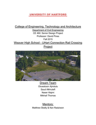
  • 7. 6 Existing Conditions A plan view of the proposed site of the connecting road is displayed in Figure 1 below. The photo displays the rail road on the east side between the University of Hartford and Weaver High School. The width of the rail road is approximately 20ft and is surrounded by shrubbery on either side. On the north side, parallel to both Hawk Drive and the rail road, are satellites and other utility devices surrounded by a chain link fence. The terrain, on which these utilities are located, range from 75ft to 71ft. Directly opposite from these utilities is a designated staff parking lot for residents of Village Quad 1, which can be see directly north of the parking lot. Figure 1 - Plan view of existing Hawk Drive and the site of the proposed connecting road and railroad tracks Situated between Hawk Drive and Mark Twain Drive are two maple trees that obstruct view to the railroad of motorists located at the intersection of the two roadways mention previously.
  • 8. 7 Finally, Parking Lot G is located in the south, which is used as general parking for staff and residents of the University of Hartford. The change in elevation is this location range from a high of 74 feet to a low of 63 feet. The Horizontal alignment of Hawk Drive has a radius of 130 degrees. At the proposed site of the connecting roads, the grades vary significantly. Generally, however, the elevation change from about 71 feet and the curve of Hawk Drive and 69 feet at the rail road. The photo below gives a better view of the terrain at the proposed site. The point of view displayed in the photo is from the apex of Hawk Drive’s curvature, and the location of the intersection of the proposed connecting road and Hawk Drive. Figure 2 - View from Hawk Drive of the proposed site for the connecting road Figure 3 below provides an indication of the existing Hawk Drive cross-section. The width of this existing road way is 24 feet in total, divided into two 12 feet lanes for opposing traffic. The outer edges of the roadway consist of bituminous concrete curbing 6 inches in width and height.
  • 9. 8 The surfacing consists of 6 inches of standard asphalt material and one foot of processed aggregate base underneath. There are currently no snow shelves or sidewalks on this existing portion of Hawk Drive. An existing catch basin, that is offset 6 inches from the curb, can also be viewed in the photo, near the intersection of Hawk Drive and Mark Twain Drive Figure 3 - View of the existing conditions of Hawk Drive The closest rail crossing to the proposed rail crossing is approximately 3100 feet south of the proposed design area. This railroad crossing is located on Plainfield Street, between Mark Twain Drive, and Granby Street.
  • 10. 9 Design Requirements and Constraints The safe design of an at-grade railroad crossing has additional challenges compared to a highway-highway intersection. While drivers can alter their path and speed over a short distance, trains are restricted to following a fixed path and changes in speed require much more time. To meet these unique requirements, the AASHTO “Green Book” – A Policy on Geometric Design of Highways and Streets was followed for the at-grade crossing, and geometric design of the connecting roadway. At the rail road crossing, both active (automatic gates and flashers) and passive devices (advance warning sign, pavement markers, and cross-buck) were used. In general, the main objective is to design a safe rail crossing that allows the driver to focus their attention to roadway conditions. The design requirements considered for the at-grade railroad crossing and adjoining roadway are: design speed, sight terrain, roadway elements and geometry, sight distance, layout and signage of the rail road crossing, as well as traffic analysis of existing and potential traffic demands. These are explained in more detail below.
  • 11. 10 Design Speed ● The posted speed of the connecting roadway is to be maintained at 15 mph - the current speed of the university road networks. The design speed, however, should be designed at least 5 mph higher for additional safety. Horizontal Alignment ● The UHart-Weaver connecting road should be perpendicular to the railroad track. The road must also intersect with the existing University road system at a right angle. A design speed of 20 mph allows for a minimum radius of curvature of 100 feet. Vertical Alignment ● Any sag vertical curves of the connecting roadway require a maximum k-value (rate of vertical curvature) of 7, and a maximum of 17 for any crest vertical curves. ● The elevation of the curve must coincide with existing grades at the point of intersections of the railroad crossing and Hawk Drive Sight Distance ● The required sight distance for horizontal curves of the design speed is 115 feet. ● The required sight distance for vertical curves at the design speed is also 115 feet. Width of Road ● According to the AASHTO “Green Book”, lane widths for urban and rural areas may be from 10 to 12 feet. 12 foot lanes should be used for roads designed for higher speeds. The University’s road widths are 12 feet as well. This creates uniformity in the alternative designs.
  • 12. 11 Side Walk  Sidewalks design shall be based on existing design criteria in order to maintain campus uniformity. Perpendicular Intersection with University Road  The rail road crossings are required to be perpendicular to railroad to the extend practical.  The crossing is required to not be placed on any curved sections of roadway or railway.  The level grade and material uniformity forming shall be maintained throughout the crossing. The dimensioning shall not be less the minimums specified in Figure 4 below: Figure 4 - Layout of Railroad-Highway Grade Crossing
  • 13. 12 Signage  Refer to Figure 5 below: Figure 5 - Rail Road Crossing Signage Requirements Change of Elevation  Where there is significant variation in terrain elevation, the proposed alignment should minimize cut and fill. This shall be done in order to minimize cost and maximize ease of construction.
  • 14. 13 Obstructions ● Existing utilities and trees should be avoided as much as possible. When traversing of utilities cannot be avoided, a 1-foot minimum clearance must be maintained. Legalities ● In the state of Connecticut, all at-grade rail crossings need a legislative approval to be built. ● The distance to the nearest rail road crossing needs to be determined. This will be considered in permitting approval since this will factored into the justifiability of the proposed crossing by the Department of Transportation (DOT).
  • 15. 14 Alternative Designs Four alternative designs were considered for the UHart-Weaver roadway connection. They include:  Tower Avenue – Hawk Drive Connection  3-Way Intersection of University, Hawk Drive, and Tower Avenue Extension  Tower Avenue Extension to Mark Twain Drive  Four-Way Intersection Connecting Mark Twain Drive, University Drive, Hawk Drive, and Tower Avenue Tower Avenue – Hawk Drive Connection The Tower Avenue – Hawk Drive Connection was presented to the team at the start of the project as part of the architect’s (SLAM Collaborative) renovation of Weaver High School (see Figure 6 below). The design forms a four-way intersection with Hawk Drive and the staff parking lot near Village Quad 1. The advantages of this design are that it is cost effective, and the constructability of the road is straight forward because it does not impact traffic on Hawk Drive. Figure 6 - Tower Avenue-Hawk Drive Connection
  • 16. 15 University, Hawk Drive, and Tower Avenue Extension 3-Way Intersection A 3-way intersection of University Drive, Hawk Drive, and Tower Avenue Extension was considered because it replaces the existing curve of University drive with one 3-way intersection (see Figure 7 below). This design was considered because it eliminates the close proximity of two 3-way intersections of the first alternative, and would provide for smooth traffic flow through the intersection. The cost of this design is more expensive than the direct Hawk Drive – Tower Road Extension connection road because of the offset and extension of Hawk Drive, which will involve more cut and fill, and the removal of obstructions (trees) to accommodate the design. Hence, the construction feasibility of this design is lower than the aforementioned. Figure 7 - University, Hawk Drive, and Tower Avenue Extension 3-Way Intersection
  • 17. 16 Tower Avenue Extension to Mark Twain Drive The third alternative considered was extending Tower Avenue Extension to Mark Twain Drive (see Figure 8 below). The extension of Tower Avenue will connect perpendicularly with Mark Twain Drive. Although the parking lot (G-Lot) in that area will be affected, this was the simplest design, and the design that provides the most stopping sight distance across the railroad. An advantage of design is the cost in relation to the other designs, and traffic flow will not interrupt traffic flow on University Drive and Hawk Drive. The elevation change in the design area would be a great concern with this proposed design. Thus, the cut and fill required would be greater than other proposed designs. The elevation in our proposed area changes from 74 feet to 63 feet. Figure 8 - Tower Avenue Extension to Mark Twain Drive
  • 18. 17 Four-Way Intersection Connecting Mark Twain Drive, University Drive, Hawk Drive, and Tower Ave. The last alternative design that was considered was creating a 4-way intersection. The 4-way intersection connects Mark Twain Drive, University Drive, Hawk Drive, and Tower Avenue (see Figure 9 below). This design is beneficial because it creates ‘green” space, or grass area. The traffic flow of this intersection is very intuitive. Of concern, however, is the rapid variation of elevations near G-Lot, which will require considerable cut and fill. In addition, the entire G-Lot in that area will eliminated to accommodate the shift of Mark Twain Drive at the 4-way intersection. Construction for this alternative design will affect university existing traffic greatly and will affect the operation of the campus Public Safety, which is located west of Mark Twain Drive. Thus, this is the most expensive alternative considered. Figure 9 - Four-Way Intersection Connecting Mark Twain Drive, University Drive, Hawk Drive, and Tower Ave.
  • 19. 18 Below is an alternative design matrix that the team created (see Figure 10 below). Each design was critiqued on the cost, intuitive traffic flow, parking, aesthetics and alternative space creation, and construction feasibility. The team deliberated on all alternative features and judged the crossings. Figure 10 - Alternative Design Matrix
  • 20. 19 Final Design While the design team proposed the Tower Avenue Extension to Mark Twain Drive as the most economical and efficient alternative, the overseeing committee comprising selected an alternative very similar to the Tower Avenue with Hawk Drive Connecticut, with a few minor adjustments. The Weaver Renovation Committee comprised of: management of the facilities department; SLAM Engineers; Freeman Companies Engineers; Hartford Schools Representatives; and other university officials. This alternative was chosen primarily because it maintains the original road circulation with minimum distraction. The alternative also has the advantage of minimizing the necessary cut and fill required, while providing sufficient minimum clearance required (200 feet) by the Manual on Uniform Traffic Control Devices (MUTCD) on either side of the crossing. To achieve this, the Hawk Drive radius was increased from 130 feet to 150 feet. On the Weaver High School property, the road aligns with a round-about that connects Tower Avenue with the connecting road. The design also included a sidewalk on the left side of the connecting road. The agreed upon preliminary design can be viewed in Figure 11 Below. Each of the design considerations are presented below.
  • 21. 20 Figure 11 - SLAM Preliminary Design
  • 22. 21 Design Speed A design speed of 20 mph was selected for the proposed connection. The design speed is 5 mph higher than the posted design speed to allow for a higher factor of safety. This accommodates motorists who may drive beyond the posted speed. The posted speed was maintained at the current speed in order to maintain uniform flow of traffic through the network, and to minimize the radius of curvature of the connecting roadway. The design speed has a direct impact on the subsequent considerations, such as the minimum rate of curvature, horizontal alignment, vertical alignments, stopping sight distance, etc. Horizontal Alignment Once the desgin speed was established, the proposed alignment was created in AutoCAD and over the course of the design, two design alternatives were considered based on SLAM’s original design: a 10 ft. North Offset; and a 60 ft. North Offset. These alternatives are presented in further detail on the following pages below.  10 ft. North Offset A view of the 10 ft. offset is displayed below in Figure 12. Contrary to the preliminary slam design, the connected road was shifted 10 ft. north to avoid the steep grades near G-Lot. The design team felt that this was necessary for the safety of road users and to minimize cost associated with cut and fill. The cost of the construction of a retaining wall surrounding G- Lot was also considered as a factor in the preliminary design as a means of supporting the soil underneath the roadway. The radius of curvature was maintained at 100 ft.
  • 23. 22 Figure 12 – 10 ft. North Offset 60 ft. North Offset The design team also considered placing sidewalks on both sides of the alignment in order to accommodate the anticipated pedestrian traffic on the roadway. Moreover, the addition of a sidewalk on the right side allows for more pedestrian safety since pedestrians will be required to cross the road when traversing west on Hawk Drive. This route is anticipated as the most likely rout since Public Safety and the academic side of the campus is locating in that direction. Creation of two pedestrian crossing at the intersection of Mark Twain Drive and Hawk Drive (one at the mouth of each street) in that regard. These suggestions will eliminate the need for the pedestrian crossing in the proposed slam concept that contains pedestrian crossings at acute angles across Hawk Drive, and near its connection to the proposed connecting road. The
  • 24. 23 disadvantage of this proposal is its encroachment on the location of the utilities near the sight. In addition, the adjustment shortened the length of the curve, reducing the amount of clearance available beyond the rail road crossing on the university side. A view of the 60 ft. North concept is displayed below in Figure 13. Figure 13 - 60 ft. North Offset After careful consideration, the team decided on the 10 ft. offset as the better option. All subsequent design considerations were based of that design concept. The final horizontal alignment increased the radius of Hawk Drive from 130 ft. to 150 ft. to accommodate the desired length of the connecting road, while meeting the minimum radius requirement. Thus, the
  • 25. 24 redesigned Hawk Drive alignment maintained that developed from the SLAM preliminary design concept. The redesigned section of Hawk Drive runs from a beginning station of 500+00 to an end station of 503+46. This redesign is located at the intersection of Hawk Drive to about 100 ft. beyond Village Quad 1 staff parking lot. The geometry of the alignment curve is specified in the Table 1 below: Station Direction Start Station End Station Delta Angle Chord Length Degree of Curvature by Arc PC N84⁰06’37E 500+00.00’ 500+45.09’ PI 500+45.09’ 502+92.46’ 94⁰29’16” 220.27 38⁰11’50” PT N10⁰22’39W 503+92.46’ 503+46.21’ Table 1 - Geometry of Hawk Drive Horizontal Alignment The connecting road was coined as Hart Drive and will be referred to as such from this point on. The baseline intersects Hawk Drive’s baseline at station 501+82. The length of the roadway is about 240 ft. long (0+00 to 3+50 total) and the design radius is at the minimum of 100 ft. The geometry of its vertical alignment curve is specified in Table 2 below:
  • 26. 25 Station Direction Start Station End Station Delta Angle Chord Length Degree of Curvature by Arc PC N54⁰04’17”E 0+00.00’ 1+12.42’ PI 1+12.42’ 2+25.29’ 64⁰40’15” 106.97 PT N61⁰15’28”E 2+25.29’ 3+50.00’ Table 2- Geometry of Hart Drive Horizontal Alignment The entire horizontal alignment can be viewed in the “Design Deliverables” section of the Appendix. Vertical Alignment The vertical alignment of the redesigned section of Hawk Drive consists of a single crest curve. The goal of the design was to minimize cut and fill by matching as closely as possible the existing vertical profile. The geometry of which can be view in Table 3 below: PI Station PVI Elevation Grade In Grade Out A (Grade Change) Profile Curve Type Profile Curve Length K- Value Curve Radius 0+00.00’ 64.41’ 4.50% 1+52.00’ 71.25’ 4.50% 1.24% 3.26% Crest 88.00’ 26.98 2698.47’ 3+46.21’ 73.65’ 1.24% Table 3 - Geometry of Hawk Drive's Vertical Profile.
  • 27. 26 The vertical alignment of Hart Drive consisted of two sag curves and two crest curves. The minimum k-values were exceeded for every curve and the slopes were attempted to be kept at 0.25 intervals for constructability purposes. Again, the alignment was designed to minimize cut and fill and to maintain constant level grade across the railroad tracks for at least 30 ft., thus exceeded the level grade requirements. Certain sections of the profile will require excavation to accommodate the designed alignment, however, there are sufficient areas to be filled in that will reduce the cost of earth transportation and disposal. The specified geometry of the final design vertical alignment can be viewed in Table 4 below: PI Station PVI Elevation Grade In Grade Out A (Grade Change) Profile Curve Type Profile Curve Length K- Value Curve Radius 0+14.00’ 71.11’ 0.50% 0+70.00’ 71.39’ 0.50% -1.49% 1.99% Crest 18.00’ 9.03 902.82’ 2+30.00’ 69.00’ -1.49% 0.00% 1.49% Sag 27.88’ 18.67 1866.67’ 2+74.00 69.00’ 0.00% 2.73% 2.73% Sag 50.00’ 18.31 1830.99’ 3+26.00 70.42 2.73% 1.25% 1.48% Crest 16.00’ 10.81 1080.53’ 3+50.00’ 70.72’ 1.25% Table 4 - Geometry of Hart Drive's Vertical Profile. All final vertical alignments of the designed roadway sections can be found in the “Design Deliverables” section of the Appendix.
  • 28. 27 Cross-Sections The cross-section of the both roadways were designed to be consistent with existing university road layout. The specifications are outlined below in table 5: Cross Section Location Travel Lane Width Snow Shelf Concrete Sidewalk Bituminous Concrete Lip Curb Grade from Crown Sidewalk/Snow- shelf Grade to Curb Hartt Drive 0+00’ to 3+30 12’ 4’ 5’ 6” 2.0% 2.0% Hawk Drive 500+09’ to 501+64’ 12’ 4’ 5’ 6” 2.0% 2.0% Hawk Drive 501+64’ to 503+46’ 12’ 4’ N/A 6” 2.0% 2.0% Table 5 - Specifications of Typical Cross-sections of Hart and Hawk Drive
  • 29. 28 Drainage For the connecting road, drainage shall consist of 4 catch basins (Type “C” single grate) at the point of lowest elevation on the vertical profile of Hart Drive Two catch basins will be at station 2+50 but offset on either side of the road crown (-11.5’ and +11.5’ from baseline). The other two catch basins will be at station 2+53 and will be offset in the same manner as the catch basins on the opposite side of the railroad tracks. The catch basin on Hawk Drive at station 0+80. will be used to collect and distribute the flow from Hart Drive by connected to the catch basin located on Hart Drive at station 2+50 and offset +11.5’. The catch basin on the opposite side of the road but at the same station will convey flow to this catch basin, which will convey the flow to Hawk Drive The catch basins on the Weaver side will be connected to their own unique system to avoid having to tear up the tracks. The connecting pipes used will be 1 ft. RCP, which were sized based on anticipated rainfall and accumulated time within the catchment areas near the vicinity of the catch basins. The piping used was also designed to avoid any utility pipes in its path by at least 1 ft., and on the assumption that the utility pipes are of the standard 1ft diameter. The drainage storm computation sheet used to size the pipes can be found in the appendix under design calculations. The catch basins designs are given in tables 6 and 7 below:
  • 30. 29 Street Station Offset Type Top of Frame (ft) Invert In (ft) Invert Out (ft) Sump (ft) Hart Drive 2+50 -11.5 “C” Single Grate 69.00 ------------- 66.00 62.00 Hart Drive 2+50 +11.5 “C” Single Grate 69.00 65.64 65.54 61.54 Hawk Drive 0+80 +11.5 “C” Single Grate 68.00 58.36 58.26 54.26 Table 6 - Catch Basin Design
  • 31. 30 Railway Crossing Design Specifications Signage Based on the requirements of the MUTCD Manual, the proposed rail crossing will need one crossbuck on the right side of each approach. The front and back of the crossbuck support needs a vertical piece of retroflective tape, no less than two inches. Crossbucks usually have a number plaque, displaying how many tracks are at the crossing. A number plaque will not be necessary at this crossing because the there is only one track at the crossing. Also, because the rail is “Low Rail Traffic” (LRT), the rail crossing does not need a stop sign on either side of the approach. The rail crossing can omit a stop sign because the speed of the train does not exceed 25 mph (8B.05). The rail crossing will need a “Do Not Stop On Tracks” sign, which is required at every rail crossing. Figure 14: "Do Not Stop On Tracks" Sign Control Devices For the final design of the rail crossing, the rail crossing needs flashing light signals. The rail crossing will need two flashing light signals, attached to the crossbuck support. A pair of flashing lights can be mounted underneath the crossbuck.
  • 32. 31 Figure 15: Railroad Crossing Crossbuck Gates Along with the flashing lights, the lane gate should also be attached to the support for this design. There will be a lane gate for both approaches. Each gate will have 3 flashing lights on the top of the gate and will work in unison with the flashing lights mounted on the crossbuck support. Due to the width of the road, a cantilever beam with flashing lights is not needed here in this crossing design. The end of the gate should span over the lane and reach the crown of the road. In the downward position, the gate is to be suspended over the road vertically between 3.5 and 4.5 feet. On the left side of the final alignment, there will be a pedestrian gate. A pedestrian gate ensures that once a train is coming, the gate will restrict any person from crossing the tracks. The safety of the pedestrians using the crossing is the biggest priority. The crossing will also be equipped with an audible device due to having pedestrians use this crossing. The gates and flashing lights will be mounted 15 feet from the centerline of the track. MUTCD strongly advises that a bell be installed and used in conjunction with the flashing lights. The figures below show the requirements for the traffic control devices, including dimensions and measurements of the devices.
  • 33. 32 Figure 16 - Example of a Rail Crossing Gate and Pedestrian Gate Figure 17 – Minimum Distance of Rail Crossing Gate
  • 34. 33 Road Markings A stop line for road should be placed at 15 feet from the rail road tracks. The MUTCD manual recommends that the minimum distance between the start of the track and the start of the stop line will should be 12 feet. There also must be a distance of 50 feet before the second yield line, which starts the pavement marking symbol. The design width of the road is 12 feet, which changes the design of the pavement marking symbol for the railroad. The figure below shows the railroad crossing marking on the pavement and the different dimensions of the markings.
  • 35. 34 Figure 18 - Railroad Crossing Pavement Marking
  • 36. 35 Panels For the final design, the team has decided on choosing rubber panels for the railroad crossing. Rubber panels will be inserted 3 inches before, 3 inches after and 36 inch panels will be inserted in-between the railroad tracks. There was an option of choosing asphalt, concrete or wooden panels. Rubber panels were the best choice for this rail crossing because it is weather and chemical resistant, which eliminates rail-crossing maintenance. The rubber panels interlocks with one another, which is designed to seal out debris and moisture. With concrete and wood, there is a chance of cracks and fractures of the material due to weather and loading of the vehicle that ride over the rail crossing. But with rubber panels, the panels are 100% flexible rubber. Also, rubber panels have high electrical resistance, making it safe, and eliminating signal shunting. The figure below shows an example of rubber panels used at a rail crossing. Figure 19 - Example of Rubber Panels for Rail Crossing
  • 37. 36 Traffic Analysis Synchro 9 software was used to analyze how the UHart-Weaver connection road would impact the existing intersection of Mark Twain Drive and Hawk Drive; but primarily to determine whether the queue length generated on the new Hart Drive will extend to the railroad crossing. In the Hawk Drive connection design there was only one stop sign on the new connection. However, to create a report in Synchro 9 software, the group was required to add a stop sign on the northeast bound of Hawk Drive & the new connection intersection to get the 95th percentile queue length. That shouldn’t make a difference because the number of cars, which will come from this approach is relatively small (no more than 100 vehicles during the peak hour depending on the traffic counts that were done in November 2014). The location of the existing stops signs is identified in Figure 20 below, while the additional stop sign required for synchro analysis is found in Figure 21. Synchro 9 lacks the minor details such as sidewalks and other roadway detailing. Curvatures are also difficult to draw by Synchro 9, unlike the AutoCAD curve radii can simply be specified and created by the click of a button. However, these minor details do not significantly impact the results generated by the Analysis Software. To compensate for these minor issues, the peak hours selected were emphasized dramatically to determine adequacy of the road length.
  • 38. 37 Figure 20 - Existing Stop Signs on Hawk Drive Figure 21 - Location of Stop Signs Required in the Traffic Analysis Software
  • 39. 38 For the traffic analysis, the design team used traffic counts through all possible intersections that could affect the Uhart-Weaver connection. The traffic counting was provided by Innovative Data, LLC on their website. The traffic counting was done on Tuesday, November 18th, 2014 for both AM and PM peak. The intersections were Granby Street at Tower Ave, Mark Twain Ave at University Drive, and Route 189 at University Drive The results for these intersections are shown in Table 7. The results showed that during the AM peak, the total volume was 130 vehicles, and the total volume for the PM peak was 63 vehicles. For that, the group assumed the range for the proposed volume to be between 20 – 100 vehicle per lane during the peak hours, or in other words, 40 and 200 vehicles during the peak hours. Two AM proposed demands (20 and 100 vehicles per lane) and two PM proposed demands (20 and 100 vehicles per lane) were used in the analysis. Table 8, shows the Queue length of the 95th percentile and LOS (Level of Service) for all the approaches of Hawk Drive at Hart Drive As can be viewed in the table, the queue length generated on Hart Drive was 25ft. which is much less than the 240 ft. length of Hart Drive Therefore, no pile ups extended across the rail road crossing is anticipated. Mark Twain From North University From East Mark Twain From South University From West Start time Right Thru Left Right Thru Left Right Thru Left Right Thru Left Total 7:15 0 0 0 0 0 0 0 0 1 1 0 0 2 7:30 0 0 0 0 0 0 1 0 2 1 1 0 5 7:45 0 0 0 0 0 0 0 0 2 1 0 0 3 8:00 0 0 0 0 0 0 0 0 0 2 0 0 2 Total 0 0 0 0 0 0 1 0 5 5 1 0 12
  • 40. 39 Granby From North Tower From East Granby From South Tower From West Start time Right Thru Left Right Thru Left Right Thru Left Right Thru Left Total 4:00 0 0 2 3 0 0 0 1 0 0 0 0 6 4:15 0 3 0 1 0 1 1 2 0 0 0 0 8 4:30 0 0 1 0 0 0 0 1 0 0 0 0 2 4:45 0 2 2 1 0 0 0 4 0 0 0 0 9 Total 0 5 5 5 0 1 0 8 0 0 0 0 25 Mark Twain From North University From East Mark Twain From South University From West Start time Right Thru Left Right Thru Left Right Thru Left Right Thru Left Total 4:00 0 0 0 0 0 0 0 0 0 0 0 0 0 4:15 0 0 0 0 0 0 0 0 0 0 0 0 0 4:30 0 0 0 0 0 0 0 0 0 0 0 0 0 4:45 0 0 0 0 0 0 0 0 0 0 0 0 0 Total 0 0 0 0 0 0 0 0 0 0 0 0 0 Route 189 From North University From East Rout 189 From South University From West Start time Right Thru Left Right Thru Left Right Thru Left Right Thru Left Total 4:00 0 7 0 4 0 8 1 3 0 0 0 0 23 4;15 0 0 1 1 0 3 0 2 0 0 0 0 7 4:30 0 1 0 0 0 0 0 1 0 0 0 0 2 4:45 0 2 0 0 0 1 0 3 0 0 0 0 6 Total 0 10 1 5 0 12 1 9 0 0 0 0 38 Granby From North Tower From East Granby From South Tower From West Start time Right Thru Left Right Thru Left Right Thru Left Right Thru Left Total 7:15 0 1 0 3 0 1 0 5 0 0 0 0 10 7:30 0 1 3 1 0 1 1 8 0 0 0 0 15 7:45 0 6 0 0 0 0 0 8 0 0 0 0 14 8:00 0 0 1 2 0 1 1 9 0 0 0 0 14 Total 0 8 4 6 0 3 2 30 0 0 0 0 53
  • 41. 40 Route 189 From North University From East Rout 189 From South University From West Start time Right Thru Left Right Thru Left Right Thru Left Right Thru Left Total 7:15 0 5 1 0 0 0 1 6 0 0 0 0 13 7:30 0 8 0 1 0 1 0 14 0 0 0 0 24 7:45 0 4 0 2 0 1 1 4 0 0 0 0 12 8:00 0 6 0 0 0 1 0 9 0 0 0 0 16 Total 0 23 1 3 0 3 2 33 0 0 0 0 65 Table 7 - AM & PM Peak Hours used in Traffic Analysis AM PM Existin g Proposed2 0 Proposed10 0 Existin g Proposed2 0 Proposed10 0 Mark Twain Dr & University Dr @ Hawk Dr - - - - - - Northboun d LOS A LOS A LOS A LOS A LOS A LOS A Westbound LOS A LOS A LOS A LOS A LOS A LOS A Eastbound LOS A LOS A LOS A LOS A LOS A LOS A Hawk Dr @ Hart Dr - - - - - - Northeast bound N/A 5ft/LOS A 20ft/LOS B N/A 15ft/LOS A 35ft/LOS B Westbound N/A 5ft/LOS A 25ft/LOS B N/A 5ft/LOS A 25ft/LOS B Southwest bound N/A 0ft/LOS A 0ft/LOS A N/A 0ft/LOS A 0ft/LOS A Table 8 - Sumary of Traffic Analysis
  • 42. 41 Opinion of Cost The cost of this project was divided into two main sections: road construction costs and the rail road crossing cost, which includes materials and signage. The approximated costs were $500,000 for road and $400,000 for the rail road crossing. A detailed cost estimate can be found on the following page.
  • 43. 42
  • 48. 47 Meeting Minutes 9/8/15 Transportation ● Different alternatives ● University Of Hartford ● Permits, permission, restraints ● Best Alternatives will be chosen ● Design ● Vertical and Horizontal Alignment ● Drainage (Catch Basins) ● Intersection ● Site Design ● Class Meeting once a week and meeting with mentor once a week 9/10/15 Type Study ● Length of construction ● Looks good (very important) ● Money ● Drawing ● Convincing Public that this is needed Transportation ● Traffic analysis and Roadway Design ● How are people going to use this connection? ● Permitting ● Pavement design, HA, VA, drainage issue Getting Started ● Writing a Proposal ● Project understanding & scope of services (bullet points) ● Time sheets (Tracking your hours) ● Due 9/15/15 (Tuesday)
  • 49. 48 9/15/15 Meeting Topics ● Auto CAD ● Conceptual Ideas ● AASHTO Alternatives ● Requirements/Constraints (UHart) ● Cost Estimate To Do’s ● Task 1- Research ● Document the site ● Existing condition ● Permitting (required) ● Base Data (Mapping)/ Traffic Counts ● Codes & Requirements ● AASHTO or DOT ● Location of Site ● Task 2- Alternative Design Analysis ● 2 at-grade alternatives ● Speed Limit ● Pedestrian Pathways ● Intersection Design ● Task 3 ● H.A. and V.A. ● Railroad Crossing ● Drainage System ● Midterm= Present to F&O ● Curbs or no curbs ● Intersection ● Payment Design ● Task 4 ● Operation ● Cost Estimate ● Const. Schedule ● Drafting
  • 50. 49 ● Task 5 ● Report ● Presentation/Poster ● Managing Project
  • 51. 50 9/22/15 To Do List ● Permitting ● Base Data from facilities ● Common Ground meeting with Bridge Group Notes ● Scope of services ● UHart (Owner) ● Hours- multiply by the number of people working on the assignment/task ● Project Management ● Entire time of project ● Once a week ● Meeting w/ Mentor once a weeks ● Pick 60% or 70% Design ● Find Traffic study of the entire university (Facilities or Fuss & O’Neil) ● City of Hartford website ● Engineering office ● Road requirements ● Send Both proposal to Drive Pines and Matt (Thursday @ 4) ● Agenda for meeting w/ Matt ● Design and Build to the future (Pedestrian access)
  • 52. 51 9/24/15 Fuss & O’Neil ● Send everything in a PDF File ● Need a Green Book ● Highway Design Manual Scope of Services ● Spec Book ● General Description of all work done ● Come up with a item ● Paving, curbing, striping ● DOT standard cost (ConnDOT) ● Base Map from Matt ● Regional Traffic/Local Traffic Pattern ● Tower Ave may be abandoned and became Parking lot ● Construction Staging ● Equipment Location ● Parking lot on the right of public safety ● Signage: Const. & permanent (look into MUTCD) ● Google Earth- Railroad Crossing ● Const. Phasing ● 3 months- After Graduation and before school ● OSHAA (aware) ● UHart- Major Traffic generator ● Traffic Counts (Matt) Alternative Design ● 2 Alt Design at-grade ● Cut and fill? ● Sidewalk on University Drive ● CAD Drawings
  • 53. 52 10/6/15 Senior Design ● Signage at a railroad crossing ● Design Requirements (ConnDOT) ● Hand draw 3 Alternatives by 10/13 ● Meeting with Matt on the 15th 10/13/15 ● Design: Site Design ● Gate ● Account for pedestrians ● Design Speed: 15mph ● Road Curvature design for higher speed (25mph to 30 mph) ● Check the topography in the area ● Parking Lot entrance in Quad 1 ● Compare curvature of Hawk Drive ● How much cut and fill is required? ● Green Book Page 388 ● RR-Highway Grade Crossing ● Chapter 9
  • 54. 53 10/15/15 October 27- Presentation to the University Agenda ● Updates ● Rail Traffic Crossing (MUTCD) ● 1 inch of pitch for 30 feet ● Proper crown (water drainage) ● Green Book ● Good intersection site design ● Trees may be hindrance (12in) ● Requirements for clear site distance ● Manual of Uniform Traffic Control ● Ask Home Depot about train Service ● Final Train Report (Low Volume Train) ● Make request to Hartford PD for crash history in design area ● Design ● 4-way intersection ● Side image of Google Earth & AutoCAD drawing ● SLAM ● Make the intersection perpendicular with train ● Move Parking lot G and move it next to PS ● Thru Moment (Hawk Drive to Weaver) ● Thursday, Oct 22nd (Matt @ UHart) ● Design #3- Roundabout? ● Presentation for Tuesday ● 20 minutes ● Objectives/Goals ● Owner Requirements ● Design Codes, Requirement, Constraints ● Green Book, AASHTO ● Alternatives ● Pros, Cons ● Make Recommendation ● Make a Criteria Matrix
  • 55. 54 11/3/15 ● Clients picked a design ● Option 1 (Prelim Design) ● Don’t Want road to be publicly used ● Focus design of the road across the railroad tracks ● Min req by MUTCD on road length (200’) ● Length of road- 240’ ● To-Do ● HA & VA ● Check site line/ site distance ● Check grade in the area ● Catch basin/Drainage Design ● Railroad Crossin Signal System ● Construction Sequence ● Cost Estimation ● Design Sidewalks for snow as well ● Show cut and fill for profile ● Material of sidewalk (Asphalt) ● Come up w/ a decision on the gates
  • 56. 55 11/5/15 ● Ken- New Alignment needs to be drawn in 1. Come up w/ Alignment a. AASHTO and Green Book b. Design for larger speeds 2. Curb Radii a. Sidewalks b. Road (actual look) 3. Cross Section of Road ● Produce profile for roadway ● Option of going to Fuss & Oneil to work on profile (Civil 3D) ● 3 Lines –Poly, Construction, line ● Design Speed ● 25 mph, Design Speed-> actually 20 mph ● E- superelevation- constant cross slope ● Min Radius= 181 ft → 200ft ● For Next Week ● Plan View of Cross Section ● HMA.5→ Asphalt ● HMAS1→ Larger aggregate 11/10/15 ● Catch Basin Design ● How many? Where? ● Elevation in the existing area ● Minimize cut and fill 11/12/15 ● Recap of due dates
  • 60. 59
  • 61. 60
  • 62. 61
  • 63. 62
  • 64. 63