Unmanned Ground Vehicle
•Descargar como PPT, PDF•
23 recomendaciones•16,177 vistas

Final Year Engineering Project Seminar For more information, check out my papers online: Command controlled robot: http://www.ijtre.com/manuscript/2014010976.pdf Self controlled robot: http://www.ijtre.com/manuscript/2014011008.pdf Gesture controlled robot: http://www.ijtre.com/manuscript/2014011107.pdf

Recomendados
Más contenido relacionado
La actualidad más candente
La actualidad más candente (20)
Destacado
Destacado (19)
Similar a Unmanned Ground Vehicle
Similar a Unmanned Ground Vehicle (20)
Más de Mithileysh Sathiyanarayanan
Más de Mithileysh Sathiyanarayanan (20)
Último
Último (20)
Unmanned Ground Vehicle
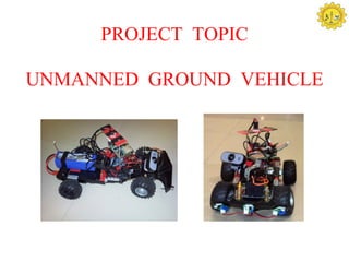
- 1. PROJECT TOPIC UNMANNED GROUND VEHICLE
- 3. WHAT IS AN UNMANNED GROUND VEHICLE ? •An Unmanned Ground vehicle (UGV) is a robot used to augment human capability in both civic and military activities in open terrain. •It is used as a human replacement in several dangerous military operations such as handling explosives, diffusing bombs and front line reconnaissance. •There are two general classes of unmanned ground vehicles - Tele operated Autonomous
- 4. PROJECT ABSTRACT Command Centre Control mode : • Maneuver the UGV wirelessly by transmitting navigation commands from the base station based on the video received from the on-board camera. • Control the turret wirelessly in order to locate and eliminate targets in the field of vision. ARMCON mode : • Control the UGV using commands sent based on hand movements mapped by the IMU unit Autonomous mode : • Capable of travelling from point A to point B without human navigation commands. • Adjust strategies based on surroundings using obstacle detection algorithms. Raptor mode : • Locate and eliminate targets in the field vision using motion tracking. • Motion tracking implemented through advanced image processing algorithms.
- 5. Components Description Arduino Microcontroller: •Microcontroller: ATMega328 •Operating Voltage: 5V •Input Voltage (recommended): 7-12V •Digital I/O Pins: 14 (6 for PWM output) •Analog Input Pins: 6 •Flash Memory: 32 KB (1/2 KB boot-loader) •Power supply: USB, barrel connector, battery •Advantages: ease of programming, inbuilt boot-loader, ease of communication
- 6. GPS Module: To obtain position co-ordinates Weight: 16g including cable • 30 Healthy satellites in orbit • Extremely high sensitivity 20m Positional Accuracy Magnetic compass: •Simple I2C interface •2.7 to 5.2V supply range •1 to 20Hz selectable update rate •0.5 degree heading resolution •Supply current : 1mA at 3V
- 7. ZIGBEE (X-Bee Pro series 2): Range : Up to 2 miles. Operating Frequency – 2.4 GHz • Power Output – 50mW • Operating Power – 3-3.4V, 300mA Inertial Measurement Unit (IMU): •Obtain pitch, roll and yaw values •Contains three axis accelerometer providing changes in the current acceleration due to gravity.
- 8. SERVO motor: •Electro-mechanical device •Shaft angle proportional control based on electrical signal •0 – 180 degrees motion •Extensive applications in robotics, airplanes, RC cars, etc. Li-Po Battery: •Current Capacity: 5000mAH •Configuration: 18.5V, 5 Cell • Pack weight : 666 gm • Pack Size : 149 x 48 x 42 mm
- 9. COMMAND CENTRE CONTROL (Mode -1) LIVE VIDEO FEED TURRET KEYBOARD COMMAN UGV ARDUINO USER D CENTRE ON BOARD RELAY CONTROLLER (SYSTEM) SYSTEM Power SERVO MOUSE Supply(Li- MOTOR Po) H-BRIDGE Regulator Circuit INTERNET DC MOTOR BLOCK DIAGRAM
- 10. Algorithm Design : User side :- • Keys for rover movement • Their equivalent translation to the arduino controller. • The operation being executed are as shown. Key Character sent Objective Pressed Up U Forward Down D Reverse Left L Turn left Right R Turn right Ctrl 0 Stop UGV side :- • UGV monitors serial input for the received characters and makes the subsequent decisions. • Execution of up(), down(), left(), right(), halt() • Clockwise and anticlockwise pin assignment for forward and reverse. • Separate PWM pin for 80 -120 degrees range of servo turn, H- Bridge Enable control for braking.
- 11. FLOW CHART Base station UGV Control Control From command Command Centre control Centre system – Selects Manual mode User defined input - up, Monitoring serially sent down, left, right, control control Signals- U,D,L,R,0 Control signals sent- Equivalent functions run- U,D,L,R,0 up(), down(), right(),left(),halt() Respective pins are set To UGV high to control movement System and turn
- 12. Autonomous Mode (MODE – 2) GPS IR Sensors UGV MOTION Base ARDUINO station DC & USER and On H-Bridge Servo Controlle board motors r system Power MAGNETIC Supply(Li- COMPASS Po) Regulator Circuit BLOCK DIAGRAM
- 13. Algorithm Design: Obtain the Current GPS co-ordinates and the heading reading from the Compass. Obtain the Destination Co-ordinates from the user. Calculate the angle by which the UGV orients with the desired direction. Calculated angle provides the rover movement control signals. The UGV navigates itself to the desired location based on the IR sensors values which are obtained with respect to the obstacles. IR(L) IR(M IR(R) Operations IR(L) IR(M IR(R) Operations ) performed ) performed 1 0 0 Right() and 0 0 0 (No obstacles) Up() 0 0 1 Left() and Up() 1 0 1 Up() 0 1 0 Random[Right() 1 1 0 Right() and or Left()] and Up() Up() 1 1 1 Random[Right() 0 1 1 Left() and Up() or Left()] and down()
- 14. FLOW CHART Command Centre- Selects Autonomous Mode Perform necessary Destination reached obstacle avoidance with some exceptions using set of IR values Obtain current location and Obtain current destination from angle from compass Simultaneously monitor user the IR sensor values (obstacles) Calculate distance, Calculate difference heading. angle Decision on navigation based on difference angle
- 15. ARMCON - IMU Controlled (Mode -3) UGV MOTION Power Supply(Li- H-Bridge NI-CD ARDUINO X-BEE BATTERY CONTROLLER PRO S2 Po) (DC & SERVO Regulator MOTORS) Circuit UGV ON IMU X-BEE PRO S2 BOARD Arduino SYSTEM BLOCK DIAGRAM
- 16. Algorithm Design: ARMCON side :- • Provides pitch and roll values based on the inclination along x and y axis. • Assumed range 30+ along both directions(+ve & -ve). • Values serially monitored and transmitted by arduino and zigbee respectively. Range Character Objective sent Pitch > 30 F Forward Pitch < -30 B Reverse Roll > 30 R Right Roll < -30 L Left -30<= pitch 0 Stop >=30 UGV side:- -30<= roll >=30 • Execution of up(), down(), left(), right(), halt() • Clockwise and anticlockwise pin assignment for forward and reverse. • Separate PWM pin for 80 -120 degrees range of servo turn. • H- Bridge Enable control for braking
- 17. FLOW CHART ARMCON SIDE UGV SIDE Command Centre: Selects Up(), down(), right(), IMU mode left(), halt() for rover movements Pitch and roll variations of Controls signals the IMU translated to equivalent functions Controls signals for pitch Received by the X-bee and roll- f,b,r,l,0 and stored Serially communicated to From the X-Bee ARMCON Setup To UGV
- 18. RAPTOR MODE (MODE – 4) COMMAN ON ARDUINO USER D CENTER BOARD TURRET CONTROLLER SYSTEM SYSTEM Power Supply(Li- Po) BLOCK DIAGRAM Regulator Circuit
- 19. Algorithm Design: Image frame f1 acquisition at time T1. Image frame f2 acquisition at time T2. T2>T1 , markers placed in both the frames at preset locations. Both the frames after marking are compared , and the location of the pixel at a marker in f1 is found in the neighborhood of the same marker in the f2. If there is a match, a vector is drawn from marker to the new location of the pixel determined. The above steps are repeated for the all the markers. The magnitude and direction of the vector is used in to Fig: Vector flow diagram of rotating find the direction of motion of the pixel in the image object and the decision to move the turret position is made on the basis of the observed data.
- 20. FLOW CHART Command Centre- Selects Raptor mode Stop if IMAGE ACQUISITION Raptor Mode Deselected MARKERS ARE PLACED AT PRESET LOCAITONS THE POSITION TO Direction of Equivalent turret image flow WHICH TURRET TO movement to track the determined motion of the object BE MOVED IS COMPUTED
- 21. Applications Reconnaissance . Bomb disposal. Search and rescue. Border patrol and surveillance. Active combat situations. Stealth combat operations. New explorations. To undertake dangerous missions which involves loss of human life.
- 22. RESULT: Successfully built a stand-alone rover capable of both manual and autonomous modes of control. Added a rotating camera platform that can target the enemy with/without human control. Successfully implemented features including motion tracking, obstacle detection, path planning , gesture control and GPS. CONCLUSION: The incorporation of various technologies under one roof has given us the path to achieve goals which have never been realized in such an efficient manner in the past. These technologies bring about a self relying and able machine to tackle situations on its own and ease a human’s job in the present day scenarios.
- 23. FUTURE ENHANCEMENTS • Additional sensors such as Passive infrared sensors, thermal imaging, Gas sensor, can be added to enhance the capabilities of the UGV. • Optical flow augmented with other image processing algorithms such as frame differencing, edge detection to accomplish more reliable motion tracking. • High end technology with higher resolving capabilities can be added to enhance the present functionality of the UGV. • Secure satellite links for communication increases the security of UGV operation.
- 24. References and Papers Books: Rafael C. Gonzalez and Richard E. Woods, “Digital Image Processing,” 3rd ed., PHI Learning, 2008. Papers: K.K.Soundra Pandian Member, IAENG and Priyanka Mathur,”Traversability Assessment of Terrain for Autonomous Robot Navigation, “Proceedings of the International MultiConference of Engineers and Computer Scientists 2010 Vol II, IMECS 2010, March 17-19, Hongkong, ISBN: 978-988-18210-4-1. Saurav Kumar and Pallavi Awasthi, “Navigation Architecture for Autonomous Surveillance Rover,” International Journal of Computer Theory and Engineering, Vol. 1, No. 3, August, 2009,1793-8201, Pg. 231-235. Mohd Azlan Shah Abd Rahim and Illani Mohd Nawi, “Path Planning Automated Guided Robot,” Proceedings of the World Congress on Engineering and Computer Science 2008, WCECS 2008, October 22 - 24, 2008, San Francisco, USA, ISBN: 978-988-98671-0-2. Boyoon Jung and Gaurav S. Sukhatme, “Real-time Motion Tracking from a Mobile Robot,” International Journal of Social Robotics, Volume 2, Number 1, 63-78, DOI: 10.1007/s12369-009-0038-y Wenshuai Yua, Xuchu Yub, Pengqiang Zhang and Jun Zhou, “A New Framework of Moving Target Detection and Tracking for UAV Video Application,” The International Archives of the Photogrammetry, Remote Sensing and Spatial Information Sciences. Vol. XXXVII. Part B3b. Beijing 2008
- 25. THANK YOU