SlideShare una empresa de Scribd logo
1 de 142
Descargar para leer sin conexión
A1800 ALPHA Meter
Technical Manual
Rev.02
10-2011
www.izmerenie.ru
Technical manual i Contents
Contents
1 Introduction . . . . . . . . . . . . . . . . . . . . . . . . . . . . . . . . . . . . . . . 1-1
A1800 ALPHA meter . . . . . . . . . . . . . . . . . . . . . . . . . . . . . . 1-1
Standards Compliance . . . . . . . . . . . . . . . . . . . . . . . . . . 1-2
IEC . . . . . . . . . . . . . . . . . . . . . . . . . . . . . . . . . . . . . . . . 1-2
IEEE/ANSI . . . . . . . . . . . . . . . . . . . . . . . . . . . . . . . . . 1-2
DIN . . . . . . . . . . . . . . . . . . . . . . . . . . . . . . . . . . . . . . . 1-2
Benefits . . . . . . . . . . . . . . . . . . . . . . . . . . . . . . . . . . . . . . 1-3
Reliability . . . . . . . . . . . . . . . . . . . . . . . . . . . . . . . . . . 1-3
Maintainability . . . . . . . . . . . . . . . . . . . . . . . . . . . . . . . 1-3
ANSI standard communication open protocol . . . . . . 1-4
Adaptability . . . . . . . . . . . . . . . . . . . . . . . . . . . . . . . . . 1-4
Economy . . . . . . . . . . . . . . . . . . . . . . . . . . . . . . . . . . . 1-4
Security . . . . . . . . . . . . . . . . . . . . . . . . . . . . . . . . . . . . 1-4
Accuracy . . . . . . . . . . . . . . . . . . . . . . . . . . . . . . . . . . . 1-4
Meter types . . . . . . . . . . . . . . . . . . . . . . . . . . . . . . . . . . . . . . 1-5
Meter series . . . . . . . . . . . . . . . . . . . . . . . . . . . . . . . . . . . 1-6
2 Product description . . . . . . . . . . . . . . . . . . . . . . . . . . . . . . . . . 2-1
Physical description . . . . . . . . . . . . . . . . . . . . . . . . . . . . . . . . 2-1
Optical port . . . . . . . . . . . . . . . . . . . . . . . . . . . . . . . . . 2-3
LCD . . . . . . . . . . . . . . . . . . . . . . . . . . . . . . . . . . . . . . . 2-3
Nameplate . . . . . . . . . . . . . . . . . . . . . . . . . . . . . . . . . . 2-3
Utility information card . . . . . . . . . . . . . . . . . . . . . . . . 2-4
Communications . . . . . . . . . . . . . . . . . . . . . . . . . . . . . 2-4
Battery . . . . . . . . . . . . . . . . . . . . . . . . . . . . . . . . . . . . . 2-5
Cover tamper detection switches . . . . . . . . . . . . . . . . . 2-5
Terminal configurations . . . . . . . . . . . . . . . . . . . . . . . . 2-6
Communication protocols . . . . . . . . . . . . . . . . . . . . . . . . . . . 2-6
System architecture . . . . . . . . . . . . . . . . . . . . . . . . . . . . . . . . 2-6
General theory of operation . . . . . . . . . . . . . . . . . . . . . . . . . . 2-7
Power supply . . . . . . . . . . . . . . . . . . . . . . . . . . . . . . . . . . 2-7
Main power supply . . . . . . . . . . . . . . . . . . . . . . . . . . . 2-7
Auxiliary power supply . . . . . . . . . . . . . . . . . . . . . . . . 2-7
Current and voltage sensing . . . . . . . . . . . . . . . . . . . . . . 2-7
Meter engine . . . . . . . . . . . . . . . . . . . . . . . . . . . . . . . . . . 2-8
Microcontroller . . . . . . . . . . . . . . . . . . . . . . . . . . . . . . . . 2-8
EEPROM . . . . . . . . . . . . . . . . . . . . . . . . . . . . . . . . . . . . 2-8
Billing data . . . . . . . . . . . . . . . . . . . . . . . . . . . . . . . . . . . . . . 2-9
Metered energy and demand quantities . . . . . . . . . . . . . 2-9
Average power factor . . . . . . . . . . . . . . . . . . . . . . . . . . . 2-9
Demand calculations . . . . . . . . . . . . . . . . . . . . . . . . . . . . 2-9
Rolling interval . . . . . . . . . . . . . . . . . . . . . . . . . . . . . 2-10
Block interval . . . . . . . . . . . . . . . . . . . . . . . . . . . . . . . 2-10
Thermal time constant . . . . . . . . . . . . . . . . . . . . . . . . 2-11
Maximum demand . . . . . . . . . . . . . . . . . . . . . . . . . . . . 2-11
Cumulative maximum demand . . . . . . . . . . . . . . . . . . . 2-11
Continuous cumulative maximum demand . . . . . . . . . 2-11
Coincident demand or power factor . . . . . . . . . . . . . . . 2-12
Contents
Technical
manual
Technical manual ii Contents
Demand forgiveness . . . . . . . . . . . . . . . . . . . . . . . . . . . 2-12
Primary and secondary metering . . . . . . . . . . . . . . . . . 2-12
TOU data . . . . . . . . . . . . . . . . . . . . . . . . . . . . . . . . . . . . 2-12
Power failure data . . . . . . . . . . . . . . . . . . . . . . . . . . . . . 2-13
Logs and data sets . . . . . . . . . . . . . . . . . . . . . . . . . . . . . . . . 2-13
Event log . . . . . . . . . . . . . . . . . . . . . . . . . . . . . . . . . . . . 2-14
History log . . . . . . . . . . . . . . . . . . . . . . . . . . . . . . . . . . 2-14
Self reads . . . . . . . . . . . . . . . . . . . . . . . . . . . . . . . . . . . . 2-14
Load profiling . . . . . . . . . . . . . . . . . . . . . . . . . . . . . . . . 2-15
Load profiling pulse divisor . . . . . . . . . . . . . . . . . . . . 2-15
Instrumentation profiling . . . . . . . . . . . . . . . . . . . . . . . 2-16
TRueQ Log . . . . . . . . . . . . . . . . . . . . . . . . . . . . . . . . . . 2-17
Voltage sag log . . . . . . . . . . . . . . . . . . . . . . . . . . . . . . . 2-17
User-defined tables . . . . . . . . . . . . . . . . . . . . . . . . . . . . 2-17
Physical dimensions and mass . . . . . . . . . . . . . . . . . . . . . . 2-18
3 Operating instructions . . . . . . . . . . . . . . . . . . . . . . . . . . . . . . . 3-1
Indicators and controls . . . . . . . . . . . . . . . . . . . . . . . . . . . . . 3-1
LCD . . . . . . . . . . . . . . . . . . . . . . . . . . . . . . . . . . . . . . . . . 3-1
Quantity identifier . . . . . . . . . . . . . . . . . . . . . . . . . . . . 3-2
Display quantity . . . . . . . . . . . . . . . . . . . . . . . . . . . . . . 3-2
Phase indicators . . . . . . . . . . . . . . . . . . . . . . . . . . . . . . 3-2
Energy direction indicators . . . . . . . . . . . . . . . . . . . . . 3-2
Power/energy units identifier . . . . . . . . . . . . . . . . . . . . 3-3
Alternate display indicator . . . . . . . . . . . . . . . . . . . . . . 3-3
Error indicator . . . . . . . . . . . . . . . . . . . . . . . . . . . . . . . 3-3
Low battery indicator . . . . . . . . . . . . . . . . . . . . . . . . . . 3-3
Active COM port indicator . . . . . . . . . . . . . . . . . . . . . 3-3
Display indicators . . . . . . . . . . . . . . . . . . . . . . . . . . . . 3-3
Push buttons . . . . . . . . . . . . . . . . . . . . . . . . . . . . . . . . . . 3-4
RESET button . . . . . . . . . . . . . . . . . . . . . . . . . . . . . . . 3-4
* button . . . . . . . . . . . . . . . . . . . . . . . . . . . . . . . . . . . 3-5
Using the backlight . . . . . . . . . . . . . . . . . . . . . . . . . . . 3-6
Operating modes . . . . . . . . . . . . . . . . . . . . . . . . . . . . . . . . . . 3-7
Normal mode . . . . . . . . . . . . . . . . . . . . . . . . . . . . . . . . . 3-7
Alternate mode . . . . . . . . . . . . . . . . . . . . . . . . . . . . . . . . 3-8
Test mode . . . . . . . . . . . . . . . . . . . . . . . . . . . . . . . . . . . . 3-8
Demand reset . . . . . . . . . . . . . . . . . . . . . . . . . . . . . . . . . . . . . 3-9
Demand reset lockout . . . . . . . . . . . . . . . . . . . . . . . . . . 3-10
Demand reset data area . . . . . . . . . . . . . . . . . . . . . . . . . 3-10
4 Meter tools . . . . . . . . . . . . . . . . . . . . . . . . . . . . . . . . . . . . . . . . 4-1
System instrumentation . . . . . . . . . . . . . . . . . . . . . . . . . . . . . 4-1
System service tests . . . . . . . . . . . . . . . . . . . . . . . . . . . . . . . . 4-5
Service voltage test . . . . . . . . . . . . . . . . . . . . . . . . . . . . . 4-5
System service locking . . . . . . . . . . . . . . . . . . . . . . . . 4-5
Initiating service voltage tests . . . . . . . . . . . . . . . . . . . 4-7
Restarting the service voltage test in diagnostic mode 4-9
Service current test . . . . . . . . . . . . . . . . . . . . . . . . . . . . . 4-9
Initiating the service current test . . . . . . . . . . . . . . . . 4-10
System service error codes . . . . . . . . . . . . . . . . . . . . . . 4-10
TRueQ monitoring . . . . . . . . . . . . . . . . . . . . . . . . . . . . . . . 4-12
TRueQ timing . . . . . . . . . . . . . . . . . . . . . . . . . . . . . . . . 4-12
TRueQ display items . . . . . . . . . . . . . . . . . . . . . . . . . . . 4-12
TRueQ and relays . . . . . . . . . . . . . . . . . . . . . . . . . . . . . 4-12
TRueQ log . . . . . . . . . . . . . . . . . . . . . . . . . . . . . . . . . . . 4-13
Voltage sags . . . . . . . . . . . . . . . . . . . . . . . . . . . . . . . . . 4-13
Voltage sag counter and timer . . . . . . . . . . . . . . . . . . 4-13
TRueQ tests . . . . . . . . . . . . . . . . . . . . . . . . . . . . . . . . . . 4-13
Technical manual iii Contents
TRueQ event counters and timers . . . . . . . . . . . . . . . 4-15
Security . . . . . . . . . . . . . . . . . . . . . . . . . . . . . . . . . . . . . . . . 4-25
Meter passwords . . . . . . . . . . . . . . . . . . . . . . . . . . . . . . 4-25
Anti–tampering . . . . . . . . . . . . . . . . . . . . . . . . . . . . . . . 4-26
Program protection . . . . . . . . . . . . . . . . . . . . . . . . . . . . 4-26
5 Outputs. . . . . . . . . . . . . . . . . . . . . . . . . . . . . . . . . . . . . . . . . . . 5-1
Relay outputs . . . . . . . . . . . . . . . . . . . . . . . . . . . . . . . . . . . . . 5-1
Energy pulse outputs . . . . . . . . . . . . . . . . . . . . . . . . . . . . 5-3
Using pulse divisor . . . . . . . . . . . . . . . . . . . . . . . . . . . 5-3
Using pulse value . . . . . . . . . . . . . . . . . . . . . . . . . . . . . 5-4
Relay-related alarms . . . . . . . . . . . . . . . . . . . . . . . . . . . . 5-4
LED pulse outputs . . . . . . . . . . . . . . . . . . . . . . . . . . . . . . . . . 5-6
Output specifications . . . . . . . . . . . . . . . . . . . . . . . . . . . 5-6
6 Testing . . . . . . . . . . . . . . . . . . . . . . . . . . . . . . . . . . . . . . . . . . . 6-1
Meter self test . . . . . . . . . . . . . . . . . . . . . . . . . . . . . . . . . . . . 6-1
Codes and warnings . . . . . . . . . . . . . . . . . . . . . . . . . . . . 6-2
Error codes . . . . . . . . . . . . . . . . . . . . . . . . . . . . . . . . . . 6-2
Warning codes . . . . . . . . . . . . . . . . . . . . . . . . . . . . . . . 6-5
Communication codes . . . . . . . . . . . . . . . . . . . . . . . . . 6-8
Meter shop testing . . . . . . . . . . . . . . . . . . . . . . . . . . . . . . . . . 6-9
Test equipment . . . . . . . . . . . . . . . . . . . . . . . . . . . . . . . . 6-9
Test setup . . . . . . . . . . . . . . . . . . . . . . . . . . . . . . . . . . . . 6-9
Meter testing . . . . . . . . . . . . . . . . . . . . . . . . . . . . . . . . . 6-10
Using relay outputs for testing . . . . . . . . . . . . . . . . . . 6-10
Using LCD pulse count for testing . . . . . . . . . . . . . . 6-10
7 Installation and removal. . . . . . . . . . . . . . . . . . . . . . . . . . . . . . 7-1
Preliminary inspection . . . . . . . . . . . . . . . . . . . . . . . . . . . . . . 7-1
Placing the meter into service . . . . . . . . . . . . . . . . . . . . . . . . 7-1
Installing a TOU battery . . . . . . . . . . . . . . . . . . . . . . . . . 7-3
Troubleshooting . . . . . . . . . . . . . . . . . . . . . . . . . . . . . . 7-4
Initial setup . . . . . . . . . . . . . . . . . . . . . . . . . . . . . . . . . . . . . . 7-4
Marking the utility information card . . . . . . . . . . . . . . . . 7-5
Removing the meter from service . . . . . . . . . . . . . . . . . . . . . 7-6
Removing the battery . . . . . . . . . . . . . . . . . . . . . . . . . . . 7-6
8 Loss compensation. . . . . . . . . . . . . . . . . . . . . . . . . . . . . . . . . . 8-1
Introduction . . . . . . . . . . . . . . . . . . . . . . . . . . . . . . . . . . . . . . 8-1
What is Loss Compensation? . . . . . . . . . . . . . . . . . . . . . 8-1
Availability . . . . . . . . . . . . . . . . . . . . . . . . . . . . . . . . . . . 8-1
Software support . . . . . . . . . . . . . . . . . . . . . . . . . . . . . . . 8-1
Calculating the correction values . . . . . . . . . . . . . . . . . . . . . 8-1
Gather necessary data . . . . . . . . . . . . . . . . . . . . . . . . . . . 8-2
Calculate the meter configuration parameters . . . . . . . . 8-2
Calculating line loss . . . . . . . . . . . . . . . . . . . . . . . . . . . . . . . 8-5
Gather necessary data . . . . . . . . . . . . . . . . . . . . . . . . . . . 8-5
Calculation example . . . . . . . . . . . . . . . . . . . . . . . . . . . . . . . 8-7
Gather necessary data . . . . . . . . . . . . . . . . . . . . . . . . . . . 8-8
Enter Data . . . . . . . . . . . . . . . . . . . . . . . . . . . . . . . . . . . 8-12
Internal meter calculations . . . . . . . . . . . . . . . . . . . . . . . . . 8-12
Meter outputs affected by compensation . . . . . . . . . . . . . . . 8-15
Testing a meter with compensation . . . . . . . . . . . . . . . 8-15
Technical manual iv Contents
A Glossary . . . . . . . . . . . . . . . . . . . . . . . . . . . . . . . . . . . . . . . . A-1
B Display table . . . . . . . . . . . . . . . . . . . . . . . . . . . . . . . . . . . . . .B-1
Display format . . . . . . . . . . . . . . . . . . . . . . . . . . . . . . . . . . . .B-1
Display list items . . . . . . . . . . . . . . . . . . . . . . . . . . . . . . . . . .B-2
Default display formats . . . . . . . . . . . . . . . . . . . . . . . . . .B-3
LCD test . . . . . . . . . . . . . . . . . . . . . . . . . . . . . . . . . . . . .B-3
General meter information . . . . . . . . . . . . . . . . . . . . . . .B-4
Meter configuration . . . . . . . . . . . . . . . . . . . . . . . . . . . .B-4
Status . . . . . . . . . . . . . . . . . . . . . . . . . . . . . . . . . . . . . . . .B-5
Metered quantities . . . . . . . . . . . . . . . . . . . . . . . . . . . . . .B-6
Average power factor . . . . . . . . . . . . . . . . . . . . . . . . . . .B-8
Coincident demand and power factor . . . . . . . . . . . . . . .B-8
Cumulative demand . . . . . . . . . . . . . . . . . . . . . . . . . . . .B-9
System instrumentation . . . . . . . . . . . . . . . . . . . . . . . . . .B-9
System service tests . . . . . . . . . . . . . . . . . . . . . . . . . . .B-11
Errors and warnings . . . . . . . . . . . . . . . . . . . . . . . . . . .B-12
Communication codes . . . . . . . . . . . . . . . . . . . . . . . . . .B-12
C Nameplate and style number information. . . . . . . . . . . . . . . .C-1
Nameplate . . . . . . . . . . . . . . . . . . . . . . . . . . . . . . . . . . . . . . .C-1
Utility information card . . . . . . . . . . . . . . . . . . . . . . . . . . . . .C-2
Style number information . . . . . . . . . . . . . . . . . . . . . . . . . . .C-3
D Wiring diagrams . . . . . . . . . . . . . . . . . . . . . . . . . . . . . . . . . . D-1
Direct connected . . . . . . . . . . . . . . . . . . . . . . . . . . . . . . . . . D-1
CT-connected meters . . . . . . . . . . . . . . . . . . . . . . . . . . . . . . D-2
E Technical specifications . . . . . . . . . . . . . . . . . . . . . . . . . . . . .E-1
Absolute maximums . . . . . . . . . . . . . . . . . . . . . . . . . . . .E-1
Operating ranges . . . . . . . . . . . . . . . . . . . . . . . . . . . . . . .E-1
Operating characteristics . . . . . . . . . . . . . . . . . . . . . . . . .E-1
General performance characteristics . . . . . . . . . . . . . . . .E-2
Dimensions and mass . . . . . . . . . . . . . . . . . . . . . . . . . . .E-2
A1800 ALPHA Meter Family
Technical Manual v .
Disclaimer of Warranties and Limitation of Liability
There are no understandings, agreements, representations, or warranties either expressed or
implied, including warranties of merchantability or fitness for a particular purpose, other than
those specifically set out by any existing contract between the parties. Any such contract
states the entire obligation of the seller. The contents of this technical manual shall not
become part of or modify any prior or existing agreement, commitment, or relationship.
The information, recommendations, descriptions, and safety notices in this technical manual
are based on Elster Metronica, OOO experience and judgment with respect to the operation
and maintenance of the described product. This information should not be considered as
all–inclusive or covering all contingencies. If further information is required, Elster
Metronica, OOO should be consulted.
No warranties, either expressed or implied, including warranties of fitness for a particular
purpose or merchantability, or warranties arising from the course of dealing or usage of trade,
are made regarding the information, recommendations, descriptions, warnings, and cautions
contained herein.
In no event will Elster Metronica, OOO be held responsible to the user in contract, in tort
(including negligence), strict liability, or otherwise for any special, indirect, incidental, or
consequential damage or loss whatsoever, including but not limited to: damage or loss of use
of equipment, cost of capital, loss of profits or revenues, or claims against the user by its
customers from the use of the information, recommendations, descriptions, and safety notices
contained herein.
Safety Information
Installation, operation, and maintenance of this product can present potentially hazardous
conditions (for example, high voltages) if safety procedures are not followed. To ensure that
this product is used safely, it is important that you:
Review, understand, and observe all safety notices and recommendations within this manual.
Do not remove or copy individual pages from this manual, as this manual is intended for use
in its entirety. If you were to remove or copy individual pages, cross references and safety
notices may be overlooked, possibly resulting in damage to the equipment, personal injury, or
even death.
Inform personnel involved in the installation, operation, and maintenance of the product
about the safety notices and recommendations contained in this manual.
Within this manual, safety notices appear preceding the text or step to which they apply.
Safety notices are divided into the following four classifications:
Notice is used to alert personnel to installation, operation, or maintenance
information that is important but not hazard related.
Caution is used to alert personnel to the presence of a hazard that will or can cause
minor personal injury, equipment damage, or property damage if the notice is
ignored.
Technical
Manual
A1800
ALPHA
Meter
A1800 ALPHA Meter Family
Technical Manual vi .
Warning is used to alert personnel to the presence of a hazard that can cause severe
personal injury, death, equipment damage, or property damage if notice is ignored.
Danger is used to alert personnel to the presence of a hazard that will cause severe
personal injury, death, equipment damage, or property damage if the notice is
ignored.
Technical manual 1-1 Introduction
1 Introduction
A1800 ALPHA meter
The A1800 ALPHA meter family provides a platform that supports a variety of metering
requirements. The A1800 ALPHA meter family is a totally electronic polyphase electricity
meter and integral register for commercial and industrial applications. The meter is available
in 3- and 4-wire configurations for 3 phases.
See Figure 1-1 for an illustration of an A1800 ALPHA meter.
Figure 1-1. A1800 ALPHA meter
CT
VT
A
V
imp/kWh(kVARh)
ELSTERSAM
PLE
3x58/100...277/480V
,50Hz
1(10)A 0 .2 S
5,000 imp/kWh
5,000 imp/kVarh
TYPE A1800
M O D E L
T1 T2 T3 T4 T5 T6 T7 T8 EOI LC TC TST
P
- P
+
Q
Q
+
-
L L L
1 2 3
COM 0 1 2
Technical
manual
Technical manual 1-2 Introduction
Standards Compliance
IEC. The A1800 ALPHA meter meets or exceeds the following IEC standards for electricity
metering.
IEEE/ANSI. The A1800 ALPHA meter meets or exceeds the following IEEE/ANSI
standards for electricity metering, and it is intended for use by commercial and industrial
utility customers.
DIN. The A1800 ALPHA meter meets or exceeds the following DIN standards for
electricity metering.
Table 1-1. IEC standards supported by the A1800 ALPHA meter
Number Date Edition Title
62052-11 2003 1 General requirements, tests and test conditions.
62053-21 2003 1 Particular requirements-static meters for active
energy (Classes 1.0 and 2.0)
62053-22 2003 1 Particular requirements-static meters for active
energy (classes 0,2 S and 0,5 S)
62053-23 2003 1 Particular requirements-static meters for reactive
energy (classes 2 and 3)
62053-31 1998 1 Particular requirements-pulse output devices for
electromechanical and electronic meters (two
wires only)
62053-61 1998 1 Particular requirements-power consumption and
voltage requirements
62056-211
1
Complies with optical port requirements only.
2002 1 Electricity metering-data exchange for meter
reading, tariff and load control-direct local data
exchange
62052-21 2004 Electricity metering-tariff and load control-
particular requirements for time switches
Table 1-2. IEEE/ANSI standards supported by the A1800 ALPHA meter
Number Date Title
IEEE 1701/
ANSI C12.18
1996 Protocol Specification for ANSI Type 2 Optical
Port
IEEE 1377/
ANSI C12.19
1997 Utility Industry End Device Data Tables
IEEE 1702/
ANSI C12.21
1999 Protocol Specification for Telephone Modem
Communications
Table 1-3. DIN standards supported by the A1800 ALPHA meter1
1
For meter width and location of lower mounting holes
Number Date Title
DIN 43857 Part 2 1978 Watthour meters in moulded insulation case
without instrument transformers, up to 60 A
rated maximum current; principal dimensions for
polyphase meters.
Technical manual 1-3 Introduction
Benefits
Reliability. The A1800 ALPHA meter, part of the ALPHA line of meters, uses the patented
ALPHA meter technology for measurement and accurate calculation of energy quantities.
With over 3 million ALPHA polyphase meters in operation throughout the world, the
A1800 ALPHA continues the tradition of reliable electronic meters.
The power supply in the meter operates from any available phase. A three-phase, four-wire
A1800 ALPHA meter maintains operation if the neutral line and any one or two of the line
voltages become disconnected. The meter can also operate using the auxiliary power supply,
which can power the meter from an independent power source in the situation where main
power is unavailable.
The A1800 ALPHA meter can use its internal crystal oscillator or the power line frequency
to maintain time and date functions. The crystal oscillator can be used when the power line
frequency is known to be too unstable for accurate timekeeping.
The A1800 ALPHA meter has been designed to function to provide long battery life.
Because of the low current drain, the service life of the lithium battery can exceed the life of
the meter.
The A1800 ALPHA meter uses nonvolatile memory to store billing and other critical data.
The data is preserved even if the power fails.
Maintainability. The A1800 ALPHA meter is easy to maintain. Meter register functions
and communication interfaces are fully integrated on a single, surface-mount technology
circuit board.
The meter firmware resides in flash memory, allowing the firmware to be upgraded in the
field.
Technical manual 1-4 Introduction
ANSI standard communication open protocol. The A1800 ALPHA meter complies
with the ANSI C12.18, C12.19, and C12.21 standards. These standards include
communication protocols for a wide range of metering products. They are the basis for
common industry data structures and a common protocol for transporting the data structures.
Supporting the ANSI protocols makes it easier to add products to existing systems and
provide an open standard for meter data communications.
Adaptability. The A1800 ALPHA meter allows configuration for custom TOU rates
(tariffs), offering a broad range of demand and TOU operations.
Most common services and mounting configurations are supported, and functional upgrades
are easily performed as new situations arise. The wide operating range allows installation at
any of the common meter voltages. Additionally, the factory-configurable optical port
accommodates IEC standard. The 16-segment character liquid crystal display (LCD)
improves readability and provides flexibility for displaying meter information. As an added
feature, the main meter circuit board provides selectable, independent, serial remote
interfaces for RS-232 or RS-485 communication.
Economy. The A1800 ALPHA meter saves both time and money. It can increase personnel
productivity because of the following features:
• no user calibration required (factory calibrated)
• reduced testing times
• fewer styles to learn and maintain
• dual serial communications interfaces on the main meter circuit board
• automated data retrieval
• system service verification
• on-site instrumentation displays
• tamper restraint and quality monitoring (TRueQ™) tests
• event logging
Security. The A1800 ALPHA meter is tamper-resistant. Passwords may be specified that
prevent unauthorized access to meter data. The standard TRueQ feature or the optional
instrumentation profiling (or both) can be used to detect possible tampering of energy
measurements.
All A1800 ALPHA meters provide auditing capabilities that can be used to indicate potential
meter tampering like terminal cover open detection and per phase outage recording.
The A1800 ALPHA meter can be ordered with a partially-transparent terminal cover, making
it easier to see obvious tampering.
Accuracy. The A1800 ALPHA meter meets or exceeds requirements of IEC standards.
The meter precisely measures demand and energy across a wide range of voltage and current
despite variations in temperature and power factor.
The low current sensor burden may also improve the accuracy of external current
transformers when measuring light loads.
Configuration
IEC 62053-22
/GOST R 52323-2005/
IEC 62053-21
/GOST R 52322-2005/
IEC 62053-231
/GOST R 52425-2005//
Class 0.2 S Class 0.5 S Class 1.0 Class 1.0 Class 2.0
direct connect1
1 Actual reactive energy accuracy is substantially better than required by the standard.
   
transformer-rated     
Technical manual 1-5 Introduction
Meter types
Different meters within the A1800 ALPHA meter family have specific capabilities (see
Table 1-4 and Figure 1-2).
Note: Throughout this manual, the term A1800 ALPHA is used to describe any meter in
the meter family. When necessary, a specific meter designation will be used to
indicate that the description applies to only one meter in the meter family.
Table 1-4. Meter designations of the A1800 ALPHA meter family
Meter Market segment Class Standard features Optional features
A1802 Interchange meter/
Large C&I
0.2S • 1 communications port (RS-232 or
RS-485)
• internal 128 KB (256KB) memory
• auxiliary power supply
• 4 relays
• TRueQ
• multitariffs
• LCD backlight
• Class 0.2 accuracy
• transformer and line loss
compensation (V)
• 4-quadrant metering (A)
• extended 1 MB memory (X)
• load and instrumentation profiling
(L)
• add 1 communication port
• Multi-protocol communications
(Modbus, DNP 3.0)
A1805 Large C&I/
Mid C&I
0.5S • 1 communications port (RS-232 or
RS-485)
• internal 128 KB (256KB) memory
• auxiliary power supply
• 4 relays
• TRueQ
• multitariffs
• LCD backlight
• Class 0.5 accuracy
• transformer and line loss
compensation (V)
• 4-quadrant metering (A)
• extended 1 MB memory (X)
• instrumentation profiling (L)
• load and instrumentation profiling
(L)
• add 1 communication port
• Multi-protocol communications
(Modbus, DNP 3.0)
A18101
1
Contact Elster Metronica for availability.
Small C&I/
Mid C&I
1.0 • 1 communications port (RS-232 or
RS-485)
• internal 128 KB (256KB) memory
• auxiliary power supply
• 4 relays
• TRueQ
• LCD backlight
• multitariffs
• transformer and line loss
compensation (V)
• 4-quadrant metering (A)
• extended 1 MB memory (X)
• instrumentation profiling (L)
• load and instrumentation profiling
(L)
• add 1communication port
A18202
2
Contact Elster Metronica for DC connected meter availability.
Small C&I 0.5S • 1 communications port (RS-232 or
RS-485)
• internal 128 KB (256KB) memory
• 4 relays
• TRueQ
• LCD backlight
• Class 0.5 accuracy
• extended 1 MB memory (X)
• instrumentation profiling (L)
• load profiling (L)
• add 1communication port
• multitariffs (T)
A18213
3
Contact Elster Metronica for DC connected meter availability.
Small C&I 1.0 • 1 communications port (RS-232 or
RS-485)
• internal 128 KB (256KB) memory
• 4 relays
• TRueQ
• LCD backlight
• extended 1 MB memory (X)
• instrumentation profiling (L)
• load profiling (L)
• add 1communication port
• multitariffs (T)
Technical manual 1-6 Introduction
Figure 1-2. A1800 ALPHA meter family application pyramid
Residential
Light C & I
Mid C & I
A1810
Large C & I
A1805
A1802
A
1
8
0
0
A
L
P
H
A
m
e
t
e
r
f
a
m
i
l
y
Interchange
metering
A1810
A1820
Technical manual 2-1 Product description
2 Product description
Physical description
The A1800 ALPHA meter is designed for indoor mounting. The cover assembly of the
A1800 ALPHA meter exceeds the environmental requirements of IEC 62053-11. The case of
the A1800 ALPHA meter provides an IP54 degree of protection for the meter.
The physical components of the A1800 ALPHA meter consist of the following:
• terminal cover
• long terminal cover (see Figure 2-1)
• short terminal cover (see Figure 2-2)1
• partially-transparent terminal cover
• meter cover assembly
• inner cover assembly
• base electronic assembly
Figure 2-1. Front view of the A1800 ALPHA meter
1 Contact Elster Metronica for availability.
Technical
manual
Technical manual 2-2 Product description
The terminal cover and meter cover assembly are manufactured using a UV-protected
polycarbonate plastic. The terminal cover is available in either the long version or the short
version. The meter cover assembly has a clear plastic window that allows the meter LCD and
nameplates to be viewed.
Figure 2-2. Front view of A1800 ALPHA meter with short terminal cover (transformer rated)1
The A1800 ALPHA meter can be sealed using any or all of the following methods:
The four cover screws can be individually sealed (Figure 2-1). The two terminal cover
screws limit access to the main terminals and auxiliary wiring connections only. Therefore,
only the terminal cover seals must be broken to access these connections. The two meter
cover screws are located on the lower front of the meter under the terminal cover. Sealing
these screws seals the main enclosure and limits access to the metering circuit board and
sensing elements.
For maximum protection of the metering components, seal all four screw seals.
1
Contact Elster Metronica for availability.
Seal location Purpose
Meter cover screws
(certification)
Prevents access to the meter except for the main
connections, relay connections, communication
interface connections, and nameplate. Also can prevent
reprogramming and recalibration of the meter.
Terminal cover screws
(utility)
Prevents non-utility access to the main connections,
relay connections, and utility information card
RESET push button Prevents unauthorized manual demand resets
Technical manual 2-3 Product description
Figure 2-3. A1800 ALPHA meter with cover removed (transformer rated)
Optical port. The A1800 ALPHA meter provides an optical port that can be ordered with
IEC-compliant interface (see Figure 2-4). To use Elster meter support software to read or
program the meter through the optical port, an optical probe is required. This probe connects
from the serial port of the computer to the optical port on the meter.
Figure 2-4. IEC-compliant optical port interface
Elster Metronica recommends use of the AE-1 optical probe to reliably read the
A1800 ALPHA meter. For information on ordering the AE-1 optical probe, visit
www.izmerenie.ru or contact your local Elster Metronica representative.
LCD. The A1800 ALPHA meter is equipped with a 16-segment character liquid crystal
display. See “Indicators and controls” on page 3-1 for details.
Nameplate. Elster Metronica installs the nameplate at the factory. See Appendix C,
“Nameplate and style number information,” for details on the nameplate.
IEC-compliant optical interface
Technical manual 2-4 Product description
Utility information card. The utility information card is removable (after the terminal
cover has been removed) and allows the utility to enter meter site-specific information. See
“Utility information card” on page C-2 for more information.
Figure 2-5. Removing the utility information card
Communications. The A1800 ALPHA meter (“-G” suffix) provides remote
communications interfaces on the main meter circuit board for RS-232 or RS-485 serial
communication. Physical outputs exist for both RS-232 and RS-485 interfaces; however,
only one can be used at any given time. No configuration is necessary to switch between an
RS-232 and RS-485 selection. Additionally, the A1800 ALPHA meter (“-S”, “-B” suffixs)
provides a second, independent serial communication port that supports either RS-232 (see
Figure 2-6) or RS-485 (see Figure 2-7). See Chapter 5, “Outputs,” for more information on
the RS-232 or RS-485 ports.
Figure 2-6. A1800 ALPHA meter (-S suffix) with RS-232 as second communication port
Pulse output relay
(optional)
RS-232 connector
RS-485 terminals
RS-232 connector
(optional)*
*Present when optional second communication port is installed
Technical manual 2-5 Product description
Figure 2-7. A1800 ALPHA meter (-B suffix) with RS-485 as second communication port
Battery. The terminal block has a battery well and connector for the optional TOU battery.
Cover tamper detection switches. When either the terminal cover or the meter cover is
opened, a detection switch is activated. (See Figure 2-8 for an illustration of the terminal
cover detection switch; the meter cover detection switch is similar.) When either detection
switch is activated, the TC indicator on the LCD turns on and remains on while the cover is
removed. The date and time of the cover removal is logged in the event log. See “Event log”
on page 2-14 for more information.
Figure 2-8. Terminal cover detection switch
Pulse output relay
(optional)
RS-232
connector
RS-485 terminals
RS-485 connector
(optional)*
*Present when optional second communication port is installed
Cover closed Cover opened
Technical manual 2-6 Product description
Terminal configurations. The A1800 ALPHA meter supports the following terminal
configurations:
• 10 A transformer-rated (sequential)
• 100 A direct connect-rated (sequential)
System architecture
The A1800 ALPHA meter main circuit board contains all the electronics that make up the
meter registers and communication interfaces. See for the meter circuit board block diagram.
The circuit board as shown in contains the following:
• meter engine
• microcontroller
• EEPROM
• resistive dividers for the 3 phase voltages
• load resistors for the 3 current sensors
• power supply
• high frequency crystal oscillator
• 32 kHz low power timekeeping crystal oscillator
• optical port components
• liquid crystal display (LCD) interface
• RS-232 and RS-485 communication interfaces
• option board interface
• pulse outputs
Figure 2-9. Meter block diagram
Pulse
outputs
Wide input
power
supply
5 V linear
power supply
Non
volatile
supply
Precision
reference
Low
power
crystal
Resistive
divider
Resistive
divider
Resistive
divider
Option
connector
Optical
port
Remote
port 1/2
Battery
LCD
Microcontroller
EEPROM
Crystal
Meter engine
Clock
varh Rec
varh Del
Wh Rec
Wh Del
C
B
A
2x Line Freq
Power Fail
Phase A voltage
Phase B voltage
Phase C voltage
Current
sensor
Phase A
current
Phase B
current
Phase C
current
Current
sensor
Current
sensor
Technical manual 2-7 Product description
General theory of operation
The A1800 ALPHA meter’s engine receives analog inputs of voltages and current to
calculate the desired metered quantities. The meter engine samples the input voltages and
current 66 to 88 times per cycle. The actual sampling frequency is based on whether 50 Hz or
60 Hz1
power systems are being measured.
Using these input signals, the meter engine calculates root mean square (rms) values of
voltage and current, and the meter engine uses the sampled signals to compute Wh, VAh, and
VArh quantities for each phase. These individual phase quantities are summed, and the totals
are transmitted to the microprocessor. The microprocessor processes and stores the data into
memory according to the user-specified program. Once stored, data values are available to be
displayed and communicated as required by the utility or other meter user.
The very high sampling rate inherent in the meter engine and the additional over sampling
techniques used in the A1800 ALPHA meter results in very high accuracy regardless of
harmonic content, phase angle, or point on the load curve. The meter engine accumulates and
recalculates all quantities after every line cycle. This provides the ability to include the effect
of harmonics up to and beyond the 33rd
harmonic. Individual harmonics up to and including
the 15th harmonic are displayable items and are included in distortion measurements. Further
advanced electronic techniques are used to provide extreme stability of accuracy over time
and over an exceptionally wide range of operating and load conditions.
The A1800 ALPHA meter can accommodate various tariff structures. The meter also
supports a variety of communication options that allow the meter to be read remotely or
manually. In addition, relays may be used for pulse outputs of user-selected quantities or for
signaling the start of a tariff period.
Power supply
Main power supply. Power is supplied to the A1800 ALPHA meter using a wide voltage
range power supply that accepts voltages from 49 V to 528 V AC. At least two lines must be
present to power the meter circuitry. The output from the power supply is then fed to a low
voltage linear regulator to attain the low level voltage.
Auxiliary power supply. The A1800 ALPHA meter may be ordered with an auxiliary
power supply. The auxiliary power supply allows the A1800 ALPHA meter to be powered by
a separate AC or DC power source, such as substation’s independent power lines. Should the
main power supply be unavailable, the meter will be fully operational provided the
independent power is still available. The A1800 ALPHA meter can also be connected to both
the main power source and auxiliary power source, providing uninterrupted power in the
event that the main power becomes unavailable.
The auxiliary power supply accepts the following voltages:
• For independent AC power, from 57 V rms to 240 V rms (115V nominal)
• For independent DC power, from 80 V to 340 V
Note: When using independent DC power, the A1800 ALPHA meter’s auxiliary power
supply is polarity independent. The meter will operate properly without regard to
which wire is positive and which wire is negative.
The output from the independent power supply is then fed to a low voltage linear regulator to
attain the low level voltage.
Current and voltage sensing
Power line currents and voltages are sensed using specialized current sensors and resistive
dividers, respectively. Multiplication and other calculations are performed using a custom
integrated circuit (called the meter engine).
1
Contact Elster Metronica for availability.
Technical manual 2-8 Product description
The meter receives each phase current through a precision-wound current sensor that reduces
the line current proportionally. The meter engine samples the individual phase currents to
provide accurate current measurement.
The meter receives each phase voltage through resistive dividers. This ensures that a linear
low level voltage is maintained. It also serves to minimize phase shift over a wide dynamic
range. The meter engine samples the scaled inputs provided by the resistive dividers to
provide accurate voltage measurements.
Meter engine
Multiplication and other calculations are performed using a custom integrated circuit, called
the meter engine. The meter engine contains the digital signal processor (DSP) with built-in
analog-to-digital (A/D) converters capable of sampling each current and voltage input. The
A/D converters measure the voltage and current inputs for a given phase. The DSP multiplies
the signals appropriately, using the factory-programmed calibration constants.
Microcontroller
The microcontroller performs many different functions, for example:
• communicates with the DSP and EEPROM
• provides for serial communication over the optical port
• provides for serial communication over the remote ports
• generates optical output pulses
• controls the LCD
• controls any option boards
The microcontroller and the meter engine communicate with each other constantly to process
voltage and current inputs. When the microcontroller detects a power failure, it initiates the
shutdown and stores billing and status information in EEPROM.
EEPROM
The A1800 ALPHA meter uses electrically erasable programmable read only memory
(EEPROM) for nonvolatile storage of manufacturing data, meter configuration data, and
energy measurement values. The A1800 ALPHA meter is provided with either 128 KB or
256 KB of main board memory. See “Style number information” on page C-3 for information
regarding how to identify the amount of main board memory on your meter.
The EEPROM provides storage of all information needed to ensure the integrity of the
demand or energy calculations, including the following:
• configuration data
• billing data
• all TOU data
• log and profiling data
• meter status
• constants
• energy usage
• maximum demand
• cumulative demand
Technical manual 2-9 Product description
Billing data
Metered energy and demand quantities
All A1800 ALPHA meters are capable of measuring delivered and received kWh energy and
kW demand. The A1800 ALPHA meters can also measure reactive and apparent energy and
demand. The meter engine samples the voltage and current inputs and sends these
measurements to the microcontroller. In the meter engine, each pulse is equal to one Ke
defined as one of the following:
• secondary rated Wh per pulse
• secondary rated varh per pulse
• secondary rated VAh per pulse
The following list shows the available metered quantities for the A1800 ALPHA meter.
Basic metered quantities (indicated by * in Table 2-1) can be selected as a source for relay
outputs. The remaining metered quantities are calculated from 2 or more basic metered
quantities.
Average power factor
The A1800 ALPHA meter can calculate the average power factor (AvgPF) using kWh and
kvarh values since the last demand reset.
The meter can store up to two average power calculations, which can be configured in
Elster’s meter support software. Average power factor is calculated every second. Upon a
demand reset, the values used in this calculation are set to zero and the AvgPF will be set to
1.000.
Demand calculations
Demand is the average value of power over a specified time interval. The A1800 ALPHA
meter supports three different methods for demand calculation:
• rolling interval
• block interval
• thermal time constant
An interval is the time over which demand is calculated. The length of a demand interval is
programmable using Elster meter support software, but the value must be evenly divisible
into 60 minutes. Common demand interval lengths are 15 or 30 minutes.
Table 2-1. Metered energy and demand quantities
• kVAh delivered (Q1 + Q4)
• kVAh Q1
• kVAh Q2
• kVAh Q3
• kVAh Q4
• kVAh received (Q2 + Q3)
• kVAh sum (delivered + received)
• kvarh (Q1 - Q4)
• kvarh (Q1 + Q4)*
• kvarh (Q2 - Q3)
• kvarh (Q2 + Q3)*
• kvarh (Q3 - Q2)
• kvarh delivered (Q1 + Q2)*
• kvarh net
• kvarh Q1*
• kvarh Q2*
• kvarh Q3*
• kvarh Q4*
• kvarh received (Q3 + Q4)*
• kvarh sum (delivered + received)*
• kWh delivered*
• kWh net
• kWh received*
• kWh sum*
2
2
kWh
h
var
k
kWh
AvgPF


Technical manual 2-10 Product description
Rolling interval. Rolling demand interval is defined by two parameters:
• the demand interval length - specified in minutes and may be any value that is evenly
divisible into 60
• subinterval length - also specified in minutes and may be any value that is evenly
divisible into the interval length
Both of these values are configurable by Elster meter support software. The demand is
calculated at the end of each subinterval, resulting in overlapping demand intervals (or a
“rolling” demand).
For example, the A1800 ALPHA meter can be configured for a 15-minute demand interval
length and a 5-minute subinterval length. In this case, the demand is calculated every 5
minutes based on the 3 previous subintervals (see Figure 2-10).
Figure 2-10. Rolling demand intervals
The rolling interval calculates demand by using the following equation:
For example, if the demand interval is 15 minutes and the total accumulated energy is
50 kWh, then the demand is 200 kW.
Block interval. Block demand interval is a special case of rolling interval demand in which
the subinterval is the same size as the interval (see Figure 2-11).
Figure 2-11. Block demand intervals
sub-
interval
sub-
interval
sub-
interval
sub-
interval
sub-
interval
5
0 10 15 20 25
Time (minutes)
15-minute interval
15-minute interval
15-minute interval
hours
t
energy
d
accumulate
total
D 
kW
200
h
0.25
kWh
50
D 

sub-
interval
sub-
interval
sub-
interval
sub-
interval
Time (minutes)
15 30 45 60
0
interval interval interval interval
Technical manual 2-11 Product description
Thermal time constant. The A1800 ALPHA meter can perform thermal demand
emulation. The meter calculates demand based on a logarithmic scale that accurately
emulates thermal demand meters. The thermal demand time constants vary depending upon
the operational mode of the meter.
• Normal mode time constant is 15 minutes.
• Test mode time constant is 1 minute.
See “Operating modes” on page 3-7 for more information.
Maximum demand
Maximum demand (also referred to as indicating or peak demand) is the highest demand
value that occurs in a billing period. The demand for each demand interval is calculated and
compared to an earlier maximum demand value. If the new interval demand exceeds the
previous maximum demand, then the new demand is stored as the maximum demand (see
Figure 2-12). When a demand reset occurs, the maximum demand is reset to zero. The
demand for the first full interval after a demand reset becomes the maximum demand.
Figure 2-12. Maximum demand
In addition to maximum demand, the A1800 ALPHA meter also stores either the cumulative
or continuous cumulative demand. A1800 ALPHA meters can be programmed to trigger the
recording of a coincident demand or power factor (see “Coincident demand or power factor”
on page 2-12).
Cumulative maximum demand
Using cumulative maximum demand, a demand reset adds the current maximum demand
value to the cumulative maximum demand. This feature is used to calculate the previous
maximum demand when the demand may have had an unauthorized reset. Since the
cumulative demand is not reset to zero, unauthorized demand resets do not cause a loss of the
maximum demand data.
To determine the maximum demand for a billing period after a demand reset, subtract the
previous cumulative demand from the current cumulative demand.
Continuous cumulative maximum demand
Continuous cumulative maximum demand works similarly to cumulative maximum demand.
Continuous cumulative demand, however, is always equal to the sum of the previous billing
period continuous cumulative demand and the current maximum demand. This feature is
used to calculate the previous maximum demand when the demand may have had an
unauthorized reset.
Interval 6
demand
(9.2 kW)
Interval 8
demand
(9.5 kW)
Interval 7
demand
(9.9 kW)
New maximum
demand (9.9 kW)
Earlier maximum
demand (9.9 kW)
Earlier maximum
demand (9.7 kW)
Technical manual 2-12 Product description
Coincident demand or power factor
The number of coincident values that may be captured by the A1800 ALPHA meter depends
on whether or not the 4-quadrant metering (“-A” suffix) option is present.
• A1800 ALPHA meters without 4-quadrant metering record 2 coincident values.
• A1800 ALPHA meters with 4-quadrant metering record up to 4 coincident values.
Coincident demand refers to a demand value that occurs at the same time as another demand
reaches its peak value. For example, an electric utility may want to record the kvar demand at
the time of a maximum kW demand. This requires that kvar demand be stored and reported
during the same interval as the maximum kW demand.
Similarly, coincident power factor refers to a power factor that occurs at the same time as a
demand value reaches its peak value. For example, an electric utility may want to record the
power factor at the time of a maximum kvar demand. This requires the power factor be stored
and reported during the same interval as the maximum kvar demand.
Demand forgiveness
Demand forgiveness is the time during which demand is not calculated or stored after a
qualified power outage. Demand forgiveness has two programmable settings:
• outage time: the number of minutes a power outage must last to qualify for demand
forgiveness (0 to 15 minutes)
• time: the number of minutes that demand is not calculated or stored (0 to 255 minutes)
following a qualified power outage; zero disables demand forgiveness
Primary and secondary metering
The A1800 ALPHA meter can be programmed for either primary or secondary metering.
When configured for primary metering, the A1800 ALPHA meter internally converts the
measured energy, demand and instrumentation quantities to primary units using the voltage
transformer ratio and the current transformer ratio. These ratios are programmed using Elster
meter support software. The metered quantities reflect energy, demand and instrumentation
on the primary side of the instrument transformers.
When configured for secondary metering, the A1800 ALPHA meter does not use the voltage
transformer ratio or the current transformer ratio to adjust the metered quantities. The
metered quantities reflect the energy, demand and instrumentation on the secondary side of
the instrument transformers even if the voltage and current ratios are programmed into the
meter.
TOU data
All A1800 ALPHA meters store the total (single-rate) data for energy and demand. TOU
meters can store the total data and the data for up to 4 rates. TOU rates can be based on any
combination of day (up to 4 day types), time (up to 132 switch times), or season (up to 12
seasons). The switch points for energy and demand may be configured independently of each
other.
All selected metered quantities are stored according to the TOU rate. The meter stores the
energy, demand, and average power factor for each rate.
2
2
kWh
kvarh
kWh
PF
Coincident


Technical manual 2-13 Product description
Power failure data
The A1800 ALPHA meter monitors and records the total power failure data. The following
information is recorded:
• cumulative number of minutes of all power failures
• start date and time of the most recent power failure
• end date and time of the most recent power failure
These values can be programmed to display on the LCD. See Appendix B, “Display table,”
for more information about displayable items.
See “Event log” on page 2-14 for information on loss of phase voltage.
Logs and data sets
All A1800 ALPHA meters are equipped with EEPROM. As shown in Figure 2-13, a small
portion of this main board memory is permanently reserved (called “reserved memory”) by
the meter to store the main billing and configuration information. The remainder of the
memory (called “shared memory”) is used to store the following logs and data sets:
• event log
• history log
• self reads
• load profiling
• instrumentation profiling
• TRueQ log
• voltage sag log
All of the logs and data sets share the meter’s memory. Using Elster meter support software,
the sizes of each log or data set can be configured to allow more room for a different log or
data set. For example, self reads can be configured to store less data so that the load profiling
can store more data.
Figure 2-13. Allocation of meter memory
Reserved memory**
Main circuit board memory
(128 KB or 256 KB)
IP,*
LP*
Billing data, Configuration
data, Manufacturing info,
etc.
Event,
History,
TRueQ,
Voltage sag
Self read,
LP,*
IP*
Extended memory option board
(1 MB)
Shared memory
*Extended memory used only when requested number of days exceeds the capacity of main
board memory. If meter support software is set to maximize data storage, then the extended
memory option board would always be used for LP and IP data storage.
Notes
**Size of reserved memory is fixed and may vary with each firmware release.
Technical manual 2-14 Product description
In most cases, the 128 KB or 256 KB option is sufficient to meet data logging and profiling
requirements. In some cases (for example, if extensive instrumentation profiling is desired),
more memory may be required. When the data storage cannot be met with the 256 KB main
memory option, extended memory can be used to add shared memory to the A1800 ALPHA
meter.
Event log
All A1800 ALPHA meters have an event log. The A1800 ALPHA meter stores the date and
time that events occur. Elster meter support software is used to define and program the
number of event log entries that the meter will record. Events that can be included in the
event log are as follows:
• power fail start and stop (2 event log entries)
• date and time change information (2 event log entries)
• date and time of demand resets (1 event log entry)
• date and time of event log reset (1 event log entry)
• date and time of test mode activity (2 event log entries)
• start and stop time when the current TOU rate is overridden by the alternate TOU rate
schedule (2 event log entries)
• start and stop time of per phase outage (2 event log entries)
• date and time of terminal cover removal (1 event log entry)
• date and time of main cover removal (1 event log entry)
Note: The meter will detect and log the removal of either the terminal cover or main cover
even when the meter is not powered (provided the TOU battery is functioning).
After the maximum number of entries has been stored, the meter will begin overwriting the
oldest entries. The event log can be disabled through Elster meter support software.
History log
All A1800 ALPHA meters have a history log that stores table information and procedure ID
for configuration-altering writes to the meter. The A1800 ALPHA meter records a sequential
listing of records, along with the date and time. The meter records this information as an
audit trail, maintaining a history of programming changes made to the meter.
After the maximum number of entries has been stored, the meter will begin overwriting the
oldest entries. The history log can be disabled through Elster meter support software.
Self reads
All A1800 ALPHA meters can support self reads. A self read captures the current period
billing data and stores it in memory. The A1800 ALPHA meter can store up to 35 self reads
can be stored depending on memory requirements for logs, data, etc. This data can be
retrieved later for analysis or billing. If the meter has recorded the maximum number of self
reads, the next self read will overwrite the oldest copy.
Self reads are events that can be triggered by any of the following:
• scheduled calendar events
• every demand reset
• communication procedure
Self reads are different from previous billing data copies. The previous billing data copy
stores only one copy of billing data at a time and only when a demand reset occurs. See
“Demand reset data area” on page 3-10 for more information.
Technical manual 2-15 Product description
Load profiling
For meters with load profiling capabilities (designated with an “-L” suffix), the
A1800 ALPHA meter is capable of recording 8 channels of information.
Load profiling has its own, separate interval length that is configured independently from the
demand interval length. The length of the load profiling interval must adhere to the following
rules:
• the length must be between 1 and 60 minutes
• the time must be evenly divisible into an 60 minutes
Table 2-3 show the number of days of load profiling available. These values are estimates
and may vary depending on the firmware used in the meter.
Data in Table 2-3 are based on the following settings:
• load profiling at 15-minute intervals
• no instrumentation profiling
• the meter is programmed for 6 metered quantities, 2 average power factors, and 4
coincident values
The first number shows the number of days of load profiling, assuming all other logs and self
reads record the maximum number of entries. The second number shows the number of days
of load profiling, assuming all other logs and self reads record the minimum number of
entries.
Note: The actual number of days stores varies based on meter firmware release and other
options programmed using Elster meter support software. See the documentation for
the meter support software for more information regarding memory allocation.
Load profiling pulse divisor. A pulse divisor is used to scale down the number of pulses
recorded in each load profiling interval. This allows recording of data that may exceed the
maximum number of pulses that can be stored in each load profiling interval (each interval
can store 32,767 pulses before overflowing). The range for the value of the load profiling
pulse divisor is 1 (default) to 255.
Table 2-2. Load profiling sources
• kVAh delivered (Q1 + Q4)
• kVAh Q1
• kVAh Q2
• kVAh Q3
• kVAh Q4
• kVAh received (Q2 + Q3)
• kVAh sum
• kvarh (Q1 - Q4)
• kvarh (Q1 + Q4)
• kvarh (Q2 - Q3)
• kvarh (Q2 + Q3)
• kvarh (Q3 - Q2)
• kvarh delivered (Q1 + Q2)
• kvarh net
• kvarh Q1
• kvarh Q2
• kvarh Q3
• kvarh Q4
• kvarh received (Q3 + Q4)
• kvarh sum
• kWh delivered
• kWh net
• kWh received
• kWh sum
Table 2-3. Estimated days of load profiling storage per number of channels
Days of
storage (max./
min.)
Number of channels
1 2 3 4 5 6 7 8
128 KB 199/320 106/171 81/130 60/96 51/81 41/66 37/59 32/51
256 KB 594/714 317/381 242/291 178/214 151/182 124/149 110/133 95/114
1 MB 3177 1696 1294 954 812 664 592 509
Technical manual 2-16 Product description
Instrumentation profiling
In meters with instrumentation profiling, the meter has two sets of instrumentation profiling.
Each set can record up to 16 channels from the sources listed in Table 2-4. Also,
instrumentation profiling can use the sources listed in Table 2-2 for more extensive load
profiling.
Table 2-4. Instrumentation profiling sources
• frequency
• per phase current
• per phase voltage
• per phase watts
• per phase VA
• per phase voltage angle with respect to line 1 voltage
• per phase fundamental (1st
harmonic) current magnitude
• per phase fundamental (1st harmonic) voltage magnitude
• per phase 2nd
harmonic current magnitude
• per phase 2nd
harmonic voltage magnitude
• per phase voltage % total harmonic distortion (THD)
• per phase current % THD
• per phase harmonic current (sum of 2nd
through 15th
)
• per phase current angle with respect to line 1 voltage
• per phase vars (vectorial)
• per phase 2nd harmonic voltage %
• per phase total demand distortion (TDD)
• per phase PF
• per phase PF angle
• system watts
• system VA (arithmetic)
• system PF (arithmetic)
• system PF angle (arithmetic)
• system vars (vectorial)
• system VA (vectorial)
• system var (arithmetic)
• system PF (vectorial)
• system PF angle (vectorial)
Technical manual 2-17 Product description
Each channel can be configured to record the instrumentation profiling using any one of
following four algorithms (see Table 2-5):
Each set of instrumentation profiling has its own, separate interval length that is configured
independently from the demand interval length. The length of the instrumentation profiling
interval must adhere to the following rules:
• the length must be between 1 and 60 minutes
• the time must be evenly divisible into an 60 minutes
TRueQ Log
The A1800 ALPHA meter has a TRueQ log that records TRueQ test failures. Elster meter
support software is used to define and program the number of TRueQ log entries that the
meter will record. Elster meter support software is also used to define which tests can record
failures in the TRueQ log.
The A1800 ALPHA meter can record the following data associated with the TRueQ test:
• the date and time when the TRueQ monitor first detects a qualified failure and the
identifier of the TRueQ test (1 TRueQ log entry)
• the date and time when the TRueQ monitor no longer detects a failure and the identifier
of the TRueQ test (1 TRueQ log entry)
Note: See “TRueQ event counters and timers” on page 4-15 for information on
qualification time
For each TRueQ log entry, the meter also records an instrumentation measurement related to
the TRueQ test.
When the maximum number of entries has been stored, the meter will begin overwriting the
oldest entries.
See “TRueQ monitoring” on page 4-12 for more information.
Voltage sag log
The meter has a voltage sag log. The A1800 ALPHA meter records the date, time, and phases
of any detected voltage sag. The log records a maximum of 1 entry per second. When the
maximum number of entries has been stored, the meter will begin overwriting the oldest
entries.
See “Voltage sags” on page 4-13 for more information.
User-defined tables
User defined tables offer specific data retrieval options for A1800 ALPHA meters. User
defined table configuration may be requested at the time of purchase, and the specific
configuration may be programmed at the factory. An AMR system can then be configured to
retrieve the user defined table information from the meter instead of individual table reads.
This reduces the total communications time.
Table 2-5. Instrumentation profiling recording algorithms
Item Description
Minimum The meter samples the selected quantity over the instrumentation
interval. The minimum value of all the samples is recorded.
Maximum The meter samples the selected quantity over the instrumentation
interval. The maximum value of all the samples is recorded.
Average The meter samples the selected quantity over the instrumentation
interval. The average value of all the samples is recorded.
End The meter samples the selected quantity over the instrumentation
interval. The last value of all the samples is recorded.
Technical manual 2-18 Product description
Physical dimensions and mass
The approximate dimensions of the meter correspond to DIN 43-857 part 2 (excluding the
meter hanger).
See the following figures for illustrations of the meter and its dimensions.
Figure 2-14. A1800 ALPHA meter, standard terminal cover
Figure 2-15. A1800 ALPHA meter, short terminal cover1
1
Contact Elster Metronica for availability.
204
22
224*
150
170
307
89
5
*This represents hanger
in center position.
Approximate dimensions in millimeters
213* 224*
22*
150
170
89
240
5
*This represents hanger in
center position
Approximate dimensions in millimeters
Technical manual 2-19 Product description
Figure 2-16. A1800 ALPHA meter, back of meter
Figure 2-17. A1800 ALPHA meter, bottom view (direct connect1 and transformer rated)
1
Contact Elster Metronica for availability.
Table 2-6. Approximate mass
Elements Direct connect Transformer rated
2-element 1.6 kilograms 1.3 kilograms
3-element 1.7 kilograms 1.3 kilograms
Approximate dimensions in millimeters.
202
150
170
6.2
5.4
170
Ø 10
Approximate dimensions in millimeters.
Direct connect meter Transformer rated meter
Technical manual 2-20 Product description
Technical manual 3-1 Operating instructions
3 Operating instructions
Indicators and controls
LCD
The liquid crystal display (LCD) is used to display meter data and status information.
Figure 3-1 shows the dimensions of the LCD.
Figure 3-1. LCD dimensions
As shown in Figure 3-2, the LCD is divided into different display regions.
Figure 3-2. LCD regions
P
- P
+
Q
Q
+
-
7
Approximate dimensions in millimeters
9.5
27 32
77
85
5 2
3.5
1.4
Viewing area
P
- P
+
Q
Q
+
-
L L L
1 2 3
COM 0 1 2
Error/warning indicator
Energy direction
indicator
Display quantity
Tariff indicators 1 to 8
(left to right)
EOI indicator
LC indicator
Cover removed
indicator
Test mode indicator
Power/energy
units identifier
Comm. port indicator
Alternate mode
indicator
Quantity identifier
Low battery indicator
Phase
indicators (3)
Technical
manual
Technical manual 3-2 Operating instructions
All A1800 ALPHA meters have a backlight option for the LCD. The LCD can be illuminated
by pressing one of the push buttons, making it easier to read the LCD in no-light or low-light
conditions. The backlight option must be specified at the time of ordering. See “Using the
backlight” on page 3-6 for more information.
Quantity identifier. This 7-digit region identifies the displayed quantity as defined and
programmed with Elster meter support software. An identifier can be assigned to most
display quantities in the display sequence. See Appendix B, “Display table,” for more
information.
Display quantity. This 8-digit display on the LCD shows either metered quantities or other
displayable information, depending upon how the A1800 ALPHA meter has been
programmed.
The displayable digits are definable using Elster meter support software for both energy and
demand readings. From 3 to 8 digits with up to 4 decimal places can be used. These digits are
also used to report error codes for the following error conditions:
• operational errors (E1, E2, or E3)
• system instrumentation and service test errors (SE)
• warnings (W1 or W2)
• communication codes (COM 0, COM 1, COM 2)
For instrumentation values and tests, numeric values may be replaced by or mixed with
alphabetic characters to better define the value. See Appendix B, “Display table,” for more
information.
Phase indicators. Each phase indicator (L1, L2, and L3) corresponds to a line voltage (Line
1, Line 2, and Line 3, respectively) present on the A1800 ALPHA meter connections. The
state of the indicators correspond to the following:
• If the indicators are on, then all expected line voltages are present.
• If an indicator is blinking, then that expected line voltage is either missing or below the
defined threshold for voltage sag detection.
• If an indicator is off, the line is not expected for the configured meter type.
See “Voltage sags”for more details on momentary voltage sag detection and the phase
indicators.
Energy direction indicators. The energy direction indicators display the quadrant and
direction of the last Wh (active) and varh (reactive) energy flow. Positive energy flow is
energy delivered to the consumer load, while reverse energy flow is energy received from the
consumer load. Figure 3-3 shows the meaning of each energy direction indicator.
The energy direction indicators turn on to display energy flow direction when any of the
meter phases are measuring energy flow (that is, when one of the line currents is above the
meter starting threshold).
Figure 3-3. Energy direction indicators
Positive reactive energy
Reverse reactive energy
Positive active energy
Reverse active energy
Technical manual 3-3 Operating instructions
On meters with the Always Positive option, the +P indicator is on continuously whenever
kWh flow of any direction is detected. The –P indicator is inoperative for this meter
configuration (see “Always Positive” on page 2-13 for more information).
Power/energy units identifier. The power/energy units identifier is used to indicate the
unit of measurement for the quantity displayed on the meter’s LCD. In some cases, it may not
be possible to represent the displayed quantity using the power/energy units identifier. If this
is the case, then the power/energy units identifier will not be used. Instead, the quantity will
be identified either using the quantity identifier or appending the unit to the display quantity.
Alternate display indicator. This indicator (*) displays when the A1800 ALPHA meter is
operating in alternate mode. This indicator also displays during the all segment test of the
LCD.
See “Operating modes” on page 3-7 for more information on the different operating modes.
Error indicator. The error indicator flashes when any error condition is present or remains
on if a warning condition is present. When the error indicator is on, the LCD will also display
the appropriate error or warning code. See “System service error codes” on page 4-10 and
“Codes and warnings” on page 6-2 for details.
Note: This indicator also turns on during the LCD all-segments test.
Low battery indicator. The low battery indicator is turned on when the TOU battery
voltage is low or when the TOU battery is missing. Additionally, the low battery warning
display item (if included in the display list) also is displayed.
Note: This indicator also turns on during the LCD all-segments test.
Active COM port indicator. The active COM port indicator indicates that a
communication session is in progress and which COM port is being used.
See “Communication codes” on page 6-8 for additional details.
Display indicators. The 12 display indicators () are used to more precisely identify the
information displayed on the meter’s LCD.
Note: These identifiers may be shown individually or in combination to describe a
particular displayed quantity.
Note: The manufacturer’s nameplate details the meaning of the display indicators. See
Appendix C, “Nameplate and style number information.”
Tariff indicators. The tariff indicators (T1, T2, T3, and T4) indicate the current tariff. If the
displayed quantity is a TOU item (for example, tariff 1 total kWh), the corresponding
indicator (T1) turns on. If the quantity’s tariff is active at the time, the tariff indicator flashes.
Note: The active tariff indicators also turns on during the LCD all-segments test.
EOI indicator. The end-of-interval (EOI) indicator is used to verify the timing of the demand
interval. Ten seconds before the end of the demand interval, the EOI indicator will be turned
on and remain on until the end of the interval.
Table 3-1. Port codes
Code Port
COM 0 Optical port
COM 1 Remote port 1
COM 2 Remote port 2
Technical manual 3-4 Operating instructions
For rolling demand, the EOI indicator turns on for 10 seconds before the end of
each subinterval.
Transformer and line loss compensation indicator. The loss compensation (LC) indicator
indicates the meter is currently compensating for transformer and line loss.
Cover tamper indicator. The cover tamper (TC) indicator indicates that either the terminal
cover or the meter cover is removed. This may indicate that tampering has occurred on the
meter. The TC indicator turns off when all the covers are in place. See “Cover tamper
detection switches” on page 2-5 for additional information.
Test mode indicator. The test (TST) mode indicator indicates that the meter is currently
operating in test mode. See “Test mode” on page 3-8 for details.
Push buttons
The following push buttons are located on the front of the A1800 ALPHA meter:
• RESET (sealable)
• * (ALT)
If sealed, the RESET button is only accessible after breaking the seal; the button is always
accessible.
Figure 3-4. A1800 ALPHA meter push buttons
RESET button. To activate the RESET button, it may be necessary to break the seal that
locks the RESET button in the inactive position. After the seal is broken, rotate the push
button 90 ° in either direction and press the push button (see Figure 3-5). Pressing the RESET
button performs a demand reset (see “Demand reset” on page 3-9 for a description on what
happens during a demand reset). The RESET button performs differently depending on the
A1800 ALPHA operating mode, as shown in Table 3-2.
* (ALT) button
RESET button
(sealable)
Technical manual 3-5 Operating instructions
To seal the RESET button, rotate the RESET button 90 ° back to the inactive position and
apply the seal.
Figure 3-5. RESET button positions
Using to lock service. Pressing the RESET button will accept and lock the detected service
when the service test lock mode has been set to manual and the system service voltage test
has just been performed by the A1800 ALPHA meter. See “Manual lock” on page 4-6 for
more details.
Using the RESET button to lock the service will not perform a demand reset unless
it is pressed a second time.
* button. Pressing the button normally initiates the alternate mode (see “Operating modes”
on page 3-7 for more information about the A1800 ALPHA operating modes). The * button
performs differently depending on the operating mode, as shown in Table 3-3.
Note: All the A1800 ALPHA meter have the backlight display option, therefore the *
button can be used to illuminate the display. See “Using the backlight” on page 3-6
for more information.
Table 3-2. RESET button behavior
Mode Description
Normal Performs a demand reset
Alternate Returns to normal mode and performs a demand reset
Test Resets test value and remains in test mode
Inactive position
RESET button
cannot be pressed
Active position
RESET button can be pressed
Technical manual 3-6 Operating instructions
Using the backlight. All the A1800 ALPHA meter have the backlight for the LCD. Once
the backlight is turned on, the LCD will be illuminated for two minutes.
To illuminate the LCD, use the following process (see Figure 3-6):
1. Press either the * button or the RESET button. The backlight turns on for the specified
illumination time.
2. While the LCD is illuminated, the push buttons will operate as follows:
• The RESET button operates as specified in Table 3-2.
• The * button operates as specified in Table 3-3.
3. The backlight will turn off at the end of the illumination time. Pressing either the *
button or the RESET button restarts the process, beginning with step 1.
The A1800 ALPHA meter can be ordered with the backlight always turned on. With this
option, the LCD backlight will always be illuminated, and the RESET and * buttons will
operate as specified in Table 3-2 and Table 3-3, respectively.
Table 3-3. * button function in different operating modes
Mode Press method Description
Normal Less than 1 second Enters alternate mode, LCD displays one cycle of the alternate display list, and returns
to normal mode.
Alternate Continuous Scrolls quickly through the alternate display list while pressed; locks LCD on a display
quantity when released.
Press and release If the LCD is locked on a display quantity, each press steps to the next quantity in the
alternate display list.
Test Continuous Scrolls quickly through the test mode display list while pressed; locks LCD on a display
quantity when released.
Press and release If the LCD is locked on a display quantity, each press steps to the next quantity in the
test display list.
Technical manual 3-7 Operating instructions
Figure 3-6. Using the backlight on the A1800 ALPHA meter LCD (default operating mode)
Operating modes
The A1800 ALPHA meter operates in one of the following modes:
• normal mode
• alternate mode
• test mode
As part of its function, the meter performs self tests to make sure it is operating normally. The
self test ensures that the A1800 ALPHA meter is functioning properly and that its displayed
quantities are accurate. If the self test indicates an error, the LCD displays the error indicator.
In addition, the meter can be programmed to “lock” the error code on the display. The meter
attempts to function normally, however, the meter data may be suspect. See “Meter self test”
on page 6-1 for more information on self tests and errors.
Normal mode
Normal mode is the default operation mode for the A1800 ALPHA meter. It is generally used
to display billing data on the LCD. The meter is fully operational in this mode, and it will
process and store data while the LCD scrolls through the normal display list quantities.
The LCD test will always appear immediately after power is connected to the
A1800 ALPHA meter or after a power restoration from an outage.
Backlight off
Any button is
pressed
Backlight on
Button pressed
while LCD lit?
Perform
demand reset
Enter alternate
mode
Has time
expired?
Yes, *
Yes,
RESET
Yes
No
No
Technical manual 3-8 Operating instructions
Typically, the normal mode display cycle begins with an LCD test which turns on all of the
display segments. This is recommended because it provides a quick way to determine if the
LCD is functioning properly. The LCD test can be disabled using Elster meter support
software. The normal display cycle will scroll through all programmed display quantities
before beginning the cycle again.
While in normal mode, the LEDs transmit pulses proportional to metered energy. See “LED
pulse outputs” on page 5-6 for details on the LEDs.
Alternate mode
Alternate mode can be programmed with Elster meter support software to display a second
set of quantities on the LCD. Alternate mode is most often used for displaying non-billing
data, but it can be programmed to display any of the available quantities. This mode is
activated in one of the following ways:
• pressing the * button on the A1800 ALPHA meter
• after power up for one cycle of the alternate display list
Note: This feature can be disabled using Elster’s meter support software.
The meter is fully operational while in alternate mode. While in alternate mode, the alternate
display indicator is turned on. Additionally, the LEDs transmit pulses (see “LED pulse
outputs” on page 5-6).
There are several different ways to exit alternate mode. Whenever exiting the alternate mode,
the meter returns to normal mode.
Test mode
The A1800 ALPHA meter enters test mode by a command through the optical port. While in
test mode, the test mode indicator (TST) will flash on the meter’s LCD.
Test mode displays test readings without affecting the present energy usage and billing data
values in the A1800 ALPHA meter. Shorter demand intervals may be used in test mode to
reduce demand test time and will not interfere with billing data.
When normal mode is resumed, readings taken during test mode will be discarded and
present energy usage and billing data values will be restored. The status of the meter
(including billing data, profiling data, errors, and warnings) before the meter entered test
mode is restored.
While in test mode, the optical port transmits test pulses proportional to metered energy (see
“LED pulse outputs” on page 5-6).
Table 3-4. Exiting alternate mode
Method Description
Wait for the end of the
alternate display list
If the meter is scrolling through the alternate display list
automatically, the meter exits alternate mode after the last
item is displayed.
Press the RESET button Exits alternate mode and performs a demand reset.
Wait for the timeout If the LCD remains on a quantity, the meter exits alternate
mode after 2 minutes of inactivity. If the LCD remains on
a pulse line cumulative counter, the meter will exit the
alternate mode at midnight.
Power failure occurs Exits alternate mode; when power is restored, the meter's
display is in normal mode.
At midnight Exits alternate mode at the next midnight crossing.
Technical manual 3-9 Operating instructions
Test mode is entered using Elster meter support software. The meter exits test mode under
any of the following conditions:
Demand reset
A demand reset can be performed one of three ways:
• pressing the RESET button
• issuing a command over the optical or remote ports
• as a scheduled calendar event
Regardless of how the demand was reset, the meter performs many different functions,
including the following:
• the present billing data is copied to the demand reset data area
• the billing data’s present maximum demand is added to the cumulative demand, and
then the billing data’s present maximum demand is reset to zero
• the billing data’s dates and times of the maximum demands are reset to zero
• the billing data’s present coincident values are reset to zero
• all demand calculations are reset to zero and a new demand interval is started
• previous interval demands are reset to zero
• present interval demands are reset to zero
• all average power factor calculations are restarted
• pulse line cumulative counters are cleared
• current conditions for certain errors or warnings are cleared
As a security feature, the meter records these values:
• the cumulative number of demand resets (rolls over to zero after 255)
• the cumulative number of manual demand resets (pressing the RESET button or
issuing a command)
• date and time of last demand reset
• number of days since the last demand reset
• the method of the most recent demand reset (for example, button press, procedure, or
calendar)
• if configured, the event log records every demand reset
Table 3-5. Exiting test mode
Method Description
Test mode expires Automatically after a programmable timeout has expired
(between 1 and 255 test mode intervals)
Send an exit command Using Elster meter support software, send an exit
command over the optical port.
Automatically after 24 hours Automatically after a programmable timeout (1-255 test
mode intervals).
Power failure occurs Exits test mode; when power is restored, the meter's
display is in normal mode.
Technical manual 3-10 Operating instructions
Demand reset lockout
Through Elster meter support software, a demand reset lockout time can be defined. The
demand reset lockout can remain in effect for up to 255 minutes after a demand reset
(regardless of the method of demand reset). During the demand reset lockout, subsequent
demand resets will be ignored by the meter. This prevents subsequent demand resets (for
example, accidental or tamper-related demand reset presses). If a power failure occurs during
the demand reset lockout period, the lockout is released upon power restoration.
Demand reset data area
In all demand reset occurrences, the meter copies the present billing data and stores it in the
demand reset data area. This data is referred to as the previous billing data because its general
purpose is to preserve the data as one billing period ends and the next billing period begins.
The meter stores only one copy of the previous billing data. The next demand reset
overwrites whatever is currently stored as the previous billing data.
Previous billing data is different from self reads, which can store multiple copies of the
billing data. See “Self reads” on page 2-15 for more information.
Technical manual 4-1 Meter tools
4 Meter tools
System instrumentation
System instrumentation is a collection of displayable items designed to assist in evaluating a
service by providing real time analysis of the conditions present at the A1800 ALPHA
installation. Instrumentation quantities should not be confused with billing quantities because
they are intended for an entirely different purpose.
System instrumentation quantities are measured instantaneously while billing quantities are
measured and averaged over a number of minutes. Instrumentation quantities are generally
provided on a per phase basis, while billing quantities represent a combination of all present
phases. This can result in discrepancies between similar billing and instrumentation data, and
this is to be expected.
The instrumentation measurements are near instantaneous. Using Elster meter support
software, instrumentation quantities may be placed in normal, alternate, or test mode display
sequences. The alternate mode display sequence is recommended because it is generally not
necessary for these quantities to be displayed at all times.
Most instrumentation quantities are true root mean square (rms) measurements over an even
number of line cycles, but others are compound quantities. Compound quantities require
multiple measurements at slightly different times with the results calculated from these
multiple measurements. Instrumentation quantities can also round or restrict the quantity to a
desirable value under certain system conditions. See Table 4-1 for more information about
how the instrumentation quantities are obtained.The quantities that are indicated by a
footnote are updated about every second; the remaining quantities are updated about every 5
seconds.
Table 4-1. Description of system instrumentation quantities
Instrumentation quantity Description
Frequency1
Measured on line 1 voltage.
System kW The signed sum of the kW measurement on each phase taken only moments
apart
System kVA (arithmetic) The signed sum of the kVA measurement on each phase taken only moments
apart
System kvar (arithmetic) Calculated using the following equation:
System power factor (arithmetic) System kW divided by system kVA (arithmetic)
System power factor angle (arithmetic) The arccosine of system power factor (arithmetic)
Phase kW and kVA1
Measured directly by meter engine
Phase kvar (vectorial)1
Calculated using the following equation (where kVA and kW are measured
simultaneously):
The result is then signed based on the kvar direction.
System kvar (vectorial) Sum of the per phase kvar (vectorial)
2
2
arith kW)
(system
-
)
kVA
(system
kvar 
2
2
kW
-
kVA
kvar 
Technical
manual
Technical manual 4-2 Meter tools
System kVA (vectorial) Calculated using the following equation:
System power factor (vectorial) System kW divided by system kVA (vectorial)
System power factor angle (vectorial) The arccosine of system power factor (vectorial)
Phase voltages and currents1
True rms values measured by meter engine
Phase voltage angle relative to line 1 voltage1
Each voltage angle is measured relative to line 1 voltage zero crossings and
rounded to 30°
Phase current angle relative to line 1 voltage Each current angle is measured relative to line 1 voltage zero crossings
Phase power factor Phase kW divided by phase kVA, both measured simultaneously. Phase power
factor is set to 1.00 if phase current is less than the absolute minimum current
(twice starting amps).
Phase power factor angle1
The power factor angle is the arccosine of the phase power factor
Phase 1st harmonic (fundamental) voltage
magnitude
The per phase magnitude of the fundamental voltage
Phase 1st harmonic (fundamental) current
magnitude
The per phase magnitude of the fundamental current
Phase 2nd harmonic voltage magnitude The per phase magnitude of the 2nd harmonic voltage
Phase 2nd harmonic current magnitude The per phase magnitude of the 2nd harmonic current
Phase 2nd harmonic voltage percentage Per phase, the 2nd harmonic voltage magnitude divided by the fundamental
voltage magnitude
Phase total harmonic current magnitude Per phase, the square root of the sum of the 2nd - 15th harmonic currents
squared. In other words:
where HCi = ith
harmonic current
Phase total harmonic distortion percentage
(voltage or current)
Calculated by using:
where:
rms represents an unfiltered rms phase voltage or current
fundamental represents the fundamental rms phase voltage or current
Per phase total demand distortion Calculated by using:
where HCi represents the ith harmonic current.
1 Updated about every 1 second.
Table 4-1. Description of system instrumentation quantities
Instrumentation quantity Description
2
vect
2
vect )
kvar
(system
kW
system
kVA 





15
i
2
i
2
i
HC
THC
100
l
fundamenta
l
fundamenta
-
rms
THD
2
2


amps
Maximum
HC
TDD
15
i
2
i
2
i




Technical manual 4-3 Meter tools
Voltage, current, kW, kvar, and kVA instrumentation quantities have an error of less than
±0.25 %. Accuracy will diminish as the value of the quantity becomes smaller.
The meter’s LCD can be programmed with Elster’s meter support software to display
primary instrumentation values.
If the LCD remains on an instrumentation quantity while in alternate or test mode,
the displayed instrumentation quantity updates once per second. See “* button” on
page 3-5 for more information on locking the LCD on a desired quantity.
The quantity identifier gives information about the quantity being displayed on the
A1800 ALPHA meter LCD, as indicated in Table 4-2.
The display quantity will show a measurement and a unit of measure on the A1800 ALPHA
meter LCD. See Figure 4-1 and Figure 4-2 for examples showing system instrumentation
quantities. See Appendix B, “Display table,” for information about displayable items.
Figure 4-1. Instrumentation line 1 voltage
Table 4-2. System instrumentation quantity identifiers
Quantity identifier Description
L123 System instrumentation measurements
L1 Line 1 measurements
L2 Line 2 measurements
L3 Line 3 measurements
L1 H2-15 Line 1 total harmonic distortion
L2 H2-15 Line 2 total harmonic distortion
L3 H2-15 Line 3 total harmonic distortion
L1 H1 Line 1 1st harmonic
L2 H2 Line 2 1st harmonic
L3 H2 Line 3 1st harmonic
L1 H2 Line 1 2nd harmonic
L2 H2 Line 2 2nd harmonic
L3 H2 Line 3 2nd harmonic
L1 TDD Line 1 total demand distortion
L2 TDD Line 2 total demand distortion
L3 TDD Line 3 total demand distortion
P
+
L L L
1 2 3
Technical manual 4-4 Meter tools
Figure 4-2. Instrumentation system kVA
Immediately before displaying a system instrumentation quantity, the meter begins to
measure that quantity. If the result of the instrumentation measurement is not immediately
available, dashes (-) will be shown in the display quantity until the measurement is complete.
See Figure 4-3 and Figure 4-4 for examples of system instrumentation display quantities
while the measurement is in progress and when a result is available.
Figure 4-3. Instrumentation line 2 current in progress
Figure 4-4. Instrumentation line 2 current measurement (secondary)
Figure 4-5. Instrumentation line 2 current measurement (primary)
If an A1800 ALPHA meter is programmed to display a system measurement quantity for a
phase that does not exist (for example, Line 2 on a two-element meter), then that display
quantity will be skipped automatically. This allows different meter types to be programmed
with similar configurations using Elster meter support software.
P
+
L L L
1 2 3
P
+
L L L
1 2 3
P
+
L L L
1 2 3
P
+
L L L
1 2 3
Technical manual 4-5 Meter tools
System service tests
System service tests can be performed to determine the validity of the electrical service that
the A1800 ALPHA meter is metering. The system service tests consist of a service voltage
test and a service current test.
Service voltage test
The service voltage test is intended to assist in identifying the following:
• incorrectly wired or misapplied voltage transformers
• open or missing line fuses
The following are validated by this test:
• phase voltages
• phase voltage angles
• phase rotation
The meter measures each phase voltage and phase voltage angle and attempts to match the
measurements to a stored list of valid services.
• If the service voltage test is successful, the validated service is shown on the meter’s
LCD and the meter will continue to the next display quantity in the sequence.
• If the test is not successful, a warning is set. Also, the LCD will indicate a service error
by displaying SE plus a code on the LCD. See “System service error codes” on page 4-
10 for more information about system service error codes.
The following conditions can cause the service voltage test to fail:
• phase voltage angles not within ±15° of the expected service phase angles
• phase voltage magnitudes not within the tolerance of the nominal service voltages
programmed into the meter with Elster meter support software
System service locking. Once a service voltage test has detected a valid service, it can be
locked into the A1800 ALPHA meter memory. A locked valid service is used as a basis for
future system service tests and TRueQ tests. The following information will be stored in the
meter when the service is locked:
• service type identification
• nominal service voltage
• voltage phase rotation
• service voltage and current limits
• voltage sag detection threshold
The A1800 ALPHA meter can lock a valid service in either of these ways:
• smart autolock
• manual lock (on default)
To indicate that a service voltage test is complete, the LCD displays the following (an
example is shown in Figure 4-6):
• phase rotation (for example, L1-2-3 or L3-2-1)
• voltage magnitude (for example, 120 or 240)
• service type showing the number of wires and the service type, for example:
• 1L is a single phase service
• 3 is a 3-wire delta service
• 4Y is a 4-wire wye service
Technical manual 4-6 Meter tools
Figure 4-6. Sample service voltage test result
The voltage magnitude and service type are surrounded by brackets to indicate that the
service is locked (see Figure 4-7).
Figure 4-7. Sample display of locked service voltage
Smart autolock. When smart autolock is enabled through Elster meter support software, the
A1800 ALPHA meter will attempt to lock the service automatically once it is determined to
be valid. Both the voltage magnitude and phase angle of the service are compared to a table
of valid relationships stored within the meter memory. The meter accepts the service that
most closely matches one of the stored values in the A1800 ALPHA meter.
The A1800 ALPHA meter periodically checks the service. Under certain conditions, the
smart autolocked service may lock on a different service. This is useful because the meter
may have been moved to a new service. The service voltage test will be performed and the
service may be changed in response to the following events:
• power up
• exit of test mode
• after a data-altering communication session
If a new, valid service is detected, the meter locks on the new service. If a valid service
cannot be detected, the meter responds in the following manner:
• the meter remains locked on the last known valid service
• the LCD displays an error code
Manual lock. When configured through Elster meter support software for manual lock, the
A1800 ALPHA meter will detect and evaluate the service in the same manner as it does
when autolock is enabled. The identified service information will also be shown on the LCD;
however, the RESET button must be pressed in order to lock the detected service (see “Using
to lock service” on page 3-5).
When the service type has been detected, the phase rotation, voltage magnitude, and the
service type will be displayed on the LCD. If the RESET button is not pressed to accept the
service, the LCD will alternate between L1-2-3 ------ and the detected service
information until the service has been manually locked.
Once manually locked, the service never unlocks automatically. To move the
A1800 ALPHA meter to a new installation with a different type of service, the
service must be unlocked using Elster meter support software. The new service type
can then be detected and manually locked.
P
+
L L L
1 2 3
P
+
L L L
1 2 3
Technical manual 4-7 Meter tools
Initiating service voltage tests. When enabled, the service voltage test is initiated at any
of the following times:
• after power up, a data-altering communications session, or exiting test mode
• at midnight
Service voltage tests can also be initiated at any of these times, depending on meter
configuration:
• as a display item
• as a TRueQ test (for meters with TRueQ capabilities)
The behavior of the service voltage test depends on these factors:
• the event that initiates the service voltage test
• the state of the service lock
After power up, data-altering communications session, or exiting test mode. The following
table explains meter behavior when the service voltage test is performed after any of the
following:
• power is applied to the meter
• data-altering communications session
• exiting test mode
If the service voltage test is interrupted (for example, the button is pressed or there is a
communications session), the meter restarts the service voltage test after handling the
interruption.
Smart autolock
Manual lock
Current state is locked
Manual lock
Current state is unlocked
1 The meter initiates the service voltage
test.
2 The meter attempts to detect a valid
service.
• If a valid service is detected, the
meter automatically locks on the
detected service. The LCD displays
the locked valid service.
• If a valid service cannot be found,
the meter displays SE 555000.
The meter restarts the service
voltage test in diagnostic mode (see
“Restarting the service voltage test
in diagnostic mode” on page 4-9).
However, the meter remains locked
on the last valid service until a new
valid service is detected.
1 The meter initiates the service voltage
test.
2 The phase indicator voltage threshold
levels are based on the currently locked
service.
3 The meter attempts to match the
service.
• If the service matches the presently
locked service, then the LCD
displays the locked valid service.
• If the service does not match the
presently locked service, then the
LCD displays the service test error.
The meter restarts the service
voltage test in diagnostic mode (see
“Restarting the service voltage test
in diagnostic mode” on page 4-9).
1 The meter initiates the service voltage
test.
2 The phase indicator voltage thresholds
are set at the default values.
3 The meter attempts to detect a valid
service.
• If a valid service is found, the LCD
displays the data for the service it
detected.
• If a valid service is not found, the
LCD displays SE 555000. The
meter restarts the service voltage
test until a valid service is found.
4 While a valid service is displayed, the
user can manually lock the service.
• The user presses the RESET button
to lock the service. The LCD
displays the locked service.
• If the user does not lock the service,
the meter returns to the service test
until a valid service is found and
locked.
A1800 Technical Manual_rev.02.pdf

Más contenido relacionado

La actualidad más candente

Quan tri chat luong
Quan tri chat luong Quan tri chat luong
Quan tri chat luong Ngoc Bui
 
Báo cáo thực tập tại công ty tư vấn thiết kế đường bộ
Báo cáo thực tập tại công ty tư vấn thiết kế đường bộBáo cáo thực tập tại công ty tư vấn thiết kế đường bộ
Báo cáo thực tập tại công ty tư vấn thiết kế đường bộThu Vien Luan Van
 
Nghiên cứu biên pháp hạ thấp mực nước ngầm chống thấm trong đào mó...
Nghiên cứu biên pháp hạ thấp mực nước ngầm chống thấm trong đào mó...Nghiên cứu biên pháp hạ thấp mực nước ngầm chống thấm trong đào mó...
Nghiên cứu biên pháp hạ thấp mực nước ngầm chống thấm trong đào mó...Dịch Vụ Viết Bài Trọn Gói ZALO 0917193864
 
New holland tl90 tractor service repair manual
New holland tl90 tractor service repair manualNew holland tl90 tractor service repair manual
New holland tl90 tractor service repair manualfujskksmemmqaz
 
2. LIBRO PROGRAMACION DE AUTOMATAS SIEMENS S7-300 Y S7-1500 EN AWL Y SCL - AU...
2. LIBRO PROGRAMACION DE AUTOMATAS SIEMENS S7-300 Y S7-1500 EN AWL Y SCL - AU...2. LIBRO PROGRAMACION DE AUTOMATAS SIEMENS S7-300 Y S7-1500 EN AWL Y SCL - AU...
2. LIBRO PROGRAMACION DE AUTOMATAS SIEMENS S7-300 Y S7-1500 EN AWL Y SCL - AU...EMERSON EDUARDO RODRIGUES
 
Komatsu d68 ess 12 dozer bulldozer service repair manual (sn 1001 and up)
Komatsu d68 ess 12 dozer bulldozer service repair manual (sn 1001 and up)Komatsu d68 ess 12 dozer bulldozer service repair manual (sn 1001 and up)
Komatsu d68 ess 12 dozer bulldozer service repair manual (sn 1001 and up)fjskekdmmse
 
Đề tài: Một số biện pháp nhằm nâng cao hiệu quả sử dụng nguồn nhân lực tại cô...
Đề tài: Một số biện pháp nhằm nâng cao hiệu quả sử dụng nguồn nhân lực tại cô...Đề tài: Một số biện pháp nhằm nâng cao hiệu quả sử dụng nguồn nhân lực tại cô...
Đề tài: Một số biện pháp nhằm nâng cao hiệu quả sử dụng nguồn nhân lực tại cô...Viết thuê trọn gói ZALO 0934573149
 

La actualidad más candente (18)

Đề tài: Nâng cao hoạt động marketing của Công ty Cảng Nam Hải
Đề tài: Nâng cao hoạt động marketing của Công ty Cảng Nam HảiĐề tài: Nâng cao hoạt động marketing của Công ty Cảng Nam Hải
Đề tài: Nâng cao hoạt động marketing của Công ty Cảng Nam Hải
 
Bài mẫu khóa luận kế toán bán hàng, HAY, 9 ĐIỂM
Bài mẫu khóa luận kế toán bán hàng, HAY, 9 ĐIỂMBài mẫu khóa luận kế toán bán hàng, HAY, 9 ĐIỂM
Bài mẫu khóa luận kế toán bán hàng, HAY, 9 ĐIỂM
 
Quan tri chat luong
Quan tri chat luong Quan tri chat luong
Quan tri chat luong
 
Đề tài: Nâng cao hiệu quả kinh doanh của công ty vận tải đường bộ
Đề tài: Nâng cao hiệu quả kinh doanh của công ty vận tải đường bộĐề tài: Nâng cao hiệu quả kinh doanh của công ty vận tải đường bộ
Đề tài: Nâng cao hiệu quả kinh doanh của công ty vận tải đường bộ
 
Báo cáo thực tập tại công ty tư vấn thiết kế đường bộ
Báo cáo thực tập tại công ty tư vấn thiết kế đường bộBáo cáo thực tập tại công ty tư vấn thiết kế đường bộ
Báo cáo thực tập tại công ty tư vấn thiết kế đường bộ
 
HOÀN THIỆN CÔNG TÁC KẾ TOÁN TÀI SẢN CỐ ĐỊNH CÔNG TY TNHH XI MĂNG VICEM TẢI FR...
HOÀN THIỆN CÔNG TÁC KẾ TOÁN TÀI SẢN CỐ ĐỊNH CÔNG TY TNHH XI MĂNG VICEM TẢI FR...HOÀN THIỆN CÔNG TÁC KẾ TOÁN TÀI SẢN CỐ ĐỊNH CÔNG TY TNHH XI MĂNG VICEM TẢI FR...
HOÀN THIỆN CÔNG TÁC KẾ TOÁN TÀI SẢN CỐ ĐỊNH CÔNG TY TNHH XI MĂNG VICEM TẢI FR...
 
Đề tài: Quản lý chất lượng sản phẩm tư vấn thiết kế của công ty
Đề tài: Quản lý chất lượng sản phẩm tư vấn thiết kế của công tyĐề tài: Quản lý chất lượng sản phẩm tư vấn thiết kế của công ty
Đề tài: Quản lý chất lượng sản phẩm tư vấn thiết kế của công ty
 
Nghiên cứu biên pháp hạ thấp mực nước ngầm chống thấm trong đào mó...
Nghiên cứu biên pháp hạ thấp mực nước ngầm chống thấm trong đào mó...Nghiên cứu biên pháp hạ thấp mực nước ngầm chống thấm trong đào mó...
Nghiên cứu biên pháp hạ thấp mực nước ngầm chống thấm trong đào mó...
 
Đề tài: Kế toán doanh thu, chi phí tại Công ty sản phẩm hàng gỗ
Đề tài: Kế toán doanh thu, chi phí tại Công ty sản phẩm hàng gỗĐề tài: Kế toán doanh thu, chi phí tại Công ty sản phẩm hàng gỗ
Đề tài: Kế toán doanh thu, chi phí tại Công ty sản phẩm hàng gỗ
 
Phân tích tình hình tài chính công ty cổ phần landco
Phân tích tình hình tài chính công ty cổ phần landcoPhân tích tình hình tài chính công ty cổ phần landco
Phân tích tình hình tài chính công ty cổ phần landco
 
Kho 200 Đề Tài Báo Cáo Thực Tập Ngành Kiểm Toán, Từ Sinh Viên Khá Giỏi
Kho 200 Đề Tài Báo Cáo Thực Tập Ngành Kiểm Toán, Từ Sinh Viên Khá GiỏiKho 200 Đề Tài Báo Cáo Thực Tập Ngành Kiểm Toán, Từ Sinh Viên Khá Giỏi
Kho 200 Đề Tài Báo Cáo Thực Tập Ngành Kiểm Toán, Từ Sinh Viên Khá Giỏi
 
New holland tl90 tractor service repair manual
New holland tl90 tractor service repair manualNew holland tl90 tractor service repair manual
New holland tl90 tractor service repair manual
 
Đề tài: Kế toán hàng hóa tại công ty thương mại Mai Hồng Liên, 9đ
Đề tài: Kế toán hàng hóa tại công ty thương mại Mai Hồng Liên, 9đĐề tài: Kế toán hàng hóa tại công ty thương mại Mai Hồng Liên, 9đ
Đề tài: Kế toán hàng hóa tại công ty thương mại Mai Hồng Liên, 9đ
 
2. LIBRO PROGRAMACION DE AUTOMATAS SIEMENS S7-300 Y S7-1500 EN AWL Y SCL - AU...
2. LIBRO PROGRAMACION DE AUTOMATAS SIEMENS S7-300 Y S7-1500 EN AWL Y SCL - AU...2. LIBRO PROGRAMACION DE AUTOMATAS SIEMENS S7-300 Y S7-1500 EN AWL Y SCL - AU...
2. LIBRO PROGRAMACION DE AUTOMATAS SIEMENS S7-300 Y S7-1500 EN AWL Y SCL - AU...
 
Đề tài: Khoản mục phải thu khách hàng tại Công ty Kiểm toán VACO
Đề tài: Khoản mục phải thu khách hàng tại Công ty Kiểm toán VACOĐề tài: Khoản mục phải thu khách hàng tại Công ty Kiểm toán VACO
Đề tài: Khoản mục phải thu khách hàng tại Công ty Kiểm toán VACO
 
Đề tài: Tăng cường quản lý công nợ tại Công ty thương mại vận tải
Đề tài: Tăng cường quản lý công nợ tại Công ty thương mại vận tảiĐề tài: Tăng cường quản lý công nợ tại Công ty thương mại vận tải
Đề tài: Tăng cường quản lý công nợ tại Công ty thương mại vận tải
 
Komatsu d68 ess 12 dozer bulldozer service repair manual (sn 1001 and up)
Komatsu d68 ess 12 dozer bulldozer service repair manual (sn 1001 and up)Komatsu d68 ess 12 dozer bulldozer service repair manual (sn 1001 and up)
Komatsu d68 ess 12 dozer bulldozer service repair manual (sn 1001 and up)
 
Đề tài: Một số biện pháp nhằm nâng cao hiệu quả sử dụng nguồn nhân lực tại cô...
Đề tài: Một số biện pháp nhằm nâng cao hiệu quả sử dụng nguồn nhân lực tại cô...Đề tài: Một số biện pháp nhằm nâng cao hiệu quả sử dụng nguồn nhân lực tại cô...
Đề tài: Một số biện pháp nhằm nâng cao hiệu quả sử dụng nguồn nhân lực tại cô...
 

Similar a A1800 Technical Manual_rev.02.pdf

Medrad Vistron CT Injection System - Service manual.pdf
Medrad Vistron CT Injection System - Service manual.pdfMedrad Vistron CT Injection System - Service manual.pdf
Medrad Vistron CT Injection System - Service manual.pdfjoelKouakou5
 
Simocode dp = manual de parametrização e operação
Simocode dp = manual de parametrização e operaçãoSimocode dp = manual de parametrização e operação
Simocode dp = manual de parametrização e operaçãoconfidencial
 
controlador manual
controlador manual controlador manual
controlador manual Pedro Roman
 
PLC: Manual de usuario de PLC Micrologix1500.pdf
PLC: Manual de usuario de PLC Micrologix1500.pdfPLC: Manual de usuario de PLC Micrologix1500.pdf
PLC: Manual de usuario de PLC Micrologix1500.pdfSantiagoPabloAlberto1
 
Philips Respironics V60 - Service manual.pdf
Philips Respironics V60 - Service manual.pdfPhilips Respironics V60 - Service manual.pdf
Philips Respironics V60 - Service manual.pdfFatiEspindola
 
Cummins onan dskab generator set with power command 1.1 controller service re...
Cummins onan dskab generator set with power command 1.1 controller service re...Cummins onan dskab generator set with power command 1.1 controller service re...
Cummins onan dskab generator set with power command 1.1 controller service re...fusjejfjskerekem
 
Cummins onan dskca generator set with power command 1.1 controller service re...
Cummins onan dskca generator set with power command 1.1 controller service re...Cummins onan dskca generator set with power command 1.1 controller service re...
Cummins onan dskca generator set with power command 1.1 controller service re...fusjejfjskerekem
 
Cummins onan dskaa generator set with power command 1.1 controller service re...
Cummins onan dskaa generator set with power command 1.1 controller service re...Cummins onan dskaa generator set with power command 1.1 controller service re...
Cummins onan dskaa generator set with power command 1.1 controller service re...fujsjefjskefksemm
 
Cummins onan dskaa generator set with power command 1.1 controller service re...
Cummins onan dskaa generator set with power command 1.1 controller service re...Cummins onan dskaa generator set with power command 1.1 controller service re...
Cummins onan dskaa generator set with power command 1.1 controller service re...fujjsjewsfkskekmm
 
Cummins onan dskaa generator set with power command 1.1 controller service re...
Cummins onan dskaa generator set with power command 1.1 controller service re...Cummins onan dskaa generator set with power command 1.1 controller service re...
Cummins onan dskaa generator set with power command 1.1 controller service re...fusjejfjskerekem
 
Cummins onan dskaa generator set with power command 1.1 controller service re...
Cummins onan dskaa generator set with power command 1.1 controller service re...Cummins onan dskaa generator set with power command 1.1 controller service re...
Cummins onan dskaa generator set with power command 1.1 controller service re...fjkskemuiijdmme
 
Cummins onan dskba generator set with power command 1.1 controller service re...
Cummins onan dskba generator set with power command 1.1 controller service re...Cummins onan dskba generator set with power command 1.1 controller service re...
Cummins onan dskba generator set with power command 1.1 controller service re...fusjejfjskerekem
 
Jual gps geodetik sokkia grx3rtk gnss-087783989463
Jual gps geodetik sokkia grx3rtk gnss-087783989463Jual gps geodetik sokkia grx3rtk gnss-087783989463
Jual gps geodetik sokkia grx3rtk gnss-087783989463Saepulloh
 
8S003F3_STMicroelectronics.pdf
8S003F3_STMicroelectronics.pdf8S003F3_STMicroelectronics.pdf
8S003F3_STMicroelectronics.pdfqFilipeSilva
 

Similar a A1800 Technical Manual_rev.02.pdf (20)

Medrad Vistron CT Injection System - Service manual.pdf
Medrad Vistron CT Injection System - Service manual.pdfMedrad Vistron CT Injection System - Service manual.pdf
Medrad Vistron CT Injection System - Service manual.pdf
 
Simocode dp = manual de parametrização e operação
Simocode dp = manual de parametrização e operaçãoSimocode dp = manual de parametrização e operação
Simocode dp = manual de parametrização e operação
 
10580 00089
10580 0008910580 00089
10580 00089
 
Bucher lift control guide
Bucher lift control guideBucher lift control guide
Bucher lift control guide
 
controlador manual
controlador manual controlador manual
controlador manual
 
Omrom e5cn i
Omrom e5cn iOmrom e5cn i
Omrom e5cn i
 
PLC: Manual de usuario de PLC Micrologix1500.pdf
PLC: Manual de usuario de PLC Micrologix1500.pdfPLC: Manual de usuario de PLC Micrologix1500.pdf
PLC: Manual de usuario de PLC Micrologix1500.pdf
 
Manual de PLC Micrologix 1500.pdf
Manual de PLC Micrologix 1500.pdfManual de PLC Micrologix 1500.pdf
Manual de PLC Micrologix 1500.pdf
 
Manual de PLC Micrologix 1500
Manual de PLC Micrologix 1500 Manual de PLC Micrologix 1500
Manual de PLC Micrologix 1500
 
Philips Respironics V60 - Service manual.pdf
Philips Respironics V60 - Service manual.pdfPhilips Respironics V60 - Service manual.pdf
Philips Respironics V60 - Service manual.pdf
 
Cummins onan dskab generator set with power command 1.1 controller service re...
Cummins onan dskab generator set with power command 1.1 controller service re...Cummins onan dskab generator set with power command 1.1 controller service re...
Cummins onan dskab generator set with power command 1.1 controller service re...
 
Cummins onan dskca generator set with power command 1.1 controller service re...
Cummins onan dskca generator set with power command 1.1 controller service re...Cummins onan dskca generator set with power command 1.1 controller service re...
Cummins onan dskca generator set with power command 1.1 controller service re...
 
Cummins onan dskaa generator set with power command 1.1 controller service re...
Cummins onan dskaa generator set with power command 1.1 controller service re...Cummins onan dskaa generator set with power command 1.1 controller service re...
Cummins onan dskaa generator set with power command 1.1 controller service re...
 
Cummins onan dskaa generator set with power command 1.1 controller service re...
Cummins onan dskaa generator set with power command 1.1 controller service re...Cummins onan dskaa generator set with power command 1.1 controller service re...
Cummins onan dskaa generator set with power command 1.1 controller service re...
 
Cummins onan dskba generator set with power command 1.1 controller service re...
Cummins onan dskba generator set with power command 1.1 controller service re...Cummins onan dskba generator set with power command 1.1 controller service re...
Cummins onan dskba generator set with power command 1.1 controller service re...
 
cpc_100 TEST MAN.pdf
cpc_100 TEST MAN.pdfcpc_100 TEST MAN.pdf
cpc_100 TEST MAN.pdf
 
Jual gps geodetik sokkia grx3rtk gnss-087783989463
Jual gps geodetik sokkia grx3rtk gnss-087783989463Jual gps geodetik sokkia grx3rtk gnss-087783989463
Jual gps geodetik sokkia grx3rtk gnss-087783989463
 
8S003F3_STMicroelectronics.pdf
8S003F3_STMicroelectronics.pdf8S003F3_STMicroelectronics.pdf
8S003F3_STMicroelectronics.pdf
 

Más de MoHsinKh2

Forex Trading Secrets_ Trading Strategies for the Forex Market ( PDFDrive.com...
Forex Trading Secrets_ Trading Strategies for the Forex Market ( PDFDrive.com...Forex Trading Secrets_ Trading Strategies for the Forex Market ( PDFDrive.com...
Forex Trading Secrets_ Trading Strategies for the Forex Market ( PDFDrive.com...MoHsinKh2
 
Pensionrules.pdf
Pensionrules.pdfPensionrules.pdf
Pensionrules.pdfMoHsinKh2
 
TSU Grade 19-20 & Grade 17-18.pdf
TSU Grade 19-20 & Grade 17-18.pdfTSU Grade 19-20 & Grade 17-18.pdf
TSU Grade 19-20 & Grade 17-18.pdfMoHsinKh2
 

Más de MoHsinKh2 (7)

6559163.ppt
6559163.ppt6559163.ppt
6559163.ppt
 
5973334.ppt
5973334.ppt5973334.ppt
5973334.ppt
 
3736253.ppt
3736253.ppt3736253.ppt
3736253.ppt
 
Forex Trading Secrets_ Trading Strategies for the Forex Market ( PDFDrive.com...
Forex Trading Secrets_ Trading Strategies for the Forex Market ( PDFDrive.com...Forex Trading Secrets_ Trading Strategies for the Forex Market ( PDFDrive.com...
Forex Trading Secrets_ Trading Strategies for the Forex Market ( PDFDrive.com...
 
Pensionrules.pdf
Pensionrules.pdfPensionrules.pdf
Pensionrules.pdf
 
TSU Grade 19-20 & Grade 17-18.pdf
TSU Grade 19-20 & Grade 17-18.pdfTSU Grade 19-20 & Grade 17-18.pdf
TSU Grade 19-20 & Grade 17-18.pdf
 
TPO-12.pdf
TPO-12.pdfTPO-12.pdf
TPO-12.pdf
 

Último

Alambagh Call Girl 9548273370 , Call Girls Service Lucknow
Alambagh Call Girl 9548273370 , Call Girls Service LucknowAlambagh Call Girl 9548273370 , Call Girls Service Lucknow
Alambagh Call Girl 9548273370 , Call Girls Service Lucknowmakika9823
 
(=Towel) Dubai Call Girls O525547819 Call Girls In Dubai (Fav0r)
(=Towel) Dubai Call Girls O525547819 Call Girls In Dubai (Fav0r)(=Towel) Dubai Call Girls O525547819 Call Girls In Dubai (Fav0r)
(=Towel) Dubai Call Girls O525547819 Call Girls In Dubai (Fav0r)kojalkojal131
 
Call Girls Dubai Slut Wife O525547819 Call Girls Dubai Gaped
Call Girls Dubai Slut Wife O525547819 Call Girls Dubai GapedCall Girls Dubai Slut Wife O525547819 Call Girls Dubai Gaped
Call Girls Dubai Slut Wife O525547819 Call Girls Dubai Gapedkojalkojal131
 
WhatsApp 9892124323 ✓Call Girls In Khar ( Mumbai ) secure service - Bandra F...
WhatsApp 9892124323 ✓Call Girls In Khar ( Mumbai ) secure service -  Bandra F...WhatsApp 9892124323 ✓Call Girls In Khar ( Mumbai ) secure service -  Bandra F...
WhatsApp 9892124323 ✓Call Girls In Khar ( Mumbai ) secure service - Bandra F...Pooja Nehwal
 
Russian Escorts in lucknow 💗 9719455033 💥 Lovely Lasses: Radiant Beauties Shi...
Russian Escorts in lucknow 💗 9719455033 💥 Lovely Lasses: Radiant Beauties Shi...Russian Escorts in lucknow 💗 9719455033 💥 Lovely Lasses: Radiant Beauties Shi...
Russian Escorts in lucknow 💗 9719455033 💥 Lovely Lasses: Radiant Beauties Shi...nagunakhan
 
(MEGHA) Hinjewadi Call Girls Just Call 7001035870 [ Cash on Delivery ] Pune E...
(MEGHA) Hinjewadi Call Girls Just Call 7001035870 [ Cash on Delivery ] Pune E...(MEGHA) Hinjewadi Call Girls Just Call 7001035870 [ Cash on Delivery ] Pune E...
(MEGHA) Hinjewadi Call Girls Just Call 7001035870 [ Cash on Delivery ] Pune E...ranjana rawat
 
(ANIKA) Wanwadi Call Girls Just Call 7001035870 [ Cash on Delivery ] Pune Esc...
(ANIKA) Wanwadi Call Girls Just Call 7001035870 [ Cash on Delivery ] Pune Esc...(ANIKA) Wanwadi Call Girls Just Call 7001035870 [ Cash on Delivery ] Pune Esc...
(ANIKA) Wanwadi Call Girls Just Call 7001035870 [ Cash on Delivery ] Pune Esc...ranjana rawat
 
Call Girls in Thane 9892124323, Vashi cAll girls Serivces Juhu Escorts, powai...
Call Girls in Thane 9892124323, Vashi cAll girls Serivces Juhu Escorts, powai...Call Girls in Thane 9892124323, Vashi cAll girls Serivces Juhu Escorts, powai...
Call Girls in Thane 9892124323, Vashi cAll girls Serivces Juhu Escorts, powai...Pooja Nehwal
 
Lucknow 💋 Call Girls Adil Nagar | ₹,9500 Pay Cash 8923113531 Free Home Delive...
Lucknow 💋 Call Girls Adil Nagar | ₹,9500 Pay Cash 8923113531 Free Home Delive...Lucknow 💋 Call Girls Adil Nagar | ₹,9500 Pay Cash 8923113531 Free Home Delive...
Lucknow 💋 Call Girls Adil Nagar | ₹,9500 Pay Cash 8923113531 Free Home Delive...anilsa9823
 
9004554577, Get Adorable Call Girls service. Book call girls & escort service...
9004554577, Get Adorable Call Girls service. Book call girls & escort service...9004554577, Get Adorable Call Girls service. Book call girls & escort service...
9004554577, Get Adorable Call Girls service. Book call girls & escort service...Pooja Nehwal
 
Gaya Call Girls #9907093804 Contact Number Escorts Service Gaya
Gaya Call Girls #9907093804 Contact Number Escorts Service GayaGaya Call Girls #9907093804 Contact Number Escorts Service Gaya
Gaya Call Girls #9907093804 Contact Number Escorts Service Gayasrsj9000
 
Top Rated Pune Call Girls Katraj ⟟ 6297143586 ⟟ Call Me For Genuine Sex Serv...
Top Rated  Pune Call Girls Katraj ⟟ 6297143586 ⟟ Call Me For Genuine Sex Serv...Top Rated  Pune Call Girls Katraj ⟟ 6297143586 ⟟ Call Me For Genuine Sex Serv...
Top Rated Pune Call Girls Katraj ⟟ 6297143586 ⟟ Call Me For Genuine Sex Serv...Call Girls in Nagpur High Profile
 
如何办理(NUS毕业证书)新加坡国立大学毕业证成绩单留信学历认证原版一比一
如何办理(NUS毕业证书)新加坡国立大学毕业证成绩单留信学历认证原版一比一如何办理(NUS毕业证书)新加坡国立大学毕业证成绩单留信学历认证原版一比一
如何办理(NUS毕业证书)新加坡国立大学毕业证成绩单留信学历认证原版一比一ga6c6bdl
 
Dubai Call Girls O528786472 Call Girls In Dubai Wisteria
Dubai Call Girls O528786472 Call Girls In Dubai WisteriaDubai Call Girls O528786472 Call Girls In Dubai Wisteria
Dubai Call Girls O528786472 Call Girls In Dubai WisteriaUnited Arab Emirates
 
定制宾州州立大学毕业证(PSU毕业证) 成绩单留信学历认证原版一比一
定制宾州州立大学毕业证(PSU毕业证) 成绩单留信学历认证原版一比一定制宾州州立大学毕业证(PSU毕业证) 成绩单留信学历认证原版一比一
定制宾州州立大学毕业证(PSU毕业证) 成绩单留信学历认证原版一比一ga6c6bdl
 
(PARI) Alandi Call Girls Just Call 7001035870 [ Cash on Delivery ] Pune Escorts
(PARI) Alandi Call Girls Just Call 7001035870 [ Cash on Delivery ] Pune Escorts(PARI) Alandi Call Girls Just Call 7001035870 [ Cash on Delivery ] Pune Escorts
(PARI) Alandi Call Girls Just Call 7001035870 [ Cash on Delivery ] Pune Escortsranjana rawat
 
《伯明翰城市大学毕业证成绩单购买》学历证书学位证书区别《复刻原版1:1伯明翰城市大学毕业证书|修改BCU成绩单PDF版》Q微信741003700《BCU学...
《伯明翰城市大学毕业证成绩单购买》学历证书学位证书区别《复刻原版1:1伯明翰城市大学毕业证书|修改BCU成绩单PDF版》Q微信741003700《BCU学...《伯明翰城市大学毕业证成绩单购买》学历证书学位证书区别《复刻原版1:1伯明翰城市大学毕业证书|修改BCU成绩单PDF版》Q微信741003700《BCU学...
《伯明翰城市大学毕业证成绩单购买》学历证书学位证书区别《复刻原版1:1伯明翰城市大学毕业证书|修改BCU成绩单PDF版》Q微信741003700《BCU学...ur8mqw8e
 
Top Rated Pune Call Girls Chakan ⟟ 6297143586 ⟟ Call Me For Genuine Sex Serv...
Top Rated  Pune Call Girls Chakan ⟟ 6297143586 ⟟ Call Me For Genuine Sex Serv...Top Rated  Pune Call Girls Chakan ⟟ 6297143586 ⟟ Call Me For Genuine Sex Serv...
Top Rated Pune Call Girls Chakan ⟟ 6297143586 ⟟ Call Me For Genuine Sex Serv...Call Girls in Nagpur High Profile
 
Call Girls Delhi {Rohini} 9711199012 high profile service
Call Girls Delhi {Rohini} 9711199012 high profile serviceCall Girls Delhi {Rohini} 9711199012 high profile service
Call Girls Delhi {Rohini} 9711199012 high profile servicerehmti665
 

Último (20)

Alambagh Call Girl 9548273370 , Call Girls Service Lucknow
Alambagh Call Girl 9548273370 , Call Girls Service LucknowAlambagh Call Girl 9548273370 , Call Girls Service Lucknow
Alambagh Call Girl 9548273370 , Call Girls Service Lucknow
 
(=Towel) Dubai Call Girls O525547819 Call Girls In Dubai (Fav0r)
(=Towel) Dubai Call Girls O525547819 Call Girls In Dubai (Fav0r)(=Towel) Dubai Call Girls O525547819 Call Girls In Dubai (Fav0r)
(=Towel) Dubai Call Girls O525547819 Call Girls In Dubai (Fav0r)
 
Call Girls Dubai Slut Wife O525547819 Call Girls Dubai Gaped
Call Girls Dubai Slut Wife O525547819 Call Girls Dubai GapedCall Girls Dubai Slut Wife O525547819 Call Girls Dubai Gaped
Call Girls Dubai Slut Wife O525547819 Call Girls Dubai Gaped
 
🔝 9953056974🔝 Delhi Call Girls in Ajmeri Gate
🔝 9953056974🔝 Delhi Call Girls in Ajmeri Gate🔝 9953056974🔝 Delhi Call Girls in Ajmeri Gate
🔝 9953056974🔝 Delhi Call Girls in Ajmeri Gate
 
WhatsApp 9892124323 ✓Call Girls In Khar ( Mumbai ) secure service - Bandra F...
WhatsApp 9892124323 ✓Call Girls In Khar ( Mumbai ) secure service -  Bandra F...WhatsApp 9892124323 ✓Call Girls In Khar ( Mumbai ) secure service -  Bandra F...
WhatsApp 9892124323 ✓Call Girls In Khar ( Mumbai ) secure service - Bandra F...
 
Russian Escorts in lucknow 💗 9719455033 💥 Lovely Lasses: Radiant Beauties Shi...
Russian Escorts in lucknow 💗 9719455033 💥 Lovely Lasses: Radiant Beauties Shi...Russian Escorts in lucknow 💗 9719455033 💥 Lovely Lasses: Radiant Beauties Shi...
Russian Escorts in lucknow 💗 9719455033 💥 Lovely Lasses: Radiant Beauties Shi...
 
(MEGHA) Hinjewadi Call Girls Just Call 7001035870 [ Cash on Delivery ] Pune E...
(MEGHA) Hinjewadi Call Girls Just Call 7001035870 [ Cash on Delivery ] Pune E...(MEGHA) Hinjewadi Call Girls Just Call 7001035870 [ Cash on Delivery ] Pune E...
(MEGHA) Hinjewadi Call Girls Just Call 7001035870 [ Cash on Delivery ] Pune E...
 
(ANIKA) Wanwadi Call Girls Just Call 7001035870 [ Cash on Delivery ] Pune Esc...
(ANIKA) Wanwadi Call Girls Just Call 7001035870 [ Cash on Delivery ] Pune Esc...(ANIKA) Wanwadi Call Girls Just Call 7001035870 [ Cash on Delivery ] Pune Esc...
(ANIKA) Wanwadi Call Girls Just Call 7001035870 [ Cash on Delivery ] Pune Esc...
 
Call Girls in Thane 9892124323, Vashi cAll girls Serivces Juhu Escorts, powai...
Call Girls in Thane 9892124323, Vashi cAll girls Serivces Juhu Escorts, powai...Call Girls in Thane 9892124323, Vashi cAll girls Serivces Juhu Escorts, powai...
Call Girls in Thane 9892124323, Vashi cAll girls Serivces Juhu Escorts, powai...
 
Lucknow 💋 Call Girls Adil Nagar | ₹,9500 Pay Cash 8923113531 Free Home Delive...
Lucknow 💋 Call Girls Adil Nagar | ₹,9500 Pay Cash 8923113531 Free Home Delive...Lucknow 💋 Call Girls Adil Nagar | ₹,9500 Pay Cash 8923113531 Free Home Delive...
Lucknow 💋 Call Girls Adil Nagar | ₹,9500 Pay Cash 8923113531 Free Home Delive...
 
9004554577, Get Adorable Call Girls service. Book call girls & escort service...
9004554577, Get Adorable Call Girls service. Book call girls & escort service...9004554577, Get Adorable Call Girls service. Book call girls & escort service...
9004554577, Get Adorable Call Girls service. Book call girls & escort service...
 
Gaya Call Girls #9907093804 Contact Number Escorts Service Gaya
Gaya Call Girls #9907093804 Contact Number Escorts Service GayaGaya Call Girls #9907093804 Contact Number Escorts Service Gaya
Gaya Call Girls #9907093804 Contact Number Escorts Service Gaya
 
Top Rated Pune Call Girls Katraj ⟟ 6297143586 ⟟ Call Me For Genuine Sex Serv...
Top Rated  Pune Call Girls Katraj ⟟ 6297143586 ⟟ Call Me For Genuine Sex Serv...Top Rated  Pune Call Girls Katraj ⟟ 6297143586 ⟟ Call Me For Genuine Sex Serv...
Top Rated Pune Call Girls Katraj ⟟ 6297143586 ⟟ Call Me For Genuine Sex Serv...
 
如何办理(NUS毕业证书)新加坡国立大学毕业证成绩单留信学历认证原版一比一
如何办理(NUS毕业证书)新加坡国立大学毕业证成绩单留信学历认证原版一比一如何办理(NUS毕业证书)新加坡国立大学毕业证成绩单留信学历认证原版一比一
如何办理(NUS毕业证书)新加坡国立大学毕业证成绩单留信学历认证原版一比一
 
Dubai Call Girls O528786472 Call Girls In Dubai Wisteria
Dubai Call Girls O528786472 Call Girls In Dubai WisteriaDubai Call Girls O528786472 Call Girls In Dubai Wisteria
Dubai Call Girls O528786472 Call Girls In Dubai Wisteria
 
定制宾州州立大学毕业证(PSU毕业证) 成绩单留信学历认证原版一比一
定制宾州州立大学毕业证(PSU毕业证) 成绩单留信学历认证原版一比一定制宾州州立大学毕业证(PSU毕业证) 成绩单留信学历认证原版一比一
定制宾州州立大学毕业证(PSU毕业证) 成绩单留信学历认证原版一比一
 
(PARI) Alandi Call Girls Just Call 7001035870 [ Cash on Delivery ] Pune Escorts
(PARI) Alandi Call Girls Just Call 7001035870 [ Cash on Delivery ] Pune Escorts(PARI) Alandi Call Girls Just Call 7001035870 [ Cash on Delivery ] Pune Escorts
(PARI) Alandi Call Girls Just Call 7001035870 [ Cash on Delivery ] Pune Escorts
 
《伯明翰城市大学毕业证成绩单购买》学历证书学位证书区别《复刻原版1:1伯明翰城市大学毕业证书|修改BCU成绩单PDF版》Q微信741003700《BCU学...
《伯明翰城市大学毕业证成绩单购买》学历证书学位证书区别《复刻原版1:1伯明翰城市大学毕业证书|修改BCU成绩单PDF版》Q微信741003700《BCU学...《伯明翰城市大学毕业证成绩单购买》学历证书学位证书区别《复刻原版1:1伯明翰城市大学毕业证书|修改BCU成绩单PDF版》Q微信741003700《BCU学...
《伯明翰城市大学毕业证成绩单购买》学历证书学位证书区别《复刻原版1:1伯明翰城市大学毕业证书|修改BCU成绩单PDF版》Q微信741003700《BCU学...
 
Top Rated Pune Call Girls Chakan ⟟ 6297143586 ⟟ Call Me For Genuine Sex Serv...
Top Rated  Pune Call Girls Chakan ⟟ 6297143586 ⟟ Call Me For Genuine Sex Serv...Top Rated  Pune Call Girls Chakan ⟟ 6297143586 ⟟ Call Me For Genuine Sex Serv...
Top Rated Pune Call Girls Chakan ⟟ 6297143586 ⟟ Call Me For Genuine Sex Serv...
 
Call Girls Delhi {Rohini} 9711199012 high profile service
Call Girls Delhi {Rohini} 9711199012 high profile serviceCall Girls Delhi {Rohini} 9711199012 high profile service
Call Girls Delhi {Rohini} 9711199012 high profile service
 

A1800 Technical Manual_rev.02.pdf

  • 1. A1800 ALPHA Meter Technical Manual Rev.02 10-2011 www.izmerenie.ru
  • 2.
  • 3. Technical manual i Contents Contents 1 Introduction . . . . . . . . . . . . . . . . . . . . . . . . . . . . . . . . . . . . . . . 1-1 A1800 ALPHA meter . . . . . . . . . . . . . . . . . . . . . . . . . . . . . . 1-1 Standards Compliance . . . . . . . . . . . . . . . . . . . . . . . . . . 1-2 IEC . . . . . . . . . . . . . . . . . . . . . . . . . . . . . . . . . . . . . . . . 1-2 IEEE/ANSI . . . . . . . . . . . . . . . . . . . . . . . . . . . . . . . . . 1-2 DIN . . . . . . . . . . . . . . . . . . . . . . . . . . . . . . . . . . . . . . . 1-2 Benefits . . . . . . . . . . . . . . . . . . . . . . . . . . . . . . . . . . . . . . 1-3 Reliability . . . . . . . . . . . . . . . . . . . . . . . . . . . . . . . . . . 1-3 Maintainability . . . . . . . . . . . . . . . . . . . . . . . . . . . . . . . 1-3 ANSI standard communication open protocol . . . . . . 1-4 Adaptability . . . . . . . . . . . . . . . . . . . . . . . . . . . . . . . . . 1-4 Economy . . . . . . . . . . . . . . . . . . . . . . . . . . . . . . . . . . . 1-4 Security . . . . . . . . . . . . . . . . . . . . . . . . . . . . . . . . . . . . 1-4 Accuracy . . . . . . . . . . . . . . . . . . . . . . . . . . . . . . . . . . . 1-4 Meter types . . . . . . . . . . . . . . . . . . . . . . . . . . . . . . . . . . . . . . 1-5 Meter series . . . . . . . . . . . . . . . . . . . . . . . . . . . . . . . . . . . 1-6 2 Product description . . . . . . . . . . . . . . . . . . . . . . . . . . . . . . . . . 2-1 Physical description . . . . . . . . . . . . . . . . . . . . . . . . . . . . . . . . 2-1 Optical port . . . . . . . . . . . . . . . . . . . . . . . . . . . . . . . . . 2-3 LCD . . . . . . . . . . . . . . . . . . . . . . . . . . . . . . . . . . . . . . . 2-3 Nameplate . . . . . . . . . . . . . . . . . . . . . . . . . . . . . . . . . . 2-3 Utility information card . . . . . . . . . . . . . . . . . . . . . . . . 2-4 Communications . . . . . . . . . . . . . . . . . . . . . . . . . . . . . 2-4 Battery . . . . . . . . . . . . . . . . . . . . . . . . . . . . . . . . . . . . . 2-5 Cover tamper detection switches . . . . . . . . . . . . . . . . . 2-5 Terminal configurations . . . . . . . . . . . . . . . . . . . . . . . . 2-6 Communication protocols . . . . . . . . . . . . . . . . . . . . . . . . . . . 2-6 System architecture . . . . . . . . . . . . . . . . . . . . . . . . . . . . . . . . 2-6 General theory of operation . . . . . . . . . . . . . . . . . . . . . . . . . . 2-7 Power supply . . . . . . . . . . . . . . . . . . . . . . . . . . . . . . . . . . 2-7 Main power supply . . . . . . . . . . . . . . . . . . . . . . . . . . . 2-7 Auxiliary power supply . . . . . . . . . . . . . . . . . . . . . . . . 2-7 Current and voltage sensing . . . . . . . . . . . . . . . . . . . . . . 2-7 Meter engine . . . . . . . . . . . . . . . . . . . . . . . . . . . . . . . . . . 2-8 Microcontroller . . . . . . . . . . . . . . . . . . . . . . . . . . . . . . . . 2-8 EEPROM . . . . . . . . . . . . . . . . . . . . . . . . . . . . . . . . . . . . 2-8 Billing data . . . . . . . . . . . . . . . . . . . . . . . . . . . . . . . . . . . . . . 2-9 Metered energy and demand quantities . . . . . . . . . . . . . 2-9 Average power factor . . . . . . . . . . . . . . . . . . . . . . . . . . . 2-9 Demand calculations . . . . . . . . . . . . . . . . . . . . . . . . . . . . 2-9 Rolling interval . . . . . . . . . . . . . . . . . . . . . . . . . . . . . 2-10 Block interval . . . . . . . . . . . . . . . . . . . . . . . . . . . . . . . 2-10 Thermal time constant . . . . . . . . . . . . . . . . . . . . . . . . 2-11 Maximum demand . . . . . . . . . . . . . . . . . . . . . . . . . . . . 2-11 Cumulative maximum demand . . . . . . . . . . . . . . . . . . . 2-11 Continuous cumulative maximum demand . . . . . . . . . 2-11 Coincident demand or power factor . . . . . . . . . . . . . . . 2-12 Contents Technical manual
  • 4. Technical manual ii Contents Demand forgiveness . . . . . . . . . . . . . . . . . . . . . . . . . . . 2-12 Primary and secondary metering . . . . . . . . . . . . . . . . . 2-12 TOU data . . . . . . . . . . . . . . . . . . . . . . . . . . . . . . . . . . . . 2-12 Power failure data . . . . . . . . . . . . . . . . . . . . . . . . . . . . . 2-13 Logs and data sets . . . . . . . . . . . . . . . . . . . . . . . . . . . . . . . . 2-13 Event log . . . . . . . . . . . . . . . . . . . . . . . . . . . . . . . . . . . . 2-14 History log . . . . . . . . . . . . . . . . . . . . . . . . . . . . . . . . . . 2-14 Self reads . . . . . . . . . . . . . . . . . . . . . . . . . . . . . . . . . . . . 2-14 Load profiling . . . . . . . . . . . . . . . . . . . . . . . . . . . . . . . . 2-15 Load profiling pulse divisor . . . . . . . . . . . . . . . . . . . . 2-15 Instrumentation profiling . . . . . . . . . . . . . . . . . . . . . . . 2-16 TRueQ Log . . . . . . . . . . . . . . . . . . . . . . . . . . . . . . . . . . 2-17 Voltage sag log . . . . . . . . . . . . . . . . . . . . . . . . . . . . . . . 2-17 User-defined tables . . . . . . . . . . . . . . . . . . . . . . . . . . . . 2-17 Physical dimensions and mass . . . . . . . . . . . . . . . . . . . . . . 2-18 3 Operating instructions . . . . . . . . . . . . . . . . . . . . . . . . . . . . . . . 3-1 Indicators and controls . . . . . . . . . . . . . . . . . . . . . . . . . . . . . 3-1 LCD . . . . . . . . . . . . . . . . . . . . . . . . . . . . . . . . . . . . . . . . . 3-1 Quantity identifier . . . . . . . . . . . . . . . . . . . . . . . . . . . . 3-2 Display quantity . . . . . . . . . . . . . . . . . . . . . . . . . . . . . . 3-2 Phase indicators . . . . . . . . . . . . . . . . . . . . . . . . . . . . . . 3-2 Energy direction indicators . . . . . . . . . . . . . . . . . . . . . 3-2 Power/energy units identifier . . . . . . . . . . . . . . . . . . . . 3-3 Alternate display indicator . . . . . . . . . . . . . . . . . . . . . . 3-3 Error indicator . . . . . . . . . . . . . . . . . . . . . . . . . . . . . . . 3-3 Low battery indicator . . . . . . . . . . . . . . . . . . . . . . . . . . 3-3 Active COM port indicator . . . . . . . . . . . . . . . . . . . . . 3-3 Display indicators . . . . . . . . . . . . . . . . . . . . . . . . . . . . 3-3 Push buttons . . . . . . . . . . . . . . . . . . . . . . . . . . . . . . . . . . 3-4 RESET button . . . . . . . . . . . . . . . . . . . . . . . . . . . . . . . 3-4 * button . . . . . . . . . . . . . . . . . . . . . . . . . . . . . . . . . . . 3-5 Using the backlight . . . . . . . . . . . . . . . . . . . . . . . . . . . 3-6 Operating modes . . . . . . . . . . . . . . . . . . . . . . . . . . . . . . . . . . 3-7 Normal mode . . . . . . . . . . . . . . . . . . . . . . . . . . . . . . . . . 3-7 Alternate mode . . . . . . . . . . . . . . . . . . . . . . . . . . . . . . . . 3-8 Test mode . . . . . . . . . . . . . . . . . . . . . . . . . . . . . . . . . . . . 3-8 Demand reset . . . . . . . . . . . . . . . . . . . . . . . . . . . . . . . . . . . . . 3-9 Demand reset lockout . . . . . . . . . . . . . . . . . . . . . . . . . . 3-10 Demand reset data area . . . . . . . . . . . . . . . . . . . . . . . . . 3-10 4 Meter tools . . . . . . . . . . . . . . . . . . . . . . . . . . . . . . . . . . . . . . . . 4-1 System instrumentation . . . . . . . . . . . . . . . . . . . . . . . . . . . . . 4-1 System service tests . . . . . . . . . . . . . . . . . . . . . . . . . . . . . . . . 4-5 Service voltage test . . . . . . . . . . . . . . . . . . . . . . . . . . . . . 4-5 System service locking . . . . . . . . . . . . . . . . . . . . . . . . 4-5 Initiating service voltage tests . . . . . . . . . . . . . . . . . . . 4-7 Restarting the service voltage test in diagnostic mode 4-9 Service current test . . . . . . . . . . . . . . . . . . . . . . . . . . . . . 4-9 Initiating the service current test . . . . . . . . . . . . . . . . 4-10 System service error codes . . . . . . . . . . . . . . . . . . . . . . 4-10 TRueQ monitoring . . . . . . . . . . . . . . . . . . . . . . . . . . . . . . . 4-12 TRueQ timing . . . . . . . . . . . . . . . . . . . . . . . . . . . . . . . . 4-12 TRueQ display items . . . . . . . . . . . . . . . . . . . . . . . . . . . 4-12 TRueQ and relays . . . . . . . . . . . . . . . . . . . . . . . . . . . . . 4-12 TRueQ log . . . . . . . . . . . . . . . . . . . . . . . . . . . . . . . . . . . 4-13 Voltage sags . . . . . . . . . . . . . . . . . . . . . . . . . . . . . . . . . 4-13 Voltage sag counter and timer . . . . . . . . . . . . . . . . . . 4-13 TRueQ tests . . . . . . . . . . . . . . . . . . . . . . . . . . . . . . . . . . 4-13
  • 5. Technical manual iii Contents TRueQ event counters and timers . . . . . . . . . . . . . . . 4-15 Security . . . . . . . . . . . . . . . . . . . . . . . . . . . . . . . . . . . . . . . . 4-25 Meter passwords . . . . . . . . . . . . . . . . . . . . . . . . . . . . . . 4-25 Anti–tampering . . . . . . . . . . . . . . . . . . . . . . . . . . . . . . . 4-26 Program protection . . . . . . . . . . . . . . . . . . . . . . . . . . . . 4-26 5 Outputs. . . . . . . . . . . . . . . . . . . . . . . . . . . . . . . . . . . . . . . . . . . 5-1 Relay outputs . . . . . . . . . . . . . . . . . . . . . . . . . . . . . . . . . . . . . 5-1 Energy pulse outputs . . . . . . . . . . . . . . . . . . . . . . . . . . . . 5-3 Using pulse divisor . . . . . . . . . . . . . . . . . . . . . . . . . . . 5-3 Using pulse value . . . . . . . . . . . . . . . . . . . . . . . . . . . . . 5-4 Relay-related alarms . . . . . . . . . . . . . . . . . . . . . . . . . . . . 5-4 LED pulse outputs . . . . . . . . . . . . . . . . . . . . . . . . . . . . . . . . . 5-6 Output specifications . . . . . . . . . . . . . . . . . . . . . . . . . . . 5-6 6 Testing . . . . . . . . . . . . . . . . . . . . . . . . . . . . . . . . . . . . . . . . . . . 6-1 Meter self test . . . . . . . . . . . . . . . . . . . . . . . . . . . . . . . . . . . . 6-1 Codes and warnings . . . . . . . . . . . . . . . . . . . . . . . . . . . . 6-2 Error codes . . . . . . . . . . . . . . . . . . . . . . . . . . . . . . . . . . 6-2 Warning codes . . . . . . . . . . . . . . . . . . . . . . . . . . . . . . . 6-5 Communication codes . . . . . . . . . . . . . . . . . . . . . . . . . 6-8 Meter shop testing . . . . . . . . . . . . . . . . . . . . . . . . . . . . . . . . . 6-9 Test equipment . . . . . . . . . . . . . . . . . . . . . . . . . . . . . . . . 6-9 Test setup . . . . . . . . . . . . . . . . . . . . . . . . . . . . . . . . . . . . 6-9 Meter testing . . . . . . . . . . . . . . . . . . . . . . . . . . . . . . . . . 6-10 Using relay outputs for testing . . . . . . . . . . . . . . . . . . 6-10 Using LCD pulse count for testing . . . . . . . . . . . . . . 6-10 7 Installation and removal. . . . . . . . . . . . . . . . . . . . . . . . . . . . . . 7-1 Preliminary inspection . . . . . . . . . . . . . . . . . . . . . . . . . . . . . . 7-1 Placing the meter into service . . . . . . . . . . . . . . . . . . . . . . . . 7-1 Installing a TOU battery . . . . . . . . . . . . . . . . . . . . . . . . . 7-3 Troubleshooting . . . . . . . . . . . . . . . . . . . . . . . . . . . . . . 7-4 Initial setup . . . . . . . . . . . . . . . . . . . . . . . . . . . . . . . . . . . . . . 7-4 Marking the utility information card . . . . . . . . . . . . . . . . 7-5 Removing the meter from service . . . . . . . . . . . . . . . . . . . . . 7-6 Removing the battery . . . . . . . . . . . . . . . . . . . . . . . . . . . 7-6 8 Loss compensation. . . . . . . . . . . . . . . . . . . . . . . . . . . . . . . . . . 8-1 Introduction . . . . . . . . . . . . . . . . . . . . . . . . . . . . . . . . . . . . . . 8-1 What is Loss Compensation? . . . . . . . . . . . . . . . . . . . . . 8-1 Availability . . . . . . . . . . . . . . . . . . . . . . . . . . . . . . . . . . . 8-1 Software support . . . . . . . . . . . . . . . . . . . . . . . . . . . . . . . 8-1 Calculating the correction values . . . . . . . . . . . . . . . . . . . . . 8-1 Gather necessary data . . . . . . . . . . . . . . . . . . . . . . . . . . . 8-2 Calculate the meter configuration parameters . . . . . . . . 8-2 Calculating line loss . . . . . . . . . . . . . . . . . . . . . . . . . . . . . . . 8-5 Gather necessary data . . . . . . . . . . . . . . . . . . . . . . . . . . . 8-5 Calculation example . . . . . . . . . . . . . . . . . . . . . . . . . . . . . . . 8-7 Gather necessary data . . . . . . . . . . . . . . . . . . . . . . . . . . . 8-8 Enter Data . . . . . . . . . . . . . . . . . . . . . . . . . . . . . . . . . . . 8-12 Internal meter calculations . . . . . . . . . . . . . . . . . . . . . . . . . 8-12 Meter outputs affected by compensation . . . . . . . . . . . . . . . 8-15 Testing a meter with compensation . . . . . . . . . . . . . . . 8-15
  • 6. Technical manual iv Contents A Glossary . . . . . . . . . . . . . . . . . . . . . . . . . . . . . . . . . . . . . . . . A-1 B Display table . . . . . . . . . . . . . . . . . . . . . . . . . . . . . . . . . . . . . .B-1 Display format . . . . . . . . . . . . . . . . . . . . . . . . . . . . . . . . . . . .B-1 Display list items . . . . . . . . . . . . . . . . . . . . . . . . . . . . . . . . . .B-2 Default display formats . . . . . . . . . . . . . . . . . . . . . . . . . .B-3 LCD test . . . . . . . . . . . . . . . . . . . . . . . . . . . . . . . . . . . . .B-3 General meter information . . . . . . . . . . . . . . . . . . . . . . .B-4 Meter configuration . . . . . . . . . . . . . . . . . . . . . . . . . . . .B-4 Status . . . . . . . . . . . . . . . . . . . . . . . . . . . . . . . . . . . . . . . .B-5 Metered quantities . . . . . . . . . . . . . . . . . . . . . . . . . . . . . .B-6 Average power factor . . . . . . . . . . . . . . . . . . . . . . . . . . .B-8 Coincident demand and power factor . . . . . . . . . . . . . . .B-8 Cumulative demand . . . . . . . . . . . . . . . . . . . . . . . . . . . .B-9 System instrumentation . . . . . . . . . . . . . . . . . . . . . . . . . .B-9 System service tests . . . . . . . . . . . . . . . . . . . . . . . . . . .B-11 Errors and warnings . . . . . . . . . . . . . . . . . . . . . . . . . . .B-12 Communication codes . . . . . . . . . . . . . . . . . . . . . . . . . .B-12 C Nameplate and style number information. . . . . . . . . . . . . . . .C-1 Nameplate . . . . . . . . . . . . . . . . . . . . . . . . . . . . . . . . . . . . . . .C-1 Utility information card . . . . . . . . . . . . . . . . . . . . . . . . . . . . .C-2 Style number information . . . . . . . . . . . . . . . . . . . . . . . . . . .C-3 D Wiring diagrams . . . . . . . . . . . . . . . . . . . . . . . . . . . . . . . . . . D-1 Direct connected . . . . . . . . . . . . . . . . . . . . . . . . . . . . . . . . . D-1 CT-connected meters . . . . . . . . . . . . . . . . . . . . . . . . . . . . . . D-2 E Technical specifications . . . . . . . . . . . . . . . . . . . . . . . . . . . . .E-1 Absolute maximums . . . . . . . . . . . . . . . . . . . . . . . . . . . .E-1 Operating ranges . . . . . . . . . . . . . . . . . . . . . . . . . . . . . . .E-1 Operating characteristics . . . . . . . . . . . . . . . . . . . . . . . . .E-1 General performance characteristics . . . . . . . . . . . . . . . .E-2 Dimensions and mass . . . . . . . . . . . . . . . . . . . . . . . . . . .E-2
  • 7. A1800 ALPHA Meter Family Technical Manual v . Disclaimer of Warranties and Limitation of Liability There are no understandings, agreements, representations, or warranties either expressed or implied, including warranties of merchantability or fitness for a particular purpose, other than those specifically set out by any existing contract between the parties. Any such contract states the entire obligation of the seller. The contents of this technical manual shall not become part of or modify any prior or existing agreement, commitment, or relationship. The information, recommendations, descriptions, and safety notices in this technical manual are based on Elster Metronica, OOO experience and judgment with respect to the operation and maintenance of the described product. This information should not be considered as all–inclusive or covering all contingencies. If further information is required, Elster Metronica, OOO should be consulted. No warranties, either expressed or implied, including warranties of fitness for a particular purpose or merchantability, or warranties arising from the course of dealing or usage of trade, are made regarding the information, recommendations, descriptions, warnings, and cautions contained herein. In no event will Elster Metronica, OOO be held responsible to the user in contract, in tort (including negligence), strict liability, or otherwise for any special, indirect, incidental, or consequential damage or loss whatsoever, including but not limited to: damage or loss of use of equipment, cost of capital, loss of profits or revenues, or claims against the user by its customers from the use of the information, recommendations, descriptions, and safety notices contained herein. Safety Information Installation, operation, and maintenance of this product can present potentially hazardous conditions (for example, high voltages) if safety procedures are not followed. To ensure that this product is used safely, it is important that you: Review, understand, and observe all safety notices and recommendations within this manual. Do not remove or copy individual pages from this manual, as this manual is intended for use in its entirety. If you were to remove or copy individual pages, cross references and safety notices may be overlooked, possibly resulting in damage to the equipment, personal injury, or even death. Inform personnel involved in the installation, operation, and maintenance of the product about the safety notices and recommendations contained in this manual. Within this manual, safety notices appear preceding the text or step to which they apply. Safety notices are divided into the following four classifications: Notice is used to alert personnel to installation, operation, or maintenance information that is important but not hazard related. Caution is used to alert personnel to the presence of a hazard that will or can cause minor personal injury, equipment damage, or property damage if the notice is ignored. Technical Manual A1800 ALPHA Meter
  • 8. A1800 ALPHA Meter Family Technical Manual vi . Warning is used to alert personnel to the presence of a hazard that can cause severe personal injury, death, equipment damage, or property damage if notice is ignored. Danger is used to alert personnel to the presence of a hazard that will cause severe personal injury, death, equipment damage, or property damage if the notice is ignored.
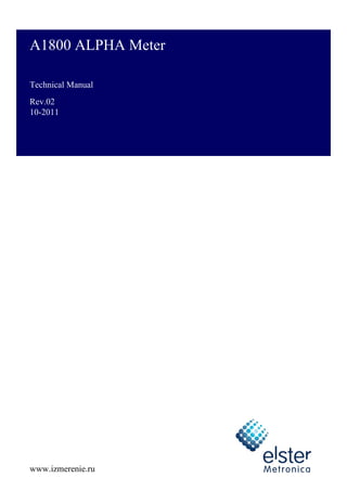
  • 9. Technical manual 1-1 Introduction 1 Introduction A1800 ALPHA meter The A1800 ALPHA meter family provides a platform that supports a variety of metering requirements. The A1800 ALPHA meter family is a totally electronic polyphase electricity meter and integral register for commercial and industrial applications. The meter is available in 3- and 4-wire configurations for 3 phases. See Figure 1-1 for an illustration of an A1800 ALPHA meter. Figure 1-1. A1800 ALPHA meter CT VT A V imp/kWh(kVARh) ELSTERSAM PLE 3x58/100...277/480V ,50Hz 1(10)A 0 .2 S 5,000 imp/kWh 5,000 imp/kVarh TYPE A1800 M O D E L T1 T2 T3 T4 T5 T6 T7 T8 EOI LC TC TST P - P + Q Q + - L L L 1 2 3 COM 0 1 2 Technical manual
  • 10. Technical manual 1-2 Introduction Standards Compliance IEC. The A1800 ALPHA meter meets or exceeds the following IEC standards for electricity metering. IEEE/ANSI. The A1800 ALPHA meter meets or exceeds the following IEEE/ANSI standards for electricity metering, and it is intended for use by commercial and industrial utility customers. DIN. The A1800 ALPHA meter meets or exceeds the following DIN standards for electricity metering. Table 1-1. IEC standards supported by the A1800 ALPHA meter Number Date Edition Title 62052-11 2003 1 General requirements, tests and test conditions. 62053-21 2003 1 Particular requirements-static meters for active energy (Classes 1.0 and 2.0) 62053-22 2003 1 Particular requirements-static meters for active energy (classes 0,2 S and 0,5 S) 62053-23 2003 1 Particular requirements-static meters for reactive energy (classes 2 and 3) 62053-31 1998 1 Particular requirements-pulse output devices for electromechanical and electronic meters (two wires only) 62053-61 1998 1 Particular requirements-power consumption and voltage requirements 62056-211 1 Complies with optical port requirements only. 2002 1 Electricity metering-data exchange for meter reading, tariff and load control-direct local data exchange 62052-21 2004 Electricity metering-tariff and load control- particular requirements for time switches Table 1-2. IEEE/ANSI standards supported by the A1800 ALPHA meter Number Date Title IEEE 1701/ ANSI C12.18 1996 Protocol Specification for ANSI Type 2 Optical Port IEEE 1377/ ANSI C12.19 1997 Utility Industry End Device Data Tables IEEE 1702/ ANSI C12.21 1999 Protocol Specification for Telephone Modem Communications Table 1-3. DIN standards supported by the A1800 ALPHA meter1 1 For meter width and location of lower mounting holes Number Date Title DIN 43857 Part 2 1978 Watthour meters in moulded insulation case without instrument transformers, up to 60 A rated maximum current; principal dimensions for polyphase meters.
  • 11. Technical manual 1-3 Introduction Benefits Reliability. The A1800 ALPHA meter, part of the ALPHA line of meters, uses the patented ALPHA meter technology for measurement and accurate calculation of energy quantities. With over 3 million ALPHA polyphase meters in operation throughout the world, the A1800 ALPHA continues the tradition of reliable electronic meters. The power supply in the meter operates from any available phase. A three-phase, four-wire A1800 ALPHA meter maintains operation if the neutral line and any one or two of the line voltages become disconnected. The meter can also operate using the auxiliary power supply, which can power the meter from an independent power source in the situation where main power is unavailable. The A1800 ALPHA meter can use its internal crystal oscillator or the power line frequency to maintain time and date functions. The crystal oscillator can be used when the power line frequency is known to be too unstable for accurate timekeeping. The A1800 ALPHA meter has been designed to function to provide long battery life. Because of the low current drain, the service life of the lithium battery can exceed the life of the meter. The A1800 ALPHA meter uses nonvolatile memory to store billing and other critical data. The data is preserved even if the power fails. Maintainability. The A1800 ALPHA meter is easy to maintain. Meter register functions and communication interfaces are fully integrated on a single, surface-mount technology circuit board. The meter firmware resides in flash memory, allowing the firmware to be upgraded in the field.
  • 12. Technical manual 1-4 Introduction ANSI standard communication open protocol. The A1800 ALPHA meter complies with the ANSI C12.18, C12.19, and C12.21 standards. These standards include communication protocols for a wide range of metering products. They are the basis for common industry data structures and a common protocol for transporting the data structures. Supporting the ANSI protocols makes it easier to add products to existing systems and provide an open standard for meter data communications. Adaptability. The A1800 ALPHA meter allows configuration for custom TOU rates (tariffs), offering a broad range of demand and TOU operations. Most common services and mounting configurations are supported, and functional upgrades are easily performed as new situations arise. The wide operating range allows installation at any of the common meter voltages. Additionally, the factory-configurable optical port accommodates IEC standard. The 16-segment character liquid crystal display (LCD) improves readability and provides flexibility for displaying meter information. As an added feature, the main meter circuit board provides selectable, independent, serial remote interfaces for RS-232 or RS-485 communication. Economy. The A1800 ALPHA meter saves both time and money. It can increase personnel productivity because of the following features: • no user calibration required (factory calibrated) • reduced testing times • fewer styles to learn and maintain • dual serial communications interfaces on the main meter circuit board • automated data retrieval • system service verification • on-site instrumentation displays • tamper restraint and quality monitoring (TRueQ™) tests • event logging Security. The A1800 ALPHA meter is tamper-resistant. Passwords may be specified that prevent unauthorized access to meter data. The standard TRueQ feature or the optional instrumentation profiling (or both) can be used to detect possible tampering of energy measurements. All A1800 ALPHA meters provide auditing capabilities that can be used to indicate potential meter tampering like terminal cover open detection and per phase outage recording. The A1800 ALPHA meter can be ordered with a partially-transparent terminal cover, making it easier to see obvious tampering. Accuracy. The A1800 ALPHA meter meets or exceeds requirements of IEC standards. The meter precisely measures demand and energy across a wide range of voltage and current despite variations in temperature and power factor. The low current sensor burden may also improve the accuracy of external current transformers when measuring light loads. Configuration IEC 62053-22 /GOST R 52323-2005/ IEC 62053-21 /GOST R 52322-2005/ IEC 62053-231 /GOST R 52425-2005// Class 0.2 S Class 0.5 S Class 1.0 Class 1.0 Class 2.0 direct connect1 1 Actual reactive energy accuracy is substantially better than required by the standard.     transformer-rated     
  • 13. Technical manual 1-5 Introduction Meter types Different meters within the A1800 ALPHA meter family have specific capabilities (see Table 1-4 and Figure 1-2). Note: Throughout this manual, the term A1800 ALPHA is used to describe any meter in the meter family. When necessary, a specific meter designation will be used to indicate that the description applies to only one meter in the meter family. Table 1-4. Meter designations of the A1800 ALPHA meter family Meter Market segment Class Standard features Optional features A1802 Interchange meter/ Large C&I 0.2S • 1 communications port (RS-232 or RS-485) • internal 128 KB (256KB) memory • auxiliary power supply • 4 relays • TRueQ • multitariffs • LCD backlight • Class 0.2 accuracy • transformer and line loss compensation (V) • 4-quadrant metering (A) • extended 1 MB memory (X) • load and instrumentation profiling (L) • add 1 communication port • Multi-protocol communications (Modbus, DNP 3.0) A1805 Large C&I/ Mid C&I 0.5S • 1 communications port (RS-232 or RS-485) • internal 128 KB (256KB) memory • auxiliary power supply • 4 relays • TRueQ • multitariffs • LCD backlight • Class 0.5 accuracy • transformer and line loss compensation (V) • 4-quadrant metering (A) • extended 1 MB memory (X) • instrumentation profiling (L) • load and instrumentation profiling (L) • add 1 communication port • Multi-protocol communications (Modbus, DNP 3.0) A18101 1 Contact Elster Metronica for availability. Small C&I/ Mid C&I 1.0 • 1 communications port (RS-232 or RS-485) • internal 128 KB (256KB) memory • auxiliary power supply • 4 relays • TRueQ • LCD backlight • multitariffs • transformer and line loss compensation (V) • 4-quadrant metering (A) • extended 1 MB memory (X) • instrumentation profiling (L) • load and instrumentation profiling (L) • add 1communication port A18202 2 Contact Elster Metronica for DC connected meter availability. Small C&I 0.5S • 1 communications port (RS-232 or RS-485) • internal 128 KB (256KB) memory • 4 relays • TRueQ • LCD backlight • Class 0.5 accuracy • extended 1 MB memory (X) • instrumentation profiling (L) • load profiling (L) • add 1communication port • multitariffs (T) A18213 3 Contact Elster Metronica for DC connected meter availability. Small C&I 1.0 • 1 communications port (RS-232 or RS-485) • internal 128 KB (256KB) memory • 4 relays • TRueQ • LCD backlight • extended 1 MB memory (X) • instrumentation profiling (L) • load profiling (L) • add 1communication port • multitariffs (T)
  • 14. Technical manual 1-6 Introduction Figure 1-2. A1800 ALPHA meter family application pyramid Residential Light C & I Mid C & I A1810 Large C & I A1805 A1802 A 1 8 0 0 A L P H A m e t e r f a m i l y Interchange metering A1810 A1820
  • 15. Technical manual 2-1 Product description 2 Product description Physical description The A1800 ALPHA meter is designed for indoor mounting. The cover assembly of the A1800 ALPHA meter exceeds the environmental requirements of IEC 62053-11. The case of the A1800 ALPHA meter provides an IP54 degree of protection for the meter. The physical components of the A1800 ALPHA meter consist of the following: • terminal cover • long terminal cover (see Figure 2-1) • short terminal cover (see Figure 2-2)1 • partially-transparent terminal cover • meter cover assembly • inner cover assembly • base electronic assembly Figure 2-1. Front view of the A1800 ALPHA meter 1 Contact Elster Metronica for availability. Technical manual
  • 16. Technical manual 2-2 Product description The terminal cover and meter cover assembly are manufactured using a UV-protected polycarbonate plastic. The terminal cover is available in either the long version or the short version. The meter cover assembly has a clear plastic window that allows the meter LCD and nameplates to be viewed. Figure 2-2. Front view of A1800 ALPHA meter with short terminal cover (transformer rated)1 The A1800 ALPHA meter can be sealed using any or all of the following methods: The four cover screws can be individually sealed (Figure 2-1). The two terminal cover screws limit access to the main terminals and auxiliary wiring connections only. Therefore, only the terminal cover seals must be broken to access these connections. The two meter cover screws are located on the lower front of the meter under the terminal cover. Sealing these screws seals the main enclosure and limits access to the metering circuit board and sensing elements. For maximum protection of the metering components, seal all four screw seals. 1 Contact Elster Metronica for availability. Seal location Purpose Meter cover screws (certification) Prevents access to the meter except for the main connections, relay connections, communication interface connections, and nameplate. Also can prevent reprogramming and recalibration of the meter. Terminal cover screws (utility) Prevents non-utility access to the main connections, relay connections, and utility information card RESET push button Prevents unauthorized manual demand resets
  • 17. Technical manual 2-3 Product description Figure 2-3. A1800 ALPHA meter with cover removed (transformer rated) Optical port. The A1800 ALPHA meter provides an optical port that can be ordered with IEC-compliant interface (see Figure 2-4). To use Elster meter support software to read or program the meter through the optical port, an optical probe is required. This probe connects from the serial port of the computer to the optical port on the meter. Figure 2-4. IEC-compliant optical port interface Elster Metronica recommends use of the AE-1 optical probe to reliably read the A1800 ALPHA meter. For information on ordering the AE-1 optical probe, visit www.izmerenie.ru or contact your local Elster Metronica representative. LCD. The A1800 ALPHA meter is equipped with a 16-segment character liquid crystal display. See “Indicators and controls” on page 3-1 for details. Nameplate. Elster Metronica installs the nameplate at the factory. See Appendix C, “Nameplate and style number information,” for details on the nameplate. IEC-compliant optical interface
  • 18. Technical manual 2-4 Product description Utility information card. The utility information card is removable (after the terminal cover has been removed) and allows the utility to enter meter site-specific information. See “Utility information card” on page C-2 for more information. Figure 2-5. Removing the utility information card Communications. The A1800 ALPHA meter (“-G” suffix) provides remote communications interfaces on the main meter circuit board for RS-232 or RS-485 serial communication. Physical outputs exist for both RS-232 and RS-485 interfaces; however, only one can be used at any given time. No configuration is necessary to switch between an RS-232 and RS-485 selection. Additionally, the A1800 ALPHA meter (“-S”, “-B” suffixs) provides a second, independent serial communication port that supports either RS-232 (see Figure 2-6) or RS-485 (see Figure 2-7). See Chapter 5, “Outputs,” for more information on the RS-232 or RS-485 ports. Figure 2-6. A1800 ALPHA meter (-S suffix) with RS-232 as second communication port Pulse output relay (optional) RS-232 connector RS-485 terminals RS-232 connector (optional)* *Present when optional second communication port is installed
  • 19. Technical manual 2-5 Product description Figure 2-7. A1800 ALPHA meter (-B suffix) with RS-485 as second communication port Battery. The terminal block has a battery well and connector for the optional TOU battery. Cover tamper detection switches. When either the terminal cover or the meter cover is opened, a detection switch is activated. (See Figure 2-8 for an illustration of the terminal cover detection switch; the meter cover detection switch is similar.) When either detection switch is activated, the TC indicator on the LCD turns on and remains on while the cover is removed. The date and time of the cover removal is logged in the event log. See “Event log” on page 2-14 for more information. Figure 2-8. Terminal cover detection switch Pulse output relay (optional) RS-232 connector RS-485 terminals RS-485 connector (optional)* *Present when optional second communication port is installed Cover closed Cover opened
  • 20. Technical manual 2-6 Product description Terminal configurations. The A1800 ALPHA meter supports the following terminal configurations: • 10 A transformer-rated (sequential) • 100 A direct connect-rated (sequential) System architecture The A1800 ALPHA meter main circuit board contains all the electronics that make up the meter registers and communication interfaces. See for the meter circuit board block diagram. The circuit board as shown in contains the following: • meter engine • microcontroller • EEPROM • resistive dividers for the 3 phase voltages • load resistors for the 3 current sensors • power supply • high frequency crystal oscillator • 32 kHz low power timekeeping crystal oscillator • optical port components • liquid crystal display (LCD) interface • RS-232 and RS-485 communication interfaces • option board interface • pulse outputs Figure 2-9. Meter block diagram Pulse outputs Wide input power supply 5 V linear power supply Non volatile supply Precision reference Low power crystal Resistive divider Resistive divider Resistive divider Option connector Optical port Remote port 1/2 Battery LCD Microcontroller EEPROM Crystal Meter engine Clock varh Rec varh Del Wh Rec Wh Del C B A 2x Line Freq Power Fail Phase A voltage Phase B voltage Phase C voltage Current sensor Phase A current Phase B current Phase C current Current sensor Current sensor
  • 21. Technical manual 2-7 Product description General theory of operation The A1800 ALPHA meter’s engine receives analog inputs of voltages and current to calculate the desired metered quantities. The meter engine samples the input voltages and current 66 to 88 times per cycle. The actual sampling frequency is based on whether 50 Hz or 60 Hz1 power systems are being measured. Using these input signals, the meter engine calculates root mean square (rms) values of voltage and current, and the meter engine uses the sampled signals to compute Wh, VAh, and VArh quantities for each phase. These individual phase quantities are summed, and the totals are transmitted to the microprocessor. The microprocessor processes and stores the data into memory according to the user-specified program. Once stored, data values are available to be displayed and communicated as required by the utility or other meter user. The very high sampling rate inherent in the meter engine and the additional over sampling techniques used in the A1800 ALPHA meter results in very high accuracy regardless of harmonic content, phase angle, or point on the load curve. The meter engine accumulates and recalculates all quantities after every line cycle. This provides the ability to include the effect of harmonics up to and beyond the 33rd harmonic. Individual harmonics up to and including the 15th harmonic are displayable items and are included in distortion measurements. Further advanced electronic techniques are used to provide extreme stability of accuracy over time and over an exceptionally wide range of operating and load conditions. The A1800 ALPHA meter can accommodate various tariff structures. The meter also supports a variety of communication options that allow the meter to be read remotely or manually. In addition, relays may be used for pulse outputs of user-selected quantities or for signaling the start of a tariff period. Power supply Main power supply. Power is supplied to the A1800 ALPHA meter using a wide voltage range power supply that accepts voltages from 49 V to 528 V AC. At least two lines must be present to power the meter circuitry. The output from the power supply is then fed to a low voltage linear regulator to attain the low level voltage. Auxiliary power supply. The A1800 ALPHA meter may be ordered with an auxiliary power supply. The auxiliary power supply allows the A1800 ALPHA meter to be powered by a separate AC or DC power source, such as substation’s independent power lines. Should the main power supply be unavailable, the meter will be fully operational provided the independent power is still available. The A1800 ALPHA meter can also be connected to both the main power source and auxiliary power source, providing uninterrupted power in the event that the main power becomes unavailable. The auxiliary power supply accepts the following voltages: • For independent AC power, from 57 V rms to 240 V rms (115V nominal) • For independent DC power, from 80 V to 340 V Note: When using independent DC power, the A1800 ALPHA meter’s auxiliary power supply is polarity independent. The meter will operate properly without regard to which wire is positive and which wire is negative. The output from the independent power supply is then fed to a low voltage linear regulator to attain the low level voltage. Current and voltage sensing Power line currents and voltages are sensed using specialized current sensors and resistive dividers, respectively. Multiplication and other calculations are performed using a custom integrated circuit (called the meter engine). 1 Contact Elster Metronica for availability.
  • 22. Technical manual 2-8 Product description The meter receives each phase current through a precision-wound current sensor that reduces the line current proportionally. The meter engine samples the individual phase currents to provide accurate current measurement. The meter receives each phase voltage through resistive dividers. This ensures that a linear low level voltage is maintained. It also serves to minimize phase shift over a wide dynamic range. The meter engine samples the scaled inputs provided by the resistive dividers to provide accurate voltage measurements. Meter engine Multiplication and other calculations are performed using a custom integrated circuit, called the meter engine. The meter engine contains the digital signal processor (DSP) with built-in analog-to-digital (A/D) converters capable of sampling each current and voltage input. The A/D converters measure the voltage and current inputs for a given phase. The DSP multiplies the signals appropriately, using the factory-programmed calibration constants. Microcontroller The microcontroller performs many different functions, for example: • communicates with the DSP and EEPROM • provides for serial communication over the optical port • provides for serial communication over the remote ports • generates optical output pulses • controls the LCD • controls any option boards The microcontroller and the meter engine communicate with each other constantly to process voltage and current inputs. When the microcontroller detects a power failure, it initiates the shutdown and stores billing and status information in EEPROM. EEPROM The A1800 ALPHA meter uses electrically erasable programmable read only memory (EEPROM) for nonvolatile storage of manufacturing data, meter configuration data, and energy measurement values. The A1800 ALPHA meter is provided with either 128 KB or 256 KB of main board memory. See “Style number information” on page C-3 for information regarding how to identify the amount of main board memory on your meter. The EEPROM provides storage of all information needed to ensure the integrity of the demand or energy calculations, including the following: • configuration data • billing data • all TOU data • log and profiling data • meter status • constants • energy usage • maximum demand • cumulative demand
  • 23. Technical manual 2-9 Product description Billing data Metered energy and demand quantities All A1800 ALPHA meters are capable of measuring delivered and received kWh energy and kW demand. The A1800 ALPHA meters can also measure reactive and apparent energy and demand. The meter engine samples the voltage and current inputs and sends these measurements to the microcontroller. In the meter engine, each pulse is equal to one Ke defined as one of the following: • secondary rated Wh per pulse • secondary rated varh per pulse • secondary rated VAh per pulse The following list shows the available metered quantities for the A1800 ALPHA meter. Basic metered quantities (indicated by * in Table 2-1) can be selected as a source for relay outputs. The remaining metered quantities are calculated from 2 or more basic metered quantities. Average power factor The A1800 ALPHA meter can calculate the average power factor (AvgPF) using kWh and kvarh values since the last demand reset. The meter can store up to two average power calculations, which can be configured in Elster’s meter support software. Average power factor is calculated every second. Upon a demand reset, the values used in this calculation are set to zero and the AvgPF will be set to 1.000. Demand calculations Demand is the average value of power over a specified time interval. The A1800 ALPHA meter supports three different methods for demand calculation: • rolling interval • block interval • thermal time constant An interval is the time over which demand is calculated. The length of a demand interval is programmable using Elster meter support software, but the value must be evenly divisible into 60 minutes. Common demand interval lengths are 15 or 30 minutes. Table 2-1. Metered energy and demand quantities • kVAh delivered (Q1 + Q4) • kVAh Q1 • kVAh Q2 • kVAh Q3 • kVAh Q4 • kVAh received (Q2 + Q3) • kVAh sum (delivered + received) • kvarh (Q1 - Q4) • kvarh (Q1 + Q4)* • kvarh (Q2 - Q3) • kvarh (Q2 + Q3)* • kvarh (Q3 - Q2) • kvarh delivered (Q1 + Q2)* • kvarh net • kvarh Q1* • kvarh Q2* • kvarh Q3* • kvarh Q4* • kvarh received (Q3 + Q4)* • kvarh sum (delivered + received)* • kWh delivered* • kWh net • kWh received* • kWh sum* 2 2 kWh h var k kWh AvgPF  
  • 24. Technical manual 2-10 Product description Rolling interval. Rolling demand interval is defined by two parameters: • the demand interval length - specified in minutes and may be any value that is evenly divisible into 60 • subinterval length - also specified in minutes and may be any value that is evenly divisible into the interval length Both of these values are configurable by Elster meter support software. The demand is calculated at the end of each subinterval, resulting in overlapping demand intervals (or a “rolling” demand). For example, the A1800 ALPHA meter can be configured for a 15-minute demand interval length and a 5-minute subinterval length. In this case, the demand is calculated every 5 minutes based on the 3 previous subintervals (see Figure 2-10). Figure 2-10. Rolling demand intervals The rolling interval calculates demand by using the following equation: For example, if the demand interval is 15 minutes and the total accumulated energy is 50 kWh, then the demand is 200 kW. Block interval. Block demand interval is a special case of rolling interval demand in which the subinterval is the same size as the interval (see Figure 2-11). Figure 2-11. Block demand intervals sub- interval sub- interval sub- interval sub- interval sub- interval 5 0 10 15 20 25 Time (minutes) 15-minute interval 15-minute interval 15-minute interval hours t energy d accumulate total D  kW 200 h 0.25 kWh 50 D   sub- interval sub- interval sub- interval sub- interval Time (minutes) 15 30 45 60 0 interval interval interval interval
  • 25. Technical manual 2-11 Product description Thermal time constant. The A1800 ALPHA meter can perform thermal demand emulation. The meter calculates demand based on a logarithmic scale that accurately emulates thermal demand meters. The thermal demand time constants vary depending upon the operational mode of the meter. • Normal mode time constant is 15 minutes. • Test mode time constant is 1 minute. See “Operating modes” on page 3-7 for more information. Maximum demand Maximum demand (also referred to as indicating or peak demand) is the highest demand value that occurs in a billing period. The demand for each demand interval is calculated and compared to an earlier maximum demand value. If the new interval demand exceeds the previous maximum demand, then the new demand is stored as the maximum demand (see Figure 2-12). When a demand reset occurs, the maximum demand is reset to zero. The demand for the first full interval after a demand reset becomes the maximum demand. Figure 2-12. Maximum demand In addition to maximum demand, the A1800 ALPHA meter also stores either the cumulative or continuous cumulative demand. A1800 ALPHA meters can be programmed to trigger the recording of a coincident demand or power factor (see “Coincident demand or power factor” on page 2-12). Cumulative maximum demand Using cumulative maximum demand, a demand reset adds the current maximum demand value to the cumulative maximum demand. This feature is used to calculate the previous maximum demand when the demand may have had an unauthorized reset. Since the cumulative demand is not reset to zero, unauthorized demand resets do not cause a loss of the maximum demand data. To determine the maximum demand for a billing period after a demand reset, subtract the previous cumulative demand from the current cumulative demand. Continuous cumulative maximum demand Continuous cumulative maximum demand works similarly to cumulative maximum demand. Continuous cumulative demand, however, is always equal to the sum of the previous billing period continuous cumulative demand and the current maximum demand. This feature is used to calculate the previous maximum demand when the demand may have had an unauthorized reset. Interval 6 demand (9.2 kW) Interval 8 demand (9.5 kW) Interval 7 demand (9.9 kW) New maximum demand (9.9 kW) Earlier maximum demand (9.9 kW) Earlier maximum demand (9.7 kW)
  • 26. Technical manual 2-12 Product description Coincident demand or power factor The number of coincident values that may be captured by the A1800 ALPHA meter depends on whether or not the 4-quadrant metering (“-A” suffix) option is present. • A1800 ALPHA meters without 4-quadrant metering record 2 coincident values. • A1800 ALPHA meters with 4-quadrant metering record up to 4 coincident values. Coincident demand refers to a demand value that occurs at the same time as another demand reaches its peak value. For example, an electric utility may want to record the kvar demand at the time of a maximum kW demand. This requires that kvar demand be stored and reported during the same interval as the maximum kW demand. Similarly, coincident power factor refers to a power factor that occurs at the same time as a demand value reaches its peak value. For example, an electric utility may want to record the power factor at the time of a maximum kvar demand. This requires the power factor be stored and reported during the same interval as the maximum kvar demand. Demand forgiveness Demand forgiveness is the time during which demand is not calculated or stored after a qualified power outage. Demand forgiveness has two programmable settings: • outage time: the number of minutes a power outage must last to qualify for demand forgiveness (0 to 15 minutes) • time: the number of minutes that demand is not calculated or stored (0 to 255 minutes) following a qualified power outage; zero disables demand forgiveness Primary and secondary metering The A1800 ALPHA meter can be programmed for either primary or secondary metering. When configured for primary metering, the A1800 ALPHA meter internally converts the measured energy, demand and instrumentation quantities to primary units using the voltage transformer ratio and the current transformer ratio. These ratios are programmed using Elster meter support software. The metered quantities reflect energy, demand and instrumentation on the primary side of the instrument transformers. When configured for secondary metering, the A1800 ALPHA meter does not use the voltage transformer ratio or the current transformer ratio to adjust the metered quantities. The metered quantities reflect the energy, demand and instrumentation on the secondary side of the instrument transformers even if the voltage and current ratios are programmed into the meter. TOU data All A1800 ALPHA meters store the total (single-rate) data for energy and demand. TOU meters can store the total data and the data for up to 4 rates. TOU rates can be based on any combination of day (up to 4 day types), time (up to 132 switch times), or season (up to 12 seasons). The switch points for energy and demand may be configured independently of each other. All selected metered quantities are stored according to the TOU rate. The meter stores the energy, demand, and average power factor for each rate. 2 2 kWh kvarh kWh PF Coincident  
  • 27. Technical manual 2-13 Product description Power failure data The A1800 ALPHA meter monitors and records the total power failure data. The following information is recorded: • cumulative number of minutes of all power failures • start date and time of the most recent power failure • end date and time of the most recent power failure These values can be programmed to display on the LCD. See Appendix B, “Display table,” for more information about displayable items. See “Event log” on page 2-14 for information on loss of phase voltage. Logs and data sets All A1800 ALPHA meters are equipped with EEPROM. As shown in Figure 2-13, a small portion of this main board memory is permanently reserved (called “reserved memory”) by the meter to store the main billing and configuration information. The remainder of the memory (called “shared memory”) is used to store the following logs and data sets: • event log • history log • self reads • load profiling • instrumentation profiling • TRueQ log • voltage sag log All of the logs and data sets share the meter’s memory. Using Elster meter support software, the sizes of each log or data set can be configured to allow more room for a different log or data set. For example, self reads can be configured to store less data so that the load profiling can store more data. Figure 2-13. Allocation of meter memory Reserved memory** Main circuit board memory (128 KB or 256 KB) IP,* LP* Billing data, Configuration data, Manufacturing info, etc. Event, History, TRueQ, Voltage sag Self read, LP,* IP* Extended memory option board (1 MB) Shared memory *Extended memory used only when requested number of days exceeds the capacity of main board memory. If meter support software is set to maximize data storage, then the extended memory option board would always be used for LP and IP data storage. Notes **Size of reserved memory is fixed and may vary with each firmware release.
  • 28. Technical manual 2-14 Product description In most cases, the 128 KB or 256 KB option is sufficient to meet data logging and profiling requirements. In some cases (for example, if extensive instrumentation profiling is desired), more memory may be required. When the data storage cannot be met with the 256 KB main memory option, extended memory can be used to add shared memory to the A1800 ALPHA meter. Event log All A1800 ALPHA meters have an event log. The A1800 ALPHA meter stores the date and time that events occur. Elster meter support software is used to define and program the number of event log entries that the meter will record. Events that can be included in the event log are as follows: • power fail start and stop (2 event log entries) • date and time change information (2 event log entries) • date and time of demand resets (1 event log entry) • date and time of event log reset (1 event log entry) • date and time of test mode activity (2 event log entries) • start and stop time when the current TOU rate is overridden by the alternate TOU rate schedule (2 event log entries) • start and stop time of per phase outage (2 event log entries) • date and time of terminal cover removal (1 event log entry) • date and time of main cover removal (1 event log entry) Note: The meter will detect and log the removal of either the terminal cover or main cover even when the meter is not powered (provided the TOU battery is functioning). After the maximum number of entries has been stored, the meter will begin overwriting the oldest entries. The event log can be disabled through Elster meter support software. History log All A1800 ALPHA meters have a history log that stores table information and procedure ID for configuration-altering writes to the meter. The A1800 ALPHA meter records a sequential listing of records, along with the date and time. The meter records this information as an audit trail, maintaining a history of programming changes made to the meter. After the maximum number of entries has been stored, the meter will begin overwriting the oldest entries. The history log can be disabled through Elster meter support software. Self reads All A1800 ALPHA meters can support self reads. A self read captures the current period billing data and stores it in memory. The A1800 ALPHA meter can store up to 35 self reads can be stored depending on memory requirements for logs, data, etc. This data can be retrieved later for analysis or billing. If the meter has recorded the maximum number of self reads, the next self read will overwrite the oldest copy. Self reads are events that can be triggered by any of the following: • scheduled calendar events • every demand reset • communication procedure Self reads are different from previous billing data copies. The previous billing data copy stores only one copy of billing data at a time and only when a demand reset occurs. See “Demand reset data area” on page 3-10 for more information.
  • 29. Technical manual 2-15 Product description Load profiling For meters with load profiling capabilities (designated with an “-L” suffix), the A1800 ALPHA meter is capable of recording 8 channels of information. Load profiling has its own, separate interval length that is configured independently from the demand interval length. The length of the load profiling interval must adhere to the following rules: • the length must be between 1 and 60 minutes • the time must be evenly divisible into an 60 minutes Table 2-3 show the number of days of load profiling available. These values are estimates and may vary depending on the firmware used in the meter. Data in Table 2-3 are based on the following settings: • load profiling at 15-minute intervals • no instrumentation profiling • the meter is programmed for 6 metered quantities, 2 average power factors, and 4 coincident values The first number shows the number of days of load profiling, assuming all other logs and self reads record the maximum number of entries. The second number shows the number of days of load profiling, assuming all other logs and self reads record the minimum number of entries. Note: The actual number of days stores varies based on meter firmware release and other options programmed using Elster meter support software. See the documentation for the meter support software for more information regarding memory allocation. Load profiling pulse divisor. A pulse divisor is used to scale down the number of pulses recorded in each load profiling interval. This allows recording of data that may exceed the maximum number of pulses that can be stored in each load profiling interval (each interval can store 32,767 pulses before overflowing). The range for the value of the load profiling pulse divisor is 1 (default) to 255. Table 2-2. Load profiling sources • kVAh delivered (Q1 + Q4) • kVAh Q1 • kVAh Q2 • kVAh Q3 • kVAh Q4 • kVAh received (Q2 + Q3) • kVAh sum • kvarh (Q1 - Q4) • kvarh (Q1 + Q4) • kvarh (Q2 - Q3) • kvarh (Q2 + Q3) • kvarh (Q3 - Q2) • kvarh delivered (Q1 + Q2) • kvarh net • kvarh Q1 • kvarh Q2 • kvarh Q3 • kvarh Q4 • kvarh received (Q3 + Q4) • kvarh sum • kWh delivered • kWh net • kWh received • kWh sum Table 2-3. Estimated days of load profiling storage per number of channels Days of storage (max./ min.) Number of channels 1 2 3 4 5 6 7 8 128 KB 199/320 106/171 81/130 60/96 51/81 41/66 37/59 32/51 256 KB 594/714 317/381 242/291 178/214 151/182 124/149 110/133 95/114 1 MB 3177 1696 1294 954 812 664 592 509
  • 30. Technical manual 2-16 Product description Instrumentation profiling In meters with instrumentation profiling, the meter has two sets of instrumentation profiling. Each set can record up to 16 channels from the sources listed in Table 2-4. Also, instrumentation profiling can use the sources listed in Table 2-2 for more extensive load profiling. Table 2-4. Instrumentation profiling sources • frequency • per phase current • per phase voltage • per phase watts • per phase VA • per phase voltage angle with respect to line 1 voltage • per phase fundamental (1st harmonic) current magnitude • per phase fundamental (1st harmonic) voltage magnitude • per phase 2nd harmonic current magnitude • per phase 2nd harmonic voltage magnitude • per phase voltage % total harmonic distortion (THD) • per phase current % THD • per phase harmonic current (sum of 2nd through 15th ) • per phase current angle with respect to line 1 voltage • per phase vars (vectorial) • per phase 2nd harmonic voltage % • per phase total demand distortion (TDD) • per phase PF • per phase PF angle • system watts • system VA (arithmetic) • system PF (arithmetic) • system PF angle (arithmetic) • system vars (vectorial) • system VA (vectorial) • system var (arithmetic) • system PF (vectorial) • system PF angle (vectorial)
  • 31. Technical manual 2-17 Product description Each channel can be configured to record the instrumentation profiling using any one of following four algorithms (see Table 2-5): Each set of instrumentation profiling has its own, separate interval length that is configured independently from the demand interval length. The length of the instrumentation profiling interval must adhere to the following rules: • the length must be between 1 and 60 minutes • the time must be evenly divisible into an 60 minutes TRueQ Log The A1800 ALPHA meter has a TRueQ log that records TRueQ test failures. Elster meter support software is used to define and program the number of TRueQ log entries that the meter will record. Elster meter support software is also used to define which tests can record failures in the TRueQ log. The A1800 ALPHA meter can record the following data associated with the TRueQ test: • the date and time when the TRueQ monitor first detects a qualified failure and the identifier of the TRueQ test (1 TRueQ log entry) • the date and time when the TRueQ monitor no longer detects a failure and the identifier of the TRueQ test (1 TRueQ log entry) Note: See “TRueQ event counters and timers” on page 4-15 for information on qualification time For each TRueQ log entry, the meter also records an instrumentation measurement related to the TRueQ test. When the maximum number of entries has been stored, the meter will begin overwriting the oldest entries. See “TRueQ monitoring” on page 4-12 for more information. Voltage sag log The meter has a voltage sag log. The A1800 ALPHA meter records the date, time, and phases of any detected voltage sag. The log records a maximum of 1 entry per second. When the maximum number of entries has been stored, the meter will begin overwriting the oldest entries. See “Voltage sags” on page 4-13 for more information. User-defined tables User defined tables offer specific data retrieval options for A1800 ALPHA meters. User defined table configuration may be requested at the time of purchase, and the specific configuration may be programmed at the factory. An AMR system can then be configured to retrieve the user defined table information from the meter instead of individual table reads. This reduces the total communications time. Table 2-5. Instrumentation profiling recording algorithms Item Description Minimum The meter samples the selected quantity over the instrumentation interval. The minimum value of all the samples is recorded. Maximum The meter samples the selected quantity over the instrumentation interval. The maximum value of all the samples is recorded. Average The meter samples the selected quantity over the instrumentation interval. The average value of all the samples is recorded. End The meter samples the selected quantity over the instrumentation interval. The last value of all the samples is recorded.
  • 32. Technical manual 2-18 Product description Physical dimensions and mass The approximate dimensions of the meter correspond to DIN 43-857 part 2 (excluding the meter hanger). See the following figures for illustrations of the meter and its dimensions. Figure 2-14. A1800 ALPHA meter, standard terminal cover Figure 2-15. A1800 ALPHA meter, short terminal cover1 1 Contact Elster Metronica for availability. 204 22 224* 150 170 307 89 5 *This represents hanger in center position. Approximate dimensions in millimeters 213* 224* 22* 150 170 89 240 5 *This represents hanger in center position Approximate dimensions in millimeters
  • 33. Technical manual 2-19 Product description Figure 2-16. A1800 ALPHA meter, back of meter Figure 2-17. A1800 ALPHA meter, bottom view (direct connect1 and transformer rated) 1 Contact Elster Metronica for availability. Table 2-6. Approximate mass Elements Direct connect Transformer rated 2-element 1.6 kilograms 1.3 kilograms 3-element 1.7 kilograms 1.3 kilograms Approximate dimensions in millimeters. 202 150 170 6.2 5.4 170 Ø 10 Approximate dimensions in millimeters. Direct connect meter Transformer rated meter
  • 34. Technical manual 2-20 Product description
  • 35. Technical manual 3-1 Operating instructions 3 Operating instructions Indicators and controls LCD The liquid crystal display (LCD) is used to display meter data and status information. Figure 3-1 shows the dimensions of the LCD. Figure 3-1. LCD dimensions As shown in Figure 3-2, the LCD is divided into different display regions. Figure 3-2. LCD regions P - P + Q Q + - 7 Approximate dimensions in millimeters 9.5 27 32 77 85 5 2 3.5 1.4 Viewing area P - P + Q Q + - L L L 1 2 3 COM 0 1 2 Error/warning indicator Energy direction indicator Display quantity Tariff indicators 1 to 8 (left to right) EOI indicator LC indicator Cover removed indicator Test mode indicator Power/energy units identifier Comm. port indicator Alternate mode indicator Quantity identifier Low battery indicator Phase indicators (3) Technical manual
  • 36. Technical manual 3-2 Operating instructions All A1800 ALPHA meters have a backlight option for the LCD. The LCD can be illuminated by pressing one of the push buttons, making it easier to read the LCD in no-light or low-light conditions. The backlight option must be specified at the time of ordering. See “Using the backlight” on page 3-6 for more information. Quantity identifier. This 7-digit region identifies the displayed quantity as defined and programmed with Elster meter support software. An identifier can be assigned to most display quantities in the display sequence. See Appendix B, “Display table,” for more information. Display quantity. This 8-digit display on the LCD shows either metered quantities or other displayable information, depending upon how the A1800 ALPHA meter has been programmed. The displayable digits are definable using Elster meter support software for both energy and demand readings. From 3 to 8 digits with up to 4 decimal places can be used. These digits are also used to report error codes for the following error conditions: • operational errors (E1, E2, or E3) • system instrumentation and service test errors (SE) • warnings (W1 or W2) • communication codes (COM 0, COM 1, COM 2) For instrumentation values and tests, numeric values may be replaced by or mixed with alphabetic characters to better define the value. See Appendix B, “Display table,” for more information. Phase indicators. Each phase indicator (L1, L2, and L3) corresponds to a line voltage (Line 1, Line 2, and Line 3, respectively) present on the A1800 ALPHA meter connections. The state of the indicators correspond to the following: • If the indicators are on, then all expected line voltages are present. • If an indicator is blinking, then that expected line voltage is either missing or below the defined threshold for voltage sag detection. • If an indicator is off, the line is not expected for the configured meter type. See “Voltage sags”for more details on momentary voltage sag detection and the phase indicators. Energy direction indicators. The energy direction indicators display the quadrant and direction of the last Wh (active) and varh (reactive) energy flow. Positive energy flow is energy delivered to the consumer load, while reverse energy flow is energy received from the consumer load. Figure 3-3 shows the meaning of each energy direction indicator. The energy direction indicators turn on to display energy flow direction when any of the meter phases are measuring energy flow (that is, when one of the line currents is above the meter starting threshold). Figure 3-3. Energy direction indicators Positive reactive energy Reverse reactive energy Positive active energy Reverse active energy
  • 37. Technical manual 3-3 Operating instructions On meters with the Always Positive option, the +P indicator is on continuously whenever kWh flow of any direction is detected. The –P indicator is inoperative for this meter configuration (see “Always Positive” on page 2-13 for more information). Power/energy units identifier. The power/energy units identifier is used to indicate the unit of measurement for the quantity displayed on the meter’s LCD. In some cases, it may not be possible to represent the displayed quantity using the power/energy units identifier. If this is the case, then the power/energy units identifier will not be used. Instead, the quantity will be identified either using the quantity identifier or appending the unit to the display quantity. Alternate display indicator. This indicator (*) displays when the A1800 ALPHA meter is operating in alternate mode. This indicator also displays during the all segment test of the LCD. See “Operating modes” on page 3-7 for more information on the different operating modes. Error indicator. The error indicator flashes when any error condition is present or remains on if a warning condition is present. When the error indicator is on, the LCD will also display the appropriate error or warning code. See “System service error codes” on page 4-10 and “Codes and warnings” on page 6-2 for details. Note: This indicator also turns on during the LCD all-segments test. Low battery indicator. The low battery indicator is turned on when the TOU battery voltage is low or when the TOU battery is missing. Additionally, the low battery warning display item (if included in the display list) also is displayed. Note: This indicator also turns on during the LCD all-segments test. Active COM port indicator. The active COM port indicator indicates that a communication session is in progress and which COM port is being used. See “Communication codes” on page 6-8 for additional details. Display indicators. The 12 display indicators () are used to more precisely identify the information displayed on the meter’s LCD. Note: These identifiers may be shown individually or in combination to describe a particular displayed quantity. Note: The manufacturer’s nameplate details the meaning of the display indicators. See Appendix C, “Nameplate and style number information.” Tariff indicators. The tariff indicators (T1, T2, T3, and T4) indicate the current tariff. If the displayed quantity is a TOU item (for example, tariff 1 total kWh), the corresponding indicator (T1) turns on. If the quantity’s tariff is active at the time, the tariff indicator flashes. Note: The active tariff indicators also turns on during the LCD all-segments test. EOI indicator. The end-of-interval (EOI) indicator is used to verify the timing of the demand interval. Ten seconds before the end of the demand interval, the EOI indicator will be turned on and remain on until the end of the interval. Table 3-1. Port codes Code Port COM 0 Optical port COM 1 Remote port 1 COM 2 Remote port 2
  • 38. Technical manual 3-4 Operating instructions For rolling demand, the EOI indicator turns on for 10 seconds before the end of each subinterval. Transformer and line loss compensation indicator. The loss compensation (LC) indicator indicates the meter is currently compensating for transformer and line loss. Cover tamper indicator. The cover tamper (TC) indicator indicates that either the terminal cover or the meter cover is removed. This may indicate that tampering has occurred on the meter. The TC indicator turns off when all the covers are in place. See “Cover tamper detection switches” on page 2-5 for additional information. Test mode indicator. The test (TST) mode indicator indicates that the meter is currently operating in test mode. See “Test mode” on page 3-8 for details. Push buttons The following push buttons are located on the front of the A1800 ALPHA meter: • RESET (sealable) • * (ALT) If sealed, the RESET button is only accessible after breaking the seal; the button is always accessible. Figure 3-4. A1800 ALPHA meter push buttons RESET button. To activate the RESET button, it may be necessary to break the seal that locks the RESET button in the inactive position. After the seal is broken, rotate the push button 90 ° in either direction and press the push button (see Figure 3-5). Pressing the RESET button performs a demand reset (see “Demand reset” on page 3-9 for a description on what happens during a demand reset). The RESET button performs differently depending on the A1800 ALPHA operating mode, as shown in Table 3-2. * (ALT) button RESET button (sealable)
  • 39. Technical manual 3-5 Operating instructions To seal the RESET button, rotate the RESET button 90 ° back to the inactive position and apply the seal. Figure 3-5. RESET button positions Using to lock service. Pressing the RESET button will accept and lock the detected service when the service test lock mode has been set to manual and the system service voltage test has just been performed by the A1800 ALPHA meter. See “Manual lock” on page 4-6 for more details. Using the RESET button to lock the service will not perform a demand reset unless it is pressed a second time. * button. Pressing the button normally initiates the alternate mode (see “Operating modes” on page 3-7 for more information about the A1800 ALPHA operating modes). The * button performs differently depending on the operating mode, as shown in Table 3-3. Note: All the A1800 ALPHA meter have the backlight display option, therefore the * button can be used to illuminate the display. See “Using the backlight” on page 3-6 for more information. Table 3-2. RESET button behavior Mode Description Normal Performs a demand reset Alternate Returns to normal mode and performs a demand reset Test Resets test value and remains in test mode Inactive position RESET button cannot be pressed Active position RESET button can be pressed
  • 40. Technical manual 3-6 Operating instructions Using the backlight. All the A1800 ALPHA meter have the backlight for the LCD. Once the backlight is turned on, the LCD will be illuminated for two minutes. To illuminate the LCD, use the following process (see Figure 3-6): 1. Press either the * button or the RESET button. The backlight turns on for the specified illumination time. 2. While the LCD is illuminated, the push buttons will operate as follows: • The RESET button operates as specified in Table 3-2. • The * button operates as specified in Table 3-3. 3. The backlight will turn off at the end of the illumination time. Pressing either the * button or the RESET button restarts the process, beginning with step 1. The A1800 ALPHA meter can be ordered with the backlight always turned on. With this option, the LCD backlight will always be illuminated, and the RESET and * buttons will operate as specified in Table 3-2 and Table 3-3, respectively. Table 3-3. * button function in different operating modes Mode Press method Description Normal Less than 1 second Enters alternate mode, LCD displays one cycle of the alternate display list, and returns to normal mode. Alternate Continuous Scrolls quickly through the alternate display list while pressed; locks LCD on a display quantity when released. Press and release If the LCD is locked on a display quantity, each press steps to the next quantity in the alternate display list. Test Continuous Scrolls quickly through the test mode display list while pressed; locks LCD on a display quantity when released. Press and release If the LCD is locked on a display quantity, each press steps to the next quantity in the test display list.
  • 41. Technical manual 3-7 Operating instructions Figure 3-6. Using the backlight on the A1800 ALPHA meter LCD (default operating mode) Operating modes The A1800 ALPHA meter operates in one of the following modes: • normal mode • alternate mode • test mode As part of its function, the meter performs self tests to make sure it is operating normally. The self test ensures that the A1800 ALPHA meter is functioning properly and that its displayed quantities are accurate. If the self test indicates an error, the LCD displays the error indicator. In addition, the meter can be programmed to “lock” the error code on the display. The meter attempts to function normally, however, the meter data may be suspect. See “Meter self test” on page 6-1 for more information on self tests and errors. Normal mode Normal mode is the default operation mode for the A1800 ALPHA meter. It is generally used to display billing data on the LCD. The meter is fully operational in this mode, and it will process and store data while the LCD scrolls through the normal display list quantities. The LCD test will always appear immediately after power is connected to the A1800 ALPHA meter or after a power restoration from an outage. Backlight off Any button is pressed Backlight on Button pressed while LCD lit? Perform demand reset Enter alternate mode Has time expired? Yes, * Yes, RESET Yes No No
  • 42. Technical manual 3-8 Operating instructions Typically, the normal mode display cycle begins with an LCD test which turns on all of the display segments. This is recommended because it provides a quick way to determine if the LCD is functioning properly. The LCD test can be disabled using Elster meter support software. The normal display cycle will scroll through all programmed display quantities before beginning the cycle again. While in normal mode, the LEDs transmit pulses proportional to metered energy. See “LED pulse outputs” on page 5-6 for details on the LEDs. Alternate mode Alternate mode can be programmed with Elster meter support software to display a second set of quantities on the LCD. Alternate mode is most often used for displaying non-billing data, but it can be programmed to display any of the available quantities. This mode is activated in one of the following ways: • pressing the * button on the A1800 ALPHA meter • after power up for one cycle of the alternate display list Note: This feature can be disabled using Elster’s meter support software. The meter is fully operational while in alternate mode. While in alternate mode, the alternate display indicator is turned on. Additionally, the LEDs transmit pulses (see “LED pulse outputs” on page 5-6). There are several different ways to exit alternate mode. Whenever exiting the alternate mode, the meter returns to normal mode. Test mode The A1800 ALPHA meter enters test mode by a command through the optical port. While in test mode, the test mode indicator (TST) will flash on the meter’s LCD. Test mode displays test readings without affecting the present energy usage and billing data values in the A1800 ALPHA meter. Shorter demand intervals may be used in test mode to reduce demand test time and will not interfere with billing data. When normal mode is resumed, readings taken during test mode will be discarded and present energy usage and billing data values will be restored. The status of the meter (including billing data, profiling data, errors, and warnings) before the meter entered test mode is restored. While in test mode, the optical port transmits test pulses proportional to metered energy (see “LED pulse outputs” on page 5-6). Table 3-4. Exiting alternate mode Method Description Wait for the end of the alternate display list If the meter is scrolling through the alternate display list automatically, the meter exits alternate mode after the last item is displayed. Press the RESET button Exits alternate mode and performs a demand reset. Wait for the timeout If the LCD remains on a quantity, the meter exits alternate mode after 2 minutes of inactivity. If the LCD remains on a pulse line cumulative counter, the meter will exit the alternate mode at midnight. Power failure occurs Exits alternate mode; when power is restored, the meter's display is in normal mode. At midnight Exits alternate mode at the next midnight crossing.
  • 43. Technical manual 3-9 Operating instructions Test mode is entered using Elster meter support software. The meter exits test mode under any of the following conditions: Demand reset A demand reset can be performed one of three ways: • pressing the RESET button • issuing a command over the optical or remote ports • as a scheduled calendar event Regardless of how the demand was reset, the meter performs many different functions, including the following: • the present billing data is copied to the demand reset data area • the billing data’s present maximum demand is added to the cumulative demand, and then the billing data’s present maximum demand is reset to zero • the billing data’s dates and times of the maximum demands are reset to zero • the billing data’s present coincident values are reset to zero • all demand calculations are reset to zero and a new demand interval is started • previous interval demands are reset to zero • present interval demands are reset to zero • all average power factor calculations are restarted • pulse line cumulative counters are cleared • current conditions for certain errors or warnings are cleared As a security feature, the meter records these values: • the cumulative number of demand resets (rolls over to zero after 255) • the cumulative number of manual demand resets (pressing the RESET button or issuing a command) • date and time of last demand reset • number of days since the last demand reset • the method of the most recent demand reset (for example, button press, procedure, or calendar) • if configured, the event log records every demand reset Table 3-5. Exiting test mode Method Description Test mode expires Automatically after a programmable timeout has expired (between 1 and 255 test mode intervals) Send an exit command Using Elster meter support software, send an exit command over the optical port. Automatically after 24 hours Automatically after a programmable timeout (1-255 test mode intervals). Power failure occurs Exits test mode; when power is restored, the meter's display is in normal mode.
  • 44. Technical manual 3-10 Operating instructions Demand reset lockout Through Elster meter support software, a demand reset lockout time can be defined. The demand reset lockout can remain in effect for up to 255 minutes after a demand reset (regardless of the method of demand reset). During the demand reset lockout, subsequent demand resets will be ignored by the meter. This prevents subsequent demand resets (for example, accidental or tamper-related demand reset presses). If a power failure occurs during the demand reset lockout period, the lockout is released upon power restoration. Demand reset data area In all demand reset occurrences, the meter copies the present billing data and stores it in the demand reset data area. This data is referred to as the previous billing data because its general purpose is to preserve the data as one billing period ends and the next billing period begins. The meter stores only one copy of the previous billing data. The next demand reset overwrites whatever is currently stored as the previous billing data. Previous billing data is different from self reads, which can store multiple copies of the billing data. See “Self reads” on page 2-15 for more information.
  • 45. Technical manual 4-1 Meter tools 4 Meter tools System instrumentation System instrumentation is a collection of displayable items designed to assist in evaluating a service by providing real time analysis of the conditions present at the A1800 ALPHA installation. Instrumentation quantities should not be confused with billing quantities because they are intended for an entirely different purpose. System instrumentation quantities are measured instantaneously while billing quantities are measured and averaged over a number of minutes. Instrumentation quantities are generally provided on a per phase basis, while billing quantities represent a combination of all present phases. This can result in discrepancies between similar billing and instrumentation data, and this is to be expected. The instrumentation measurements are near instantaneous. Using Elster meter support software, instrumentation quantities may be placed in normal, alternate, or test mode display sequences. The alternate mode display sequence is recommended because it is generally not necessary for these quantities to be displayed at all times. Most instrumentation quantities are true root mean square (rms) measurements over an even number of line cycles, but others are compound quantities. Compound quantities require multiple measurements at slightly different times with the results calculated from these multiple measurements. Instrumentation quantities can also round or restrict the quantity to a desirable value under certain system conditions. See Table 4-1 for more information about how the instrumentation quantities are obtained.The quantities that are indicated by a footnote are updated about every second; the remaining quantities are updated about every 5 seconds. Table 4-1. Description of system instrumentation quantities Instrumentation quantity Description Frequency1 Measured on line 1 voltage. System kW The signed sum of the kW measurement on each phase taken only moments apart System kVA (arithmetic) The signed sum of the kVA measurement on each phase taken only moments apart System kvar (arithmetic) Calculated using the following equation: System power factor (arithmetic) System kW divided by system kVA (arithmetic) System power factor angle (arithmetic) The arccosine of system power factor (arithmetic) Phase kW and kVA1 Measured directly by meter engine Phase kvar (vectorial)1 Calculated using the following equation (where kVA and kW are measured simultaneously): The result is then signed based on the kvar direction. System kvar (vectorial) Sum of the per phase kvar (vectorial) 2 2 arith kW) (system - ) kVA (system kvar  2 2 kW - kVA kvar  Technical manual
  • 46. Technical manual 4-2 Meter tools System kVA (vectorial) Calculated using the following equation: System power factor (vectorial) System kW divided by system kVA (vectorial) System power factor angle (vectorial) The arccosine of system power factor (vectorial) Phase voltages and currents1 True rms values measured by meter engine Phase voltage angle relative to line 1 voltage1 Each voltage angle is measured relative to line 1 voltage zero crossings and rounded to 30° Phase current angle relative to line 1 voltage Each current angle is measured relative to line 1 voltage zero crossings Phase power factor Phase kW divided by phase kVA, both measured simultaneously. Phase power factor is set to 1.00 if phase current is less than the absolute minimum current (twice starting amps). Phase power factor angle1 The power factor angle is the arccosine of the phase power factor Phase 1st harmonic (fundamental) voltage magnitude The per phase magnitude of the fundamental voltage Phase 1st harmonic (fundamental) current magnitude The per phase magnitude of the fundamental current Phase 2nd harmonic voltage magnitude The per phase magnitude of the 2nd harmonic voltage Phase 2nd harmonic current magnitude The per phase magnitude of the 2nd harmonic current Phase 2nd harmonic voltage percentage Per phase, the 2nd harmonic voltage magnitude divided by the fundamental voltage magnitude Phase total harmonic current magnitude Per phase, the square root of the sum of the 2nd - 15th harmonic currents squared. In other words: where HCi = ith harmonic current Phase total harmonic distortion percentage (voltage or current) Calculated by using: where: rms represents an unfiltered rms phase voltage or current fundamental represents the fundamental rms phase voltage or current Per phase total demand distortion Calculated by using: where HCi represents the ith harmonic current. 1 Updated about every 1 second. Table 4-1. Description of system instrumentation quantities Instrumentation quantity Description 2 vect 2 vect ) kvar (system kW system kVA       15 i 2 i 2 i HC THC 100 l fundamenta l fundamenta - rms THD 2 2   amps Maximum HC TDD 15 i 2 i 2 i    
  • 47. Technical manual 4-3 Meter tools Voltage, current, kW, kvar, and kVA instrumentation quantities have an error of less than ±0.25 %. Accuracy will diminish as the value of the quantity becomes smaller. The meter’s LCD can be programmed with Elster’s meter support software to display primary instrumentation values. If the LCD remains on an instrumentation quantity while in alternate or test mode, the displayed instrumentation quantity updates once per second. See “* button” on page 3-5 for more information on locking the LCD on a desired quantity. The quantity identifier gives information about the quantity being displayed on the A1800 ALPHA meter LCD, as indicated in Table 4-2. The display quantity will show a measurement and a unit of measure on the A1800 ALPHA meter LCD. See Figure 4-1 and Figure 4-2 for examples showing system instrumentation quantities. See Appendix B, “Display table,” for information about displayable items. Figure 4-1. Instrumentation line 1 voltage Table 4-2. System instrumentation quantity identifiers Quantity identifier Description L123 System instrumentation measurements L1 Line 1 measurements L2 Line 2 measurements L3 Line 3 measurements L1 H2-15 Line 1 total harmonic distortion L2 H2-15 Line 2 total harmonic distortion L3 H2-15 Line 3 total harmonic distortion L1 H1 Line 1 1st harmonic L2 H2 Line 2 1st harmonic L3 H2 Line 3 1st harmonic L1 H2 Line 1 2nd harmonic L2 H2 Line 2 2nd harmonic L3 H2 Line 3 2nd harmonic L1 TDD Line 1 total demand distortion L2 TDD Line 2 total demand distortion L3 TDD Line 3 total demand distortion P + L L L 1 2 3
  • 48. Technical manual 4-4 Meter tools Figure 4-2. Instrumentation system kVA Immediately before displaying a system instrumentation quantity, the meter begins to measure that quantity. If the result of the instrumentation measurement is not immediately available, dashes (-) will be shown in the display quantity until the measurement is complete. See Figure 4-3 and Figure 4-4 for examples of system instrumentation display quantities while the measurement is in progress and when a result is available. Figure 4-3. Instrumentation line 2 current in progress Figure 4-4. Instrumentation line 2 current measurement (secondary) Figure 4-5. Instrumentation line 2 current measurement (primary) If an A1800 ALPHA meter is programmed to display a system measurement quantity for a phase that does not exist (for example, Line 2 on a two-element meter), then that display quantity will be skipped automatically. This allows different meter types to be programmed with similar configurations using Elster meter support software. P + L L L 1 2 3 P + L L L 1 2 3 P + L L L 1 2 3 P + L L L 1 2 3
  • 49. Technical manual 4-5 Meter tools System service tests System service tests can be performed to determine the validity of the electrical service that the A1800 ALPHA meter is metering. The system service tests consist of a service voltage test and a service current test. Service voltage test The service voltage test is intended to assist in identifying the following: • incorrectly wired or misapplied voltage transformers • open or missing line fuses The following are validated by this test: • phase voltages • phase voltage angles • phase rotation The meter measures each phase voltage and phase voltage angle and attempts to match the measurements to a stored list of valid services. • If the service voltage test is successful, the validated service is shown on the meter’s LCD and the meter will continue to the next display quantity in the sequence. • If the test is not successful, a warning is set. Also, the LCD will indicate a service error by displaying SE plus a code on the LCD. See “System service error codes” on page 4- 10 for more information about system service error codes. The following conditions can cause the service voltage test to fail: • phase voltage angles not within ±15° of the expected service phase angles • phase voltage magnitudes not within the tolerance of the nominal service voltages programmed into the meter with Elster meter support software System service locking. Once a service voltage test has detected a valid service, it can be locked into the A1800 ALPHA meter memory. A locked valid service is used as a basis for future system service tests and TRueQ tests. The following information will be stored in the meter when the service is locked: • service type identification • nominal service voltage • voltage phase rotation • service voltage and current limits • voltage sag detection threshold The A1800 ALPHA meter can lock a valid service in either of these ways: • smart autolock • manual lock (on default) To indicate that a service voltage test is complete, the LCD displays the following (an example is shown in Figure 4-6): • phase rotation (for example, L1-2-3 or L3-2-1) • voltage magnitude (for example, 120 or 240) • service type showing the number of wires and the service type, for example: • 1L is a single phase service • 3 is a 3-wire delta service • 4Y is a 4-wire wye service
  • 50. Technical manual 4-6 Meter tools Figure 4-6. Sample service voltage test result The voltage magnitude and service type are surrounded by brackets to indicate that the service is locked (see Figure 4-7). Figure 4-7. Sample display of locked service voltage Smart autolock. When smart autolock is enabled through Elster meter support software, the A1800 ALPHA meter will attempt to lock the service automatically once it is determined to be valid. Both the voltage magnitude and phase angle of the service are compared to a table of valid relationships stored within the meter memory. The meter accepts the service that most closely matches one of the stored values in the A1800 ALPHA meter. The A1800 ALPHA meter periodically checks the service. Under certain conditions, the smart autolocked service may lock on a different service. This is useful because the meter may have been moved to a new service. The service voltage test will be performed and the service may be changed in response to the following events: • power up • exit of test mode • after a data-altering communication session If a new, valid service is detected, the meter locks on the new service. If a valid service cannot be detected, the meter responds in the following manner: • the meter remains locked on the last known valid service • the LCD displays an error code Manual lock. When configured through Elster meter support software for manual lock, the A1800 ALPHA meter will detect and evaluate the service in the same manner as it does when autolock is enabled. The identified service information will also be shown on the LCD; however, the RESET button must be pressed in order to lock the detected service (see “Using to lock service” on page 3-5). When the service type has been detected, the phase rotation, voltage magnitude, and the service type will be displayed on the LCD. If the RESET button is not pressed to accept the service, the LCD will alternate between L1-2-3 ------ and the detected service information until the service has been manually locked. Once manually locked, the service never unlocks automatically. To move the A1800 ALPHA meter to a new installation with a different type of service, the service must be unlocked using Elster meter support software. The new service type can then be detected and manually locked. P + L L L 1 2 3 P + L L L 1 2 3
  • 51. Technical manual 4-7 Meter tools Initiating service voltage tests. When enabled, the service voltage test is initiated at any of the following times: • after power up, a data-altering communications session, or exiting test mode • at midnight Service voltage tests can also be initiated at any of these times, depending on meter configuration: • as a display item • as a TRueQ test (for meters with TRueQ capabilities) The behavior of the service voltage test depends on these factors: • the event that initiates the service voltage test • the state of the service lock After power up, data-altering communications session, or exiting test mode. The following table explains meter behavior when the service voltage test is performed after any of the following: • power is applied to the meter • data-altering communications session • exiting test mode If the service voltage test is interrupted (for example, the button is pressed or there is a communications session), the meter restarts the service voltage test after handling the interruption. Smart autolock Manual lock Current state is locked Manual lock Current state is unlocked 1 The meter initiates the service voltage test. 2 The meter attempts to detect a valid service. • If a valid service is detected, the meter automatically locks on the detected service. The LCD displays the locked valid service. • If a valid service cannot be found, the meter displays SE 555000. The meter restarts the service voltage test in diagnostic mode (see “Restarting the service voltage test in diagnostic mode” on page 4-9). However, the meter remains locked on the last valid service until a new valid service is detected. 1 The meter initiates the service voltage test. 2 The phase indicator voltage threshold levels are based on the currently locked service. 3 The meter attempts to match the service. • If the service matches the presently locked service, then the LCD displays the locked valid service. • If the service does not match the presently locked service, then the LCD displays the service test error. The meter restarts the service voltage test in diagnostic mode (see “Restarting the service voltage test in diagnostic mode” on page 4-9). 1 The meter initiates the service voltage test. 2 The phase indicator voltage thresholds are set at the default values. 3 The meter attempts to detect a valid service. • If a valid service is found, the LCD displays the data for the service it detected. • If a valid service is not found, the LCD displays SE 555000. The meter restarts the service voltage test until a valid service is found. 4 While a valid service is displayed, the user can manually lock the service. • The user presses the RESET button to lock the service. The LCD displays the locked service. • If the user does not lock the service, the meter returns to the service test until a valid service is found and locked.