SlideShare una empresa de Scribd logo
1 de 10
Descargar para leer sin conexión
Points Addressed in this Lecture

                                                                                         •     Theorems & rules in Boolean algebra
                                                                                         •     DeMorgan’s Theorems
                                                                                         •     Universality of NAND & NOR gates
                             Lecture 4: Boolean Algebra
                                                                                         •     Active low & Active high
                                      Professor Peter Cheung                             •     Digital Integrated Circuits
                              Department of EEE, Imperial College London

                                        (Floyd 4.1-4.4, 5.2-5.4)
                                            (Tocci 3.8-3.14)


E1.2 Digital Electronics I                    4.1                          Oct 2007   E1.2 Digital Electronics I                              Oct 2007


                               Laws of Boolean Algebra
                                                                                                        Commutative Laws of Boolean Algebra

      • Commutative Laws                                                                                            A+B=B+A
      • Associative Laws
      • Distributive Law


                                                                                                                    A•B=B•A


E1.2 Digital Electronics I                    4.3                          Oct 2007   E1.2 Digital Electronics I       4.4                    Oct 2007
Associative Laws of Boolean Algebra                                  Distributive Laws of Boolean Algebra

                                                                                                  A • (B + C) = A • B + A • C
                             A + (B + C) = (A + B) + C
                                                                                                    A (B + C) = A B + A C


                             A • (B • C) = (A • B) • C


E1.2 Digital Electronics I             4.5                Oct 2007   E1.2 Digital Electronics I               4.6                        Oct 2007


                             Rules of Boolean Algebra                                              Rules of Boolean Algebra


                                                                         • Rule 1


                                                                                                                                OR Truth Table
                                                                         • Rule 2


                                                                        • Rule 3


                                                                                                                                AND Truth Table
                                                                        • Rule 4
E1.2 Digital Electronics I             4.7                Oct 2007   E1.2 Digital Electronics I               4.8                        Oct 2007
Rules of Boolean Algebra                                                      Rules of Boolean Algebra


• Rule 5                                                                            • Rule 9

                                                                                   • Rule 10: A + AB = A
                                                           OR Truth Table
• Rule 6
                                                                                                                                    AND Truth Table   OR Truth Table


 • Rule 7


                                                          AND Truth Table

 • Rule 8
E1.2 Digital Electronics I               4.9                         Oct 2007   E1.2 Digital Electronics I              4.10                                           Oct 2007


                             Rules of Boolean Algebra                                                                 Examples
 • Rule 11:                  A + AB = A + B
                                                                                • Simplify the expression                      y = ABD + ABD
                                                                                                                      y = AB

                                                                                • Simplify                        (        )
                                                                                                               z = A + B (A + B )
                                                                                                                       z=B
• Rule 12: (A + B)(A + C) = A + BC

                                                                                • Simplify                      x = ACD+ ABCD

                                                                                                                 x = ACD + BCD


E1.2 Digital Electronics I               4.11                        Oct 2007   E1.2 Digital Electronics I              4.12                                           Oct 2007
DeMorgan’s Theorems
                               Review Questions
                                                                                     • Theorem 1
                                y = AC + AB C
• Simplify                                                                                       (x + y ) = x ⋅ y              Remember:
                                      y = AC                                                                                        “Break the bar,
                                                                                     • Theorem 2
                                                                                                                                    change the operator”
• Simplify                     y = ABC D + ABC D                                                 (x ⋅ y ) = x + y
                                     y = AB D
                                                                                       – DeMorgan's theorem is very useful in digital circuit design
                                                                                       – It allows ANDs to be exchanged with ORs by using invertors
• Simplify                     y = AD + ABD                                            – DeMorgan's Theorem can be extended to any number of
                                                                                         variables.
                                      y = AD + BD

E1.2 Digital Electronics I           4.13                               Oct 2007   E1.2 Digital Electronics I           4.14                               Oct 2007


                         Example of DeMorgan’s Theorem                                                                 Example


                                                                                   • Simplify the expression

           F = X .Y + P.Q                   2 NAND plus 1 OR
                                            1 OR with some input invertors
                                                                                                                   (           )(
                                                                                                                z = A+ C ⋅ B + D          )
                = X +Y + P +Q
                                                                                   to one having only single variables inverted.


                                                                                                                 z = AC + B D


E1.2 Digital Electronics I           4.15                               Oct 2007   E1.2 Digital Electronics I           4.16                               Oct 2007
Implications of DeMorgan’s Theorems(I)                                Implications of DeMorgan’s Theorems(II)


E1.2 Digital Electronics I        4.17                    Oct 2007    E1.2 Digital Electronics I             4.18                       Oct 2007


                               Example                                                                 Review Questions

 • Determine the output expression for the below                     • Using DeMorgan’s Theorems to convert the
   circuit and simplify it using DeMorgan’s                            expressions to one that has only single-variable
   Theorem                                                             inversions.
                                                                                   y = R ST + Q        y = ( R + S + T )Q

                                                                                    z = ( A + B )⋅ C  z = AB + C
                                                                     • Use DeMorgan’s theorems to convert below
                                                                       expression to an expression containing only
                                                                       single-variable inversions.

                                                                                                   y = A + B + CD     y = A B(C + D )


E1.2 Digital Electronics I        4.19                    Oct 2007    E1.2 Digital Electronics I             4.20                       Oct 2007
Universality of NAND gates                                                       Universality of NOR gate


    E1.2 Digital Electronics I              4.21                         Oct 2007    E1.2 Digital Electronics I            4.22                  Oct 2007


                           Basic Characteristics of Digital ICs
•      Digital ICs (chips): a collection of resistors, diodes and transistors
       fabricated on a single piece of semiconductor materials called
       substrate.
•      Dual-in-line package (DIP) is a common type of packages.


                                                                                    Logic probe is used to monitor the logic level activity at an IC
                                                                                    pin or any other accessible point in a logic circuit

    E1.2 Digital Electronics I              4.23                         Oct 2007    E1.2 Digital Electronics I            4.24                  Oct 2007
Example


E1.2 Digital Electronics I          4.25                   Oct 2007   E1.2 Digital Electronics I    4.26                       Oct 2007


                    Alternate Logic-Gate Representations                        Obtain alternative symbol from standard ones


                                                                      • Invert each input and output of the standard
                                                                        symbol. This is done by adding bubbles(small
                                                                        circles) on input and output lines that do not
                                                                        have bubbles and by removing bubbles that are
                                                                        already there.
                                                                      • Change the operation symbol from AND to OR,
                                                                        or from OR to AND. (In the special case of the
                                                                        INVERTER, the operation symbol is not
                                                                        changed.)


E1.2 Digital Electronics I          4.27                   Oct 2007   E1.2 Digital Electronics I    4.28                       Oct 2007
Several points                                                       Logic-symbol interpretation
   • The equivalences can be extended to gates with any
     number of inputs.                                               • Active high/low
   • None of the standard symbols have bubbles on their                    – When an input or output line on a logic circuit
     inputs, and all the alternate symbols do.                               symbol has no bubble on it, that line is said to
   • The standard and alternate symbols for each gate                        be active-high, otherwise it is active-low.
     represent the same physical circuit; there is no
     difference in the circuits represented by the two
     symbols.
   • NAND and NOR gates are inverting gates, and so
     both the standard and the alternate symbols for each
     will have a bubble on either the input or the output,
     AND and OR gates are non-inverting gates, and so
     the alternate symbols for each will have bubbles on
     both inputs and output.
E1.2 Digital Electronics I       4.29                     Oct 2007   E1.2 Digital Electronics I              4.30               Oct 2007


            Interpretation of the two NAND gate symbols                             Interpretation of the two OR gate symbols


E1.2 Digital Electronics I       4.31                     Oct 2007   E1.2 Digital Electronics I              4.32               Oct 2007
Equivalency of three circuits
                                                                        • Which circuit diagram should be used?
                                                                        • Bubble placement
                                                                          Whenever possible, choose gate symbols so
                                                                          that bubble outputs are connected to bubble
                                                                          inputs, and nonbubble outputs to nonbubble
                                                                          inputs


E1.2 Digital Electronics I               4.33                Oct 2007   E1.2 Digital Electronics I   4.34                      Oct 2007


              Active High & Active Low Representations
                                                                           • When a logic signal is in its active state, it can
                                                                             be said to be asserted (=activated). When a
                                                                             logic signal is not in its active state, it is said
                                                                             to be unasserted (=inactive).

                                                                           • The overbar is simply a way to emphasize
                                                                             that these are active-LOW signals.


E1.2 Digital Electronics I               4.35                Oct 2007   E1.2 Digital Electronics I   4.36                      Oct 2007
Summary:                                                               Summary
               How to represent the basic logic functions              • Boolean Algebra: a mathematical tool used in the analysis
                                                                         and design of digital circuits
•    Logical statements in our own language                            • OR, AND, NOT: basic Boolean operations
•    Truth tables                                                      • OR: HIGH output when any input is HIGH
                                                                       • AND: HIGH output only when all inputs are HIGH
•    Traditional graphic logic symbols                                 • NOT: output is the opposite logic level as the input
•    Boolean algebra expressions                                       • NOR: OR with its output connected to an INVERTER
•    Timing diagrams                                                   • NAND: AND with its output connected to an INVERTER
                                                                       • Boolean theorems and rules: to simplify the expression of a
                                                                         logic circuit and can lead to a simpler way of implementing
                                                                         the circuit
                                                                       • NAND, NOR: can be used to implement any of the basic
                                                                         Boolean operations
E1.2 Digital Electronics I       4.37                       Oct 2007    E1.2 Digital Electronics I    4.38                      Oct 2007

Más contenido relacionado

Más de Muhammad Uzair Rasheed (19)

Algorithms 1
Algorithms 1Algorithms 1
Algorithms 1
 
Verilog hdl
Verilog hdlVerilog hdl
Verilog hdl
 
Presentation on 2 nd generation telecommunication system
Presentation on 2 nd generation telecommunication systemPresentation on 2 nd generation telecommunication system
Presentation on 2 nd generation telecommunication system
 
Tdm & fdm
Tdm & fdmTdm & fdm
Tdm & fdm
 
Wavelength division multiplexing
Wavelength division multiplexingWavelength division multiplexing
Wavelength division multiplexing
 
Transmission media
Transmission mediaTransmission media
Transmission media
 
Guided media
Guided mediaGuided media
Guided media
 
Phase shift
Phase shiftPhase shift
Phase shift
 
Gsm – global system for mobile communication
Gsm – global system for mobile communicationGsm – global system for mobile communication
Gsm – global system for mobile communication
 
First generation network
First generation networkFirst generation network
First generation network
 
First and second generation communication
First and second generation communicationFirst and second generation communication
First and second generation communication
 
Fdm
FdmFdm
Fdm
 
Channel impairments
Channel impairmentsChannel impairments
Channel impairments
 
Angle modulation
Angle modulationAngle modulation
Angle modulation
 
Analog to-digital conversion
Analog to-digital conversionAnalog to-digital conversion
Analog to-digital conversion
 
Amplitude modulation
Amplitude modulationAmplitude modulation
Amplitude modulation
 
Computer viruses
Computer virusesComputer viruses
Computer viruses
 
Codes
CodesCodes
Codes
 
MicroProcessors
MicroProcessors MicroProcessors
MicroProcessors
 

Boolean algebra

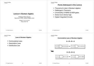
  • 1. Points Addressed in this Lecture • Theorems & rules in Boolean algebra • DeMorgan’s Theorems • Universality of NAND & NOR gates Lecture 4: Boolean Algebra • Active low & Active high Professor Peter Cheung • Digital Integrated Circuits Department of EEE, Imperial College London (Floyd 4.1-4.4, 5.2-5.4) (Tocci 3.8-3.14) E1.2 Digital Electronics I 4.1 Oct 2007 E1.2 Digital Electronics I Oct 2007 Laws of Boolean Algebra Commutative Laws of Boolean Algebra • Commutative Laws A+B=B+A • Associative Laws • Distributive Law A•B=B•A E1.2 Digital Electronics I 4.3 Oct 2007 E1.2 Digital Electronics I 4.4 Oct 2007
  • 2. Associative Laws of Boolean Algebra Distributive Laws of Boolean Algebra A • (B + C) = A • B + A • C A + (B + C) = (A + B) + C A (B + C) = A B + A C A • (B • C) = (A • B) • C E1.2 Digital Electronics I 4.5 Oct 2007 E1.2 Digital Electronics I 4.6 Oct 2007 Rules of Boolean Algebra Rules of Boolean Algebra • Rule 1 OR Truth Table • Rule 2 • Rule 3 AND Truth Table • Rule 4 E1.2 Digital Electronics I 4.7 Oct 2007 E1.2 Digital Electronics I 4.8 Oct 2007
  • 3. Rules of Boolean Algebra Rules of Boolean Algebra • Rule 5 • Rule 9 • Rule 10: A + AB = A OR Truth Table • Rule 6 AND Truth Table OR Truth Table • Rule 7 AND Truth Table • Rule 8 E1.2 Digital Electronics I 4.9 Oct 2007 E1.2 Digital Electronics I 4.10 Oct 2007 Rules of Boolean Algebra Examples • Rule 11: A + AB = A + B • Simplify the expression y = ABD + ABD y = AB • Simplify ( ) z = A + B (A + B ) z=B • Rule 12: (A + B)(A + C) = A + BC • Simplify x = ACD+ ABCD x = ACD + BCD E1.2 Digital Electronics I 4.11 Oct 2007 E1.2 Digital Electronics I 4.12 Oct 2007
  • 4. DeMorgan’s Theorems Review Questions • Theorem 1 y = AC + AB C • Simplify (x + y ) = x ⋅ y Remember: y = AC “Break the bar, • Theorem 2 change the operator” • Simplify y = ABC D + ABC D (x ⋅ y ) = x + y y = AB D – DeMorgan's theorem is very useful in digital circuit design – It allows ANDs to be exchanged with ORs by using invertors • Simplify y = AD + ABD – DeMorgan's Theorem can be extended to any number of variables. y = AD + BD E1.2 Digital Electronics I 4.13 Oct 2007 E1.2 Digital Electronics I 4.14 Oct 2007 Example of DeMorgan’s Theorem Example • Simplify the expression F = X .Y + P.Q 2 NAND plus 1 OR 1 OR with some input invertors ( )( z = A+ C ⋅ B + D ) = X +Y + P +Q to one having only single variables inverted. z = AC + B D E1.2 Digital Electronics I 4.15 Oct 2007 E1.2 Digital Electronics I 4.16 Oct 2007
  • 5. Implications of DeMorgan’s Theorems(I) Implications of DeMorgan’s Theorems(II) E1.2 Digital Electronics I 4.17 Oct 2007 E1.2 Digital Electronics I 4.18 Oct 2007 Example Review Questions • Determine the output expression for the below • Using DeMorgan’s Theorems to convert the circuit and simplify it using DeMorgan’s expressions to one that has only single-variable Theorem inversions. y = R ST + Q y = ( R + S + T )Q z = ( A + B )⋅ C z = AB + C • Use DeMorgan’s theorems to convert below expression to an expression containing only single-variable inversions. y = A + B + CD y = A B(C + D ) E1.2 Digital Electronics I 4.19 Oct 2007 E1.2 Digital Electronics I 4.20 Oct 2007
  • 6. Universality of NAND gates Universality of NOR gate E1.2 Digital Electronics I 4.21 Oct 2007 E1.2 Digital Electronics I 4.22 Oct 2007 Basic Characteristics of Digital ICs • Digital ICs (chips): a collection of resistors, diodes and transistors fabricated on a single piece of semiconductor materials called substrate. • Dual-in-line package (DIP) is a common type of packages. Logic probe is used to monitor the logic level activity at an IC pin or any other accessible point in a logic circuit E1.2 Digital Electronics I 4.23 Oct 2007 E1.2 Digital Electronics I 4.24 Oct 2007
  • 7. Example E1.2 Digital Electronics I 4.25 Oct 2007 E1.2 Digital Electronics I 4.26 Oct 2007 Alternate Logic-Gate Representations Obtain alternative symbol from standard ones • Invert each input and output of the standard symbol. This is done by adding bubbles(small circles) on input and output lines that do not have bubbles and by removing bubbles that are already there. • Change the operation symbol from AND to OR, or from OR to AND. (In the special case of the INVERTER, the operation symbol is not changed.) E1.2 Digital Electronics I 4.27 Oct 2007 E1.2 Digital Electronics I 4.28 Oct 2007
  • 8. Several points Logic-symbol interpretation • The equivalences can be extended to gates with any number of inputs. • Active high/low • None of the standard symbols have bubbles on their – When an input or output line on a logic circuit inputs, and all the alternate symbols do. symbol has no bubble on it, that line is said to • The standard and alternate symbols for each gate be active-high, otherwise it is active-low. represent the same physical circuit; there is no difference in the circuits represented by the two symbols. • NAND and NOR gates are inverting gates, and so both the standard and the alternate symbols for each will have a bubble on either the input or the output, AND and OR gates are non-inverting gates, and so the alternate symbols for each will have bubbles on both inputs and output. E1.2 Digital Electronics I 4.29 Oct 2007 E1.2 Digital Electronics I 4.30 Oct 2007 Interpretation of the two NAND gate symbols Interpretation of the two OR gate symbols E1.2 Digital Electronics I 4.31 Oct 2007 E1.2 Digital Electronics I 4.32 Oct 2007
  • 9. Equivalency of three circuits • Which circuit diagram should be used? • Bubble placement Whenever possible, choose gate symbols so that bubble outputs are connected to bubble inputs, and nonbubble outputs to nonbubble inputs E1.2 Digital Electronics I 4.33 Oct 2007 E1.2 Digital Electronics I 4.34 Oct 2007 Active High & Active Low Representations • When a logic signal is in its active state, it can be said to be asserted (=activated). When a logic signal is not in its active state, it is said to be unasserted (=inactive). • The overbar is simply a way to emphasize that these are active-LOW signals. E1.2 Digital Electronics I 4.35 Oct 2007 E1.2 Digital Electronics I 4.36 Oct 2007
  • 10. Summary: Summary How to represent the basic logic functions • Boolean Algebra: a mathematical tool used in the analysis and design of digital circuits • Logical statements in our own language • OR, AND, NOT: basic Boolean operations • Truth tables • OR: HIGH output when any input is HIGH • AND: HIGH output only when all inputs are HIGH • Traditional graphic logic symbols • NOT: output is the opposite logic level as the input • Boolean algebra expressions • NOR: OR with its output connected to an INVERTER • Timing diagrams • NAND: AND with its output connected to an INVERTER • Boolean theorems and rules: to simplify the expression of a logic circuit and can lead to a simpler way of implementing the circuit • NAND, NOR: can be used to implement any of the basic Boolean operations E1.2 Digital Electronics I 4.37 Oct 2007 E1.2 Digital Electronics I 4.38 Oct 2007