SlideShare una empresa de Scribd logo
1 de 16
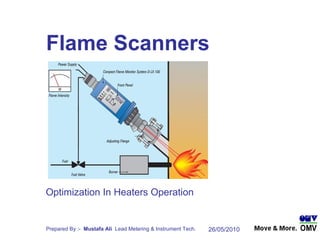
  Flame Scanners   Optimization In Heaters Operation
Introduction Flame whose UV radiation is absorbed by dust, water vapor or other material , may be monitored by these highly sensitive semiconductor UV photo elements,  These Flame monitors have also proven themselves in monitoring gas & oil combustion systems employing NOx reduction techniques , Flame scanners are used in burner applications with the widest variety of fuels,
Flame Scanners Installation at Heaters (Sawan CPP) 6 Scanners 6 Scanners 6 Scanners 6 Scanners 6 Scanners 6 Scanners 2 Scanners 2 Scanners
The photo elements used in the integrated optical flame scanner evaluate different spectral ranges of the flame. The pulses generated by the integrated flame scanners, which offer a  measure of the flame intensity, are transmitted to the microprocessor system and will trigger a flame ON or OFF signal, depending on the flame recognition threshold programmed in. ,[object Object],[object Object],[object Object],[object Object],Functional Description
Flame Scanners Malfunction Background / History Flame Scanners failure often occurs during Heaters Startup Pilot Flame Lit , but couldn’t recognized by Flame Scanner Several attempts to be made to run a Heater , Specially after S/D or Cold Startup Causing production delays, Causing excessive maintenance work hours utilization The Flame Threshold have adjustable Range of “0” Low Sensitivity to “ 9 “ High Sensitivity  in Flame Scanners, These Flame Scanners since Sawan Commissioning always set to “  9  ” Very low Pulse Frequency Threshold (High Sensitivity) to exposed Pilot Flame, That is to say, Very Narrow Flame Recognition Limit Therefore If the flame image is very intense or deteriorates too much the flame signal (pulse frequency) dips below or go over the shut-off threshold. The safety time programmed into the scanner will then begin to run. After the safety time expires, the flame OFF signal is given and the green LED goes out , fail-safe relay output to the external flame ON signal is open & Flame Failure occurred Flame Scanners Malfunction Cause
Threshold Rocker Switch Setting Graph
Threshold Settings Graph ( Conventional Practice Setting @ 9 ) Flame Scanners Rocker Switch set at “ 9 “ at All Sawan Heaters
4-20 mA Flame Intensity Feature not Utilized  4 – 20 mA Flame intensity signal wires were cut from cable & kept isolated in JB Every time a malfunction occurs,  Flame Scanner cover removes to excess the Flame Scanner & we couldn’t get the problem rectified without it,
Threshold Settings Graph ( Setting Optimized Recently @ 6 ) Methodology deployed & verified recently at Incinerator Train #1 & Train # 2
4-20mA Flame Intensity Feature Utilized Recently 4 – 20 mA Flame intensity signal wires were identified , Tagged & kept in JB for measuring Flame Intensity  at Incinerator Train # 1 & Train # 2
Discuss the observation among Instrument Team & prepare plan for implementation Performed job on Train # 2 Incinerator during S/D on 20 / 05 / 2010 Flame Scanner mA used for Flame Intensity has verified Flame Scanner Threshold Setting Change From  “9” to “6” Trouble Free Functionality checked Twice on startup of Incinerator Train # 2 Performed job on Train # 1 Incinerator during S/D on 23 / 05 / 2010 Flame Scanner mA used for Flame Intensity has verified Flame Scanner Threshold Setting Change From  “9” to “6” Trouble Free Functionality checked Twice on startup of Incinerator Train # 1 Action Taken
Way Forward Rocker Switch Threshold Adjustment at all the remaining Flame Scanners i,e “ 6 “  4 – 20 mA Flame intensity measurement at all the remaining Flame Scanners , Verify the Operation / Functionality of Flame Scanners
Flame must be visible to the flame scanner at all times, regardless of the load range of the burner. The 6° angle of view should always be oriented toward the root of the flame, that is, the bottom third of the flame. The flame scanner’s purge air connection is responsible for keeping the sighting tube and optics free of particles from the combustion chamber. Installation
The flame scanner is equipped with a push button switch for adjusting the flame recognition threshold .This threshold may be set to one of ten levels. Programming the Flame Scanner Flame OFF Setting: When burner is shut down, Threshold switch must be set high enough that the flame scanner does not see any ambient light and reliably signals ”Flame OFF”: •  the green”Flame” LED is not illuminated, •  the current in the flame intensity measurement circuit is less than 8 mA, •  the fail-safe relay output to the external flame ON signal is open. Flame ON Setting: If the burner is operating, Scanner must reliably exceed the flame recognition (shut-off) threshold and signal”Flame ON”: •  the green”Flame” LED is illuminated, •  the current in the flame intensity measurement circuit is greater than 12 mA •  the fail-safe relay output to the external flame ON signal is closed.
If the internal self-check recognizes an error in the safety-related software and hardware components, An error shutdown and internal lockout triggered. The relays for the flame, operational readiness and fault signals are released, and the red LED on the front panel will begin blinking. The contact from K1 signals the present fault. The red LED blinks 5 times by itself. After that, the yellow LED will also begin blinking with the red. Fault Recognition If the cause of the error is a defect in the integrated flame scanner, the red and green LED’s will blink alternately. The number of times that the yellow LED blinks corresponds to the type of error, which allows the operator to precisely analyze the source of the fault.
Flame Scanners Optimization In Heaters Operation Thanks For Kind Attention

Más contenido relacionado

La actualidad más candente

Turbine governing system an overview
Turbine governing system an overviewTurbine governing system an overview
Turbine governing system an overviewGaurav Kaushik
 
Sop of turbine lubrication oil system
Sop of turbine lubrication oil systemSop of turbine lubrication oil system
Sop of turbine lubrication oil systemAjit Kumar
 
Thermal Power Plant - Emergency situations
Thermal Power Plant   -   Emergency situations Thermal Power Plant   -   Emergency situations
Thermal Power Plant - Emergency situations Ashish Kumar Jain
 
Cfbc boiler startup and shutdown
Cfbc boiler startup and shutdownCfbc boiler startup and shutdown
Cfbc boiler startup and shutdownAshvani Shukla
 
210 mw turbine cycle heat rate
210 mw turbine cycle heat rate210 mw turbine cycle heat rate
210 mw turbine cycle heat rateManohar Tatwawadi
 
Effect of Coal Quality and Performance of Coal pulverisers / Mills
Effect of Coal Quality and Performance of Coal pulverisers / MillsEffect of Coal Quality and Performance of Coal pulverisers / Mills
Effect of Coal Quality and Performance of Coal pulverisers / MillsManohar Tatwawadi
 
Steam turbine over speed trip systems (6)
Steam turbine over speed trip systems (6)Steam turbine over speed trip systems (6)
Steam turbine over speed trip systems (6)Prem Baboo
 
Boiler Reheater protection
Boiler Reheater  protectionBoiler Reheater  protection
Boiler Reheater protectionanujkumarsingh79
 
Burner management-systems-a-technical-discussion-ppt
Burner management-systems-a-technical-discussion-pptBurner management-systems-a-technical-discussion-ppt
Burner management-systems-a-technical-discussion-pptmkpq pasha
 
Hydrogen Purge and Fill
Hydrogen Purge and FillHydrogen Purge and Fill
Hydrogen Purge and FillShad Edwards
 
Steam Turbine Performance in TPS
Steam Turbine Performance in TPSSteam Turbine Performance in TPS
Steam Turbine Performance in TPSManohar Tatwawadi
 
Furnace Guard Supervisory System (FSSS)
Furnace Guard Supervisory System (FSSS)Furnace Guard Supervisory System (FSSS)
Furnace Guard Supervisory System (FSSS)Jigyasa Singh
 
Heat rate audit in thermal power plant
Heat rate audit in thermal power plantHeat rate audit in thermal power plant
Heat rate audit in thermal power plantSHIVAJI CHOUDHURY
 

La actualidad más candente (20)

Turbine governing system an overview
Turbine governing system an overviewTurbine governing system an overview
Turbine governing system an overview
 
Sop of turbine lubrication oil system
Sop of turbine lubrication oil systemSop of turbine lubrication oil system
Sop of turbine lubrication oil system
 
Thermal Power Plant - Emergency situations
Thermal Power Plant   -   Emergency situations Thermal Power Plant   -   Emergency situations
Thermal Power Plant - Emergency situations
 
Cfbc boiler startup and shutdown
Cfbc boiler startup and shutdownCfbc boiler startup and shutdown
Cfbc boiler startup and shutdown
 
210 mw turbine cycle heat rate
210 mw turbine cycle heat rate210 mw turbine cycle heat rate
210 mw turbine cycle heat rate
 
Effect of Coal Quality and Performance of Coal pulverisers / Mills
Effect of Coal Quality and Performance of Coal pulverisers / MillsEffect of Coal Quality and Performance of Coal pulverisers / Mills
Effect of Coal Quality and Performance of Coal pulverisers / Mills
 
Steam turbine over speed trip systems (6)
Steam turbine over speed trip systems (6)Steam turbine over speed trip systems (6)
Steam turbine over speed trip systems (6)
 
200 mw FSSS
200 mw FSSS200 mw FSSS
200 mw FSSS
 
Boiler Reheater protection
Boiler Reheater  protectionBoiler Reheater  protection
Boiler Reheater protection
 
Burner management-systems-a-technical-discussion-ppt
Burner management-systems-a-technical-discussion-pptBurner management-systems-a-technical-discussion-ppt
Burner management-systems-a-technical-discussion-ppt
 
Hydrogen Purge and Fill
Hydrogen Purge and FillHydrogen Purge and Fill
Hydrogen Purge and Fill
 
Steam Turbine Performance in TPS
Steam Turbine Performance in TPSSteam Turbine Performance in TPS
Steam Turbine Performance in TPS
 
Furnace Guard Supervisory System (FSSS)
Furnace Guard Supervisory System (FSSS)Furnace Guard Supervisory System (FSSS)
Furnace Guard Supervisory System (FSSS)
 
Heat rate audit in thermal power plant
Heat rate audit in thermal power plantHeat rate audit in thermal power plant
Heat rate audit in thermal power plant
 
CFBC Boiler vs Pulverized Fired Boiler
CFBC Boiler vs Pulverized Fired BoilerCFBC Boiler vs Pulverized Fired Boiler
CFBC Boiler vs Pulverized Fired Boiler
 
Boiler Operation and Maintenance Experiences
Boiler Operation and Maintenance ExperiencesBoiler Operation and Maintenance Experiences
Boiler Operation and Maintenance Experiences
 
Gas turbine
Gas turbine Gas turbine
Gas turbine
 
Boiler Feedwater Pumps
Boiler Feedwater PumpsBoiler Feedwater Pumps
Boiler Feedwater Pumps
 
Stator water system chemistry
Stator water system chemistryStator water system chemistry
Stator water system chemistry
 
Heat balance diagram
Heat balance diagramHeat balance diagram
Heat balance diagram
 

Similar a Flame Scanners Optimization

Omni Guard 660 Flame Detector Presentation
Omni Guard 660 Flame Detector PresentationOmni Guard 660 Flame Detector Presentation
Omni Guard 660 Flame Detector PresentationMustafa Ali
 
General Monitors Flame Detectors Scp
General Monitors Flame Detectors ScpGeneral Monitors Flame Detectors Scp
General Monitors Flame Detectors ScpMustafa Ali
 
SenseTek Fireray 3000 installers handbook
SenseTek Fireray 3000 installers handbookSenseTek Fireray 3000 installers handbook
SenseTek Fireray 3000 installers handbookHans Bronkhorst
 
Safety siren pro series 3 radon gas detector user guide user manual
Safety siren pro series 3 radon gas detector user guide  user manualSafety siren pro series 3 radon gas detector user guide  user manual
Safety siren pro series 3 radon gas detector user guide user manualAshish Kamble
 
Qualification of High Performance Liquid Chromatography(HPLC)
Qualification of High Performance Liquid Chromatography(HPLC)Qualification of High Performance Liquid Chromatography(HPLC)
Qualification of High Performance Liquid Chromatography(HPLC)PRAVADA
 
Burner Management Flame Detection Requirements and Exceptions
Burner Management Flame Detection Requirements and ExceptionsBurner Management Flame Detection Requirements and Exceptions
Burner Management Flame Detection Requirements and ExceptionsKevin Maki
 
Manual de instalacion detector honeywell
Manual de instalacion detector honeywellManual de instalacion detector honeywell
Manual de instalacion detector honeywellCésar Ortiz Rincón
 
fire detection and alarm system
fire detection and alarm systemfire detection and alarm system
fire detection and alarm systemsingh1515
 
CO/CO2 level indicator Seminar
CO/CO2 level indicator SeminarCO/CO2 level indicator Seminar
CO/CO2 level indicator SeminarRavi Teja S V
 
Automatic gas detection system
Automatic  gas  detection  systemAutomatic  gas  detection  system
Automatic gas detection systemSayanSarkar55
 
Introduction of SG-O CIS / ALS / Light-Sensor Wafer Tester
Introduction of SG-O CIS / ALS / Light-Sensor Wafer TesterIntroduction of SG-O CIS / ALS / Light-Sensor Wafer Tester
Introduction of SG-O CIS / ALS / Light-Sensor Wafer TesterEnlitech
 
Why are fire detection & alarm system is required in buildings?
Why are fire detection & alarm system is required in buildings?Why are fire detection & alarm system is required in buildings?
Why are fire detection & alarm system is required in buildings?Shubham .
 
Automated Smoke Detected Exhaust Fan
Automated Smoke Detected Exhaust FanAutomated Smoke Detected Exhaust Fan
Automated Smoke Detected Exhaust FanHamzanadeem96
 

Similar a Flame Scanners Optimization (20)

Omni Guard 660 Flame Detector Presentation
Omni Guard 660 Flame Detector PresentationOmni Guard 660 Flame Detector Presentation
Omni Guard 660 Flame Detector Presentation
 
Flame Scanner.ppt
Flame Scanner.pptFlame Scanner.ppt
Flame Scanner.ppt
 
General Monitors Flame Detectors Scp
General Monitors Flame Detectors ScpGeneral Monitors Flame Detectors Scp
General Monitors Flame Detectors Scp
 
SenseTek Fireray 3000 installers handbook
SenseTek Fireray 3000 installers handbookSenseTek Fireray 3000 installers handbook
SenseTek Fireray 3000 installers handbook
 
Safety siren pro series 3 radon gas detector user guide user manual
Safety siren pro series 3 radon gas detector user guide  user manualSafety siren pro series 3 radon gas detector user guide  user manual
Safety siren pro series 3 radon gas detector user guide user manual
 
Oxygen Analyzer
Oxygen AnalyzerOxygen Analyzer
Oxygen Analyzer
 
Burner Controllers
Burner ControllersBurner Controllers
Burner Controllers
 
Qualification of High Performance Liquid Chromatography(HPLC)
Qualification of High Performance Liquid Chromatography(HPLC)Qualification of High Performance Liquid Chromatography(HPLC)
Qualification of High Performance Liquid Chromatography(HPLC)
 
Six channel fire monitoring & control
Six channel fire monitoring & controlSix channel fire monitoring & control
Six channel fire monitoring & control
 
Burner Management Flame Detection Requirements and Exceptions
Burner Management Flame Detection Requirements and ExceptionsBurner Management Flame Detection Requirements and Exceptions
Burner Management Flame Detection Requirements and Exceptions
 
Smoke Detection System
Smoke Detection SystemSmoke Detection System
Smoke Detection System
 
Manual de instalacion detector honeywell
Manual de instalacion detector honeywellManual de instalacion detector honeywell
Manual de instalacion detector honeywell
 
fire detection and alarm system
fire detection and alarm systemfire detection and alarm system
fire detection and alarm system
 
Fire alarm systems
Fire alarm systemsFire alarm systems
Fire alarm systems
 
CO/CO2 level indicator Seminar
CO/CO2 level indicator SeminarCO/CO2 level indicator Seminar
CO/CO2 level indicator Seminar
 
Eclipse manual
Eclipse manualEclipse manual
Eclipse manual
 
Automatic gas detection system
Automatic  gas  detection  systemAutomatic  gas  detection  system
Automatic gas detection system
 
Introduction of SG-O CIS / ALS / Light-Sensor Wafer Tester
Introduction of SG-O CIS / ALS / Light-Sensor Wafer TesterIntroduction of SG-O CIS / ALS / Light-Sensor Wafer Tester
Introduction of SG-O CIS / ALS / Light-Sensor Wafer Tester
 
Why are fire detection & alarm system is required in buildings?
Why are fire detection & alarm system is required in buildings?Why are fire detection & alarm system is required in buildings?
Why are fire detection & alarm system is required in buildings?
 
Automated Smoke Detected Exhaust Fan
Automated Smoke Detected Exhaust FanAutomated Smoke Detected Exhaust Fan
Automated Smoke Detected Exhaust Fan
 

Flame Scanners Optimization

  • 1. Flame Scanners Optimization In Heaters Operation
  • 2. Introduction Flame whose UV radiation is absorbed by dust, water vapor or other material , may be monitored by these highly sensitive semiconductor UV photo elements, These Flame monitors have also proven themselves in monitoring gas & oil combustion systems employing NOx reduction techniques , Flame scanners are used in burner applications with the widest variety of fuels,
  • 3. Flame Scanners Installation at Heaters (Sawan CPP) 6 Scanners 6 Scanners 6 Scanners 6 Scanners 6 Scanners 6 Scanners 2 Scanners 2 Scanners
  • 4.
  • 5. Flame Scanners Malfunction Background / History Flame Scanners failure often occurs during Heaters Startup Pilot Flame Lit , but couldn’t recognized by Flame Scanner Several attempts to be made to run a Heater , Specially after S/D or Cold Startup Causing production delays, Causing excessive maintenance work hours utilization The Flame Threshold have adjustable Range of “0” Low Sensitivity to “ 9 “ High Sensitivity in Flame Scanners, These Flame Scanners since Sawan Commissioning always set to “ 9 ” Very low Pulse Frequency Threshold (High Sensitivity) to exposed Pilot Flame, That is to say, Very Narrow Flame Recognition Limit Therefore If the flame image is very intense or deteriorates too much the flame signal (pulse frequency) dips below or go over the shut-off threshold. The safety time programmed into the scanner will then begin to run. After the safety time expires, the flame OFF signal is given and the green LED goes out , fail-safe relay output to the external flame ON signal is open & Flame Failure occurred Flame Scanners Malfunction Cause
  • 6. Threshold Rocker Switch Setting Graph
  • 7. Threshold Settings Graph ( Conventional Practice Setting @ 9 ) Flame Scanners Rocker Switch set at “ 9 “ at All Sawan Heaters
  • 8. 4-20 mA Flame Intensity Feature not Utilized 4 – 20 mA Flame intensity signal wires were cut from cable & kept isolated in JB Every time a malfunction occurs, Flame Scanner cover removes to excess the Flame Scanner & we couldn’t get the problem rectified without it,
  • 9. Threshold Settings Graph ( Setting Optimized Recently @ 6 ) Methodology deployed & verified recently at Incinerator Train #1 & Train # 2
  • 10. 4-20mA Flame Intensity Feature Utilized Recently 4 – 20 mA Flame intensity signal wires were identified , Tagged & kept in JB for measuring Flame Intensity at Incinerator Train # 1 & Train # 2
  • 11. Discuss the observation among Instrument Team & prepare plan for implementation Performed job on Train # 2 Incinerator during S/D on 20 / 05 / 2010 Flame Scanner mA used for Flame Intensity has verified Flame Scanner Threshold Setting Change From “9” to “6” Trouble Free Functionality checked Twice on startup of Incinerator Train # 2 Performed job on Train # 1 Incinerator during S/D on 23 / 05 / 2010 Flame Scanner mA used for Flame Intensity has verified Flame Scanner Threshold Setting Change From “9” to “6” Trouble Free Functionality checked Twice on startup of Incinerator Train # 1 Action Taken
  • 12. Way Forward Rocker Switch Threshold Adjustment at all the remaining Flame Scanners i,e “ 6 “ 4 – 20 mA Flame intensity measurement at all the remaining Flame Scanners , Verify the Operation / Functionality of Flame Scanners
  • 13. Flame must be visible to the flame scanner at all times, regardless of the load range of the burner. The 6° angle of view should always be oriented toward the root of the flame, that is, the bottom third of the flame. The flame scanner’s purge air connection is responsible for keeping the sighting tube and optics free of particles from the combustion chamber. Installation
  • 14. The flame scanner is equipped with a push button switch for adjusting the flame recognition threshold .This threshold may be set to one of ten levels. Programming the Flame Scanner Flame OFF Setting: When burner is shut down, Threshold switch must be set high enough that the flame scanner does not see any ambient light and reliably signals ”Flame OFF”: • the green”Flame” LED is not illuminated, • the current in the flame intensity measurement circuit is less than 8 mA, • the fail-safe relay output to the external flame ON signal is open. Flame ON Setting: If the burner is operating, Scanner must reliably exceed the flame recognition (shut-off) threshold and signal”Flame ON”: • the green”Flame” LED is illuminated, • the current in the flame intensity measurement circuit is greater than 12 mA • the fail-safe relay output to the external flame ON signal is closed.
  • 15. If the internal self-check recognizes an error in the safety-related software and hardware components, An error shutdown and internal lockout triggered. The relays for the flame, operational readiness and fault signals are released, and the red LED on the front panel will begin blinking. The contact from K1 signals the present fault. The red LED blinks 5 times by itself. After that, the yellow LED will also begin blinking with the red. Fault Recognition If the cause of the error is a defect in the integrated flame scanner, the red and green LED’s will blink alternately. The number of times that the yellow LED blinks corresponds to the type of error, which allows the operator to precisely analyze the source of the fault.
  • 16. Flame Scanners Optimization In Heaters Operation Thanks For Kind Attention