SAMPLE REVIT DRAWINGS-SUNIT K DHINGRA-COMPLETE - EASTWOODS
VILLAGE 1 STORM SEWER 0401 - 0411
1. 2TX
2TX
2TX
1
2TX
2TX
2TX
2TX
2TX
2TX
2TX
2TX
2TX
2TX
2TX
18,972 m²
152X131
Electric
Sub-Station 66kv
(40X40 M)
Special Plot
F
S
SS
S
S
S
S
S
S
S
S
SSSSSSS
S
S
S
S
SSSS
S
SS
S
S
S S
S
S
S
S
S
S
S
S
S
S
S
S
S
S
S
S
S
S
S S
S
S
SS
S S
S
SS
S S
S S S
S
SS
S
SS
S
SSS
S
SSSSS
S
S
S
S
S
SSS
S
SSS
S
S
S
S
S
SS
SS
S
S
SSS
SSS
S
SSS
SS
S
S
SS
S S
S
S
S
SSS
S
SSS
S
SS
S
SS
S
S
SS
S
S
S
S
∅
∅ ∅∅ SSSSSSSSSSSSSS
S
S
S
S
SSSSSSS
∅
N
Project
Stage
Title
Design Consultant
Scale
Checked Approved Date
JOD Drawing No. Rev
Prepared
Job No.
Rev Description Prep Chkd Appd Date
PJH
10011
DETAIL DESIGN
SOCIAL HOUSING PROJECT
AT EAST SITRA
Lead Consultants
Client
JOD-10011-C-CD-00-ST-PL-0401 -
Dec '15J.DN.C
1:1000@A1
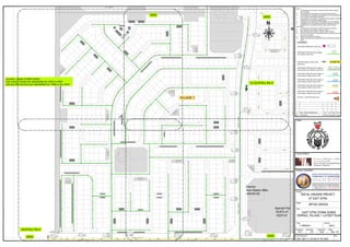
OVERALL VILLAGE 1 LAYOUT PLAN
EAST SITRA STORM SEWER
Dec '15PJHJDNCDraft DETAIL DESIGN IssueA
VILLAGE 1 MAIN STORM SEWER
FOR LAYOUT PLANS SEE DRAWINGS No. 0402 to 0405
FOR SECTION DETAILS SEE DRAWINGS No. 0406 to No. 0410
0403
0402
0404 0405
To OUTFALL No.4
LEGEND:
PROPOSED MANHOLE shown thus
PROPOSED PIPELINE within Villages
up to 600mm shown thus
PIPELINE NAME & DIRECTION
shown thus
PROPOSED PIPELINE within Village 10
(main arteries) up to 800mm shown thus
PROPOSED PIPELINE within Village 10
(main arteries) 1000mm shown thus
PROPOSED PIPELINE within Village 10
(main arteries) 1200mm shown thus
PROPOSED PIPELINE within Village 10
(main arteries) 1500mm shown thus
PROPOSED PIPELINE within Village 10
(main arteries) 1600mm shown thus
OUTFALL LOCATION shown thus
Notes
1. This Drawing is to be read in conjunction with all other relevant
documentation.
2. Do not scale from this drawing, use only printed dimensions.
3. All dimensions in millimetres, all chainages, levels and coordinates
are in metres unless defined otherwise.
4. This drawing is to be read in conjunction with the project Health and
Safety File for any identified potential risks.
5. All materials to be approved by EWA/SEPPD prior to installation.
6. Installation to be in accordance with SEPPD standards and best
practices and in accordance with the utility cross VILLAGE 1
SECTIONs.
7. All works to be carried out by a SEPPD approved contractor.
8. Pipe diameters up to 450mm, shall be of uPVC.
9. Pipe diameters above 450mm, shall be of GRP material.
10. Minimum clear cover from finish grade level to the top of pipe shall
be minimum 1200mm.
11. Minimum Pipe Size to be 300mm.
12. 150mm Dia Pipes to be used between Road Gullies and Collector
Pipes.
VILLAGE ? No.?
S
OUTFALL No.4
VILLAGE 1
2. 1
2TX
2TX
2TX
2TX
2TX
∅
∅
∅
∅
∅
∅ ∅
∅
∅
∅
∅
∅
∅
∅
∅
∅
∅
∅
∅
∅
∅ ∅
∅
∅ ∅
∅
∅
∅
∅
∅
∅
∅
∅
∅
S
SS
S
S
S
S
S
S
S
S
S
S
S
S
S
S
SS
S
S
S S
S
S
S
S
S
S
S
S
S
S
S
S
S
S
S
S
S
S
S S
S
S S S
SSS
S
S
S
S
S
SS
SS
S
S
S
S
S
S
S
SS
S S
S
∅
N
Project
Stage
Title
Design Consultant
Scale
Checked Approved Date
JOD Drawing No. Rev
Prepared
Job No.
Rev Description Prep Chkd Appd Date
PJH
10011
DETAIL DESIGN
SOCIAL HOUSING PROJECT
AT EAST SITRA
Lead Consultants
Client
JOD-10011-C-CD-00-ST-PL-0402 -
Dec '15J.DN.C
1:500@A1
SHEET 1 of 4
VILLAGE 1 LAYOUT PLAN
EAST SITRA STORM SEWER
Dec '15PJHJDNCDraft DETAIL DESIGN IssueA
SEE DRAWING -
JOD-10011-C-CD-00-ST-PL-0406 TO JOD-10011-C-CD-00-ST-PL-0409
FOR STORM SEWER SECTIONS
LEGEND:
PROPOSED MANHOLE shown thus
PROPOSED PIPELINE shown thus
VILLAGE 1 SECTION No. & DIRECTION
shown thus
PROPOSED PIPELINE within Asset 11
under seperate contract shown thu
ROAD GULLY & CONNECTION PIPE
shown thus
OUTFALL LOCATION shown thus
Notes
1. This Drawing is to be read in conjunction with all other relevant
documentation.
2. Do not scale from this drawing, use only printed dimensions.
3. All dimensions in millimetres, all chainages, levels and coordinates
are in metres unless defined otherwise.
4. This drawing is to be read in conjunction with the project Health and
Safety File for any identified potential risks.
5. All materials to be approved by EWA/SEPPD prior to installation.
6. Installation to be in accordance with SEPPD standards and best
practices and in accordance with the utility cross sections.
7. All works to be carried out by a SEPPD approved contractor.
8. Pipe diameters up to 450mm, shall be of uPVC.
9. Pipe diameters above 450mm, shall be of GRP material.
10. Minimum clear cover from finish grade level to the top of pipe shall
be minimum 1200mm.
No.10
S
ST GNo.?
NOTE :
REFER TO DRAWING JOD-10011-C-CD-00-ST-PL-0410, 0411,
0412 & 0413
FOR MANHOLE REPORT & CHAMBER DETAILS.
To OUTFALL No.4
No.2
No.1
No.1
No.1
No.2
No.3
No.4
No.5
No.6 No.7
No.6
No.8
No.8No.9
No.10
No.11
No.12
No.13
No.14
No.14
No.15
No.15
No.16
No.17
No.17
3. 1
2TX
2TX
2TX
2TX
∅
∅
∅
∅
∅
∅
∅ ∅
∅
∅
∅
∅
∅
∅∅∅
∅
∅
∅
∅∅∅
∅
∅
∅
∅
S
SS
S
S
S
S
S
S
S
SSSS
S
SS
S
S
S S
S
S
S
S
S
S
S
SSSSS
S
S
S
S
S
S
S
SSS
S
S
S
S
S
S
S
S
S
S S
∅
∅
∅∅
S
S
S
S
S
SS
S
S
S
SS
N
Project
Stage
Title
Design Consultant
Scale
Checked Approved Date
JOD Drawing No. Rev
Prepared
Job No.
Rev Description Prep Chkd Appd Date
PJH
10011
DETAIL DESIGN
SOCIAL HOUSING PROJECT
AT EAST SITRA
Lead Consultants
Client
JOD-10011-C-CD-00-ST-PL-0403 -
Dec '15J.DN.C
1:500@A1
SHEET 2 of 4
VILLAGE 1 LAYOUT PLAN
EAST SITRA STORM SEWER
Dec '15PJHJDNCDraft DETAIL DESIGN IssueA
SEE DRAWING -
JOD-10011-C-CD-00-ST-PL-0406
TO JOD-10011-C-CD-00-ST-PL-0409
FOR STORM SEWER SECTIONS
LEGEND:
PROPOSED MANHOLE shown thus
PROPOSED PIPELINE shown thus
VILLAGE 1 SECTION No. & DIRECTION
shown thus
PROPOSED PIPELINE within Asset 11
under seperate contract shown thu
ROAD GULLY & CONNECTION PIPE
shown thus
OUTFALL LOCATION shown thus
Notes
1. This Drawing is to be read in conjunction with all other relevant
documentation.
2. Do not scale from this drawing, use only printed dimensions.
3. All dimensions in millimetres, all chainages, levels and coordinates
are in metres unless defined otherwise.
4. This drawing is to be read in conjunction with the project Health and
Safety File for any identified potential risks.
5. All materials to be approved by EWA/SEPPD prior to installation.
6. Installation to be in accordance with SEPPD standards and best
practices and in accordance with the utility cross sections.
7. All works to be carried out by a SEPPD approved contractor.
8. Pipe diameters up to 450mm, shall be of uPVC.
9. Pipe diameters above 450mm, shall be of GRP material.
10. Minimum clear cover from finish grade level to the top of pipe shall
be minimum 1200mm.
No.10
S
ST GNo.?
NOTE :
REFER TO DRAWING JOD-10011-C-CD-00-ST-PL-0410, 0411,
0412 & 0413
FOR MANHOLE REPORT & CHAMBER DETAILS.
To OUTFALL No.4
No.1
No.15
No.15
No.17
No.17
No.1
No.2
No.8
No.12
No.13
No.14
No.14
No.15
No.18
No.18 No.19
No.21
No.18
4. 2TX
2TX
2TX
2TX
F
∅
∅
∅ ∅
∅
∅
∅ ∅
∅∅
∅∅
∅∅
∅
∅
∅
∅
∅
∅∅
∅∅
∅∅
∅
∅
∅∅∅∅
∅∅
∅
∅
∅∅
∅∅
∅
∅∅
SSSSSS
SS
S S
S
SS
S S S
S
SS
S
SS
S
SSS
S
S
SS
S
SS
SS
S
S
SSS
S
SS
S
S
SS
S
S
S
S
∅ SSSSSSSSS
S
S
∅
∅
∅
N
Project
Stage
Title
Design Consultant
Scale
Checked Approved Date
JOD Drawing No. Rev
Prepared
Job No.
Rev Description Prep Chkd Appd Date
PJH
10011
DETAIL DESIGN
SOCIAL HOUSING PROJECT
AT EAST SITRA
Lead Consultants
Client
JOD-10011-C-CD-00-ST-PL-0404 -
Dec '15J.DN.C
1:500@A1
SHEET 3 of 4
VILLAGE 1 LAYOUT PLAN
EAST SITRA STORM SEWER
Dec '15PJHJDNCDraft DETAIL DESIGN IssueA
SEE DRAWING -
JOD-10011-C-CD-00-ST-PL-0406
TO JOD-10011-C-CD-00-ST-PL-0409
FOR STORM SEWER SECTIONS
LEGEND:
PROPOSED MANHOLE shown thus
PROPOSED PIPELINE shown thus
VILLAGE 1 SECTION No. & DIRECTION
shown thus
PROPOSED PIPELINE within Asset 11
under seperate contract shown thu
ROAD GULLY & CONNECTION PIPE
shown thus
OUTFALL LOCATION shown thus
Notes
1. This Drawing is to be read in conjunction with all other relevant
documentation.
2. Do not scale from this drawing, use only printed dimensions.
3. All dimensions in millimetres, all chainages, levels and coordinates
are in metres unless defined otherwise.
4. This drawing is to be read in conjunction with the project Health and
Safety File for any identified potential risks.
5. All materials to be approved by EWA/SEPPD prior to installation.
6. Installation to be in accordance with SEPPD standards and best
practices and in accordance with the utility cross sections.
7. All works to be carried out by a SEPPD approved contractor.
8. Pipe diameters up to 450mm, shall be of uPVC.
9. Pipe diameters above 450mm, shall be of GRP material.
10. Minimum clear cover from finish grade level to the top of pipe shall
be minimum 1200mm.
No.10
S
ST GNo.?
NOTE :
REFER TO DRAWING JOD-10011-C-CD-00-ST-PL-0410, 0411,
0412 & 0413
FOR MANHOLE REPORT & CHAMBER DETAILS.
To OUTFALL
No.4
No.23
No.23
No.24
No.26
No.27
No.28
No.28
No.29 No.15
No.17
No.17
No.19
No.18
No.20
No.30
No.30
No.31
No.32
To OUTFALL
No.4
No.33
No.34
No.36
No.17
No.24
No.34
5. 2TX
2TX
1
2TX
2TX
2TX
Electric
Sub-Station 66kv
(40X40 M)
∅
∅
∅
∅
∅∅
∅
∅
∅∅∅ ∅
∅
∅∅∅
∅∅
∅
∅
∅∅∅∅
∅∅
∅
∅
∅∅
∅
∅
∅∅
∅∅
∅
∅∅
SS
S
SS
S
SSS
SSS
S
SS
SS
S
SS
S
S
S
SSS
S
SSS
S
SS
S
SS
S
S
SS
S
S
S
S
S
∅
∅∅
SSSSSSSS
SSSSS
S
N
Project
Stage
Title
Design Consultant
Scale
Checked Approved Date
JOD Drawing No. Rev
Prepared
Job No.
Rev Description Prep Chkd Appd Date
PJH
10011
DETAIL DESIGN
SOCIAL HOUSING PROJECT
AT EAST SITRA
Lead Consultants
Client
JOD-10011-C-CD-00-ST-PL-0405 -
Dec '15J.DN.C
1:500@A1
SHEET 4 of 4
VILLAGE 1 LAYOUT PLAN
EAST SITRA STORM SEWER
Dec '15PJHJDNCDraft DETAIL DESIGN IssueA
SEE DRAWING -
JOD-10011-C-CD-00-ST-PL-0406 to
JOD-10011-C-CD-00-ST-PL-0409
FOR STORM SEWER SECTIONS
LEGEND:
PROPOSED MANHOLE shown thus
PROPOSED PIPELINE shown thus
VILLAGE 1 SECTION No. & DIRECTION
shown thus
PROPOSED PIPELINE within Asset 11
under seperate contract shown thu
ROAD GULLY & CONNECTION PIPE
shown thus
OUTFALL LOCATION shown thus
Notes
1. This Drawing is to be read in conjunction with all other relevant
documentation.
2. Do not scale from this drawing, use only printed dimensions.
3. All dimensions in millimetres, all chainages, levels and coordinates
are in metres unless defined otherwise.
4. This drawing is to be read in conjunction with the project Health and
Safety File for any identified potential risks.
5. All materials to be approved by EWA/SEPPD prior to installation.
6. Installation to be in accordance with SEPPD standards and best
practices and in accordance with the utility cross sections.
7. All works to be carried out by a SEPPD approved contractor.
8. Pipe diameters up to 450mm, shall be of uPVC.
9. Pipe diameters above 450mm, shall be of GRP material.
10. Minimum clear cover from finish grade level to the top of pipe shall
be minimum 1200mm.
No.10
S
ST GNo.?
NOTE :
REFER TO DRAWING JOD-10011-C-CD-00-ST-PL-0410, 0411,
0412 & 0413
FOR MANHOLE REPORT & CHAMBER DETAILS.
TO OUTFALL No.4
No.18
No.18
No.17
No.17
No.19
No.20
No.30
No.30
No.31
No.32
No.33
No.34
No.34
No.36
No.36
No.35
No.15
No.25
No.36
No.22
6. Village No.1 Pipeline No.1 - OUTFALL No.4
-1
0
1
2
3
4
5
-2
-1
0
1
2
3
4
5
Pipe Dia.
Pipe Gradient
Prop. Ground Level
MH Cover Level & Chainage
Proposed Invert
Existing Ground Level
Chainage
2.740
2.740
2.740
2.740
2.740
2.740
2.740
2.740
2.740
2.740
2.740
2.740
2.740
2.740
2.740
2.740
2.740
2.740
2.740
2.740
2.740
2.740
2.740
2.740
2.740
2.740
2.740
2.740
2.740
2.740
Village No.1 Pipeline No.8 - OUTFALL No.4
-1
0
1
2
3
4
5
-2
-1
0
1
2
3
4
5
Pipe Dia.
Pipe Gradient
Prop. Ground Level
MH Cover Level & Chainage
Proposed Invert
Existing Ground Level
Chainage
Village No.1 Pipeline No.2 - OUTFALL No.4
-1
0
1
2
3
4
5
-2
-1
0
1
2
3
4
5
Pipe Dia.
Pipe Gradient
Prop. Ground Level
MH Cover Level & Chainage
Proposed Invert
Existing Ground Level
Chainage
Village No.1 Pipeline No.6 - OUTFALL No.4
-1
0
1
2
3
4
5
-2
-1
0
1
2
3
4
5
Pipe Dia.
Pipe Gradient
Prop. Ground Level
MH Cover Level & Chainage
Proposed Invert
Existing Ground Level
Chainage
2.740
2.740
2.740
2.740
2.740
2.740
2.740
2.740
2.740
2.740
2.740
2.740
Village No.1 Pipeline No.3 - OUTFALL No.4
-1
0
1
2
3
4
5
-2
-1
0
1
2
3
4
5
Pipe Dia.
Pipe Gradient
Prop. Ground Level
MH Cover Level & Chainage
Proposed Invert
Existing Ground Level
Chainage
Village No.1 Pipeline No.4 - OUTFALL No.4
-1
0
1
2
3
4
5
-2
-1
0
1
2
3
4
5
Pipe Dia.
Pipe Gradient
Prop. Ground Level
MH Cover Level & Chainage
Proposed Invert
Existing Ground Level
Chainage
Village No.1 Pipeline No.5 - OUTFALL No.4
-1
0
1
2
3
4
5
-2
-1
0
1
2
3
4
5
Pipe Dia.
Pipe Gradient
Prop. Ground Level
MH Cover Level & Chainage
Proposed Invert
Existing Ground Level
Chainage
2.740
2.740
2.740
2.740
2.740
2.740
2.740
2.740
2.740
2.740
2.740
2.740
2.740
2.740
2.740
2.740
2.740
2.740
2.740
2.740
2.740
2.740
2.740
2.740
Village No.1 Pipeline No.7 - OUTFALL No.4
-1
0
1
2
3
4
5
-2
-1
0
1
2
3
4
5
Pipe Dia.
Pipe Gradient
Prop. Ground Level
MH Cover Level & Chainage
Proposed Invert
Existing Ground Level
Chainage
2.740
2.740
2.740
2.740
2.740
2.740
2.740
2.740
2.740
2.740
2.740
2.740
2.740
2.740
2.740
2.740
2.740
2.740
2.740
2.740
Village No.1 Pipeline No.11 - OUTFALL No.4
-1
0
1
2
3
4
5
-2
-1
0
1
2
3
4
5
Pipe Dia.
Pipe Gradient
Prop. Ground Level
MH Cover Level & Chainage
Proposed Invert
Existing Ground Level
Chainage
Village No.1 Pipeline No.10 - OUTFALL No.4
-1
0
1
2
3
4
5
-2
-1
0
1
2
3
4
5
Pipe Dia.
Pipe Gradient
Prop. Ground Level
MH Cover Level & Chainage
Proposed Invert
Existing Ground Level
Chainage
Village No.1 Pipeline No.9 - OUTFALL No.4
-1
0
1
2
3
4
5
-2
-1
0
1
2
3
4
5
Pipe Dia.
Pipe Gradient
Prop. Ground Level
MH Cover Level & Chainage
Proposed Invert
Existing Ground Level
Chainage
2.740
2.740
2.740
2.740
2.740
2.740
2.740
2.740
2.740
2.740
2.740
2.740
Project
Stage
Title
Design Consultant
Scale
Checked Approved Date
JOD Drawing No. Rev
Prepared
Job No.
Rev Description Prep Chkd Appd Date
PJH
10011
DETAIL DESIGN
SOCIAL HOUSING PROJECT
AT EAST SITRA
Lead Consultants
Client
JOD-10011-C-CD-00-ST-PL-0406 -
Dec '15J.DN.C
1:1000@A1
SHEET 1 of 4
VILLAGE 1 SECTION
EAST SITRA STORM SEWER
Dec '15PJHJDNCDraft DETAIL DESIGN IssueA
SCALE = 1:1000 HORIZONTAL
1:100 VERTICAL
LEGEND:
PROPOSED MANHOLE shown thus
PROPOSED PIPELINE shown thus
VILLAGE 1 SECTION No. & DIRECTION
shown thus
PROPOSED PIPELINE within Asset 11
under seperate contract shown thu
ROAD GULLY & CONNECTION PIPE
shown thus
OUTFALL LOCATION shown thus
Notes
1. This Drawing is to be read in conjunction with all other relevant
documentation.
2. Do not scale from this drawing, use only printed dimensions.
3. All dimensions in millimetres, all chainages, levels and coordinates
are in metres unless defined otherwise.
4. This drawing is to be read in conjunction with the project Health and
Safety File for any identified potential risks.
5. All materials to be approved by EWA/SEPPD prior to installation.
6. Installation to be in accordance with SEPPD standards and best
practices and in accordance with the utility cross sections.
7. All works to be carried out by a SEPPD approved contractor.
8. Pipe diameters up to 450mm, shall be of uPVC.
9. Pipe diameters above 450mm, shall be of GRP material.
10. Minimum clear cover from finish grade level to the top of pipe shall
be minimum 1200mm.
No.10
S
ST GNo.?
NOTE :
REFER TO DRAWING JOD-10011-C-CD-00-ST-PL-0410, 0411,
0412 & 0413
FOR MANHOLE REPORT & CHAMBER DETAILS.
7. Village No.2 Pipeline No.16 - OUTFALL No.1
-1
0
1
2
3
4
5
-2
-1
0
1
2
3
4
5
Pipe Dia.
Pipe Gradient
Prop. Ground Level
MH Cover Level & Chainage
Proposed Invert
Existing Ground Level
Chainage
Village No.2 Pipeline No.14 - OUTFALL No.1
-1
0
1
2
3
4
5
-2
-1
0
1
2
3
4
5
Pipe Dia.
Pipe Gradient
Prop. Ground Level
MH Cover Level & Chainage
Proposed Invert
Existing Ground Level
Chainage
Village No.2 Pipeline No.11 - OUTFALL No.1
-1
0
1
2
3
4
5
Pipe Dia.
Pipe Gradient
Prop. Ground Level
MH Cover Level & Chainage
Proposed Invert
Existing Ground Level
Chainage
Village No.2 Pipeline No.12 - OUTFALL No.1
-1
0
1
2
3
4
5
-2
-1
0
1
2
3
4
5
Pipe Dia.
Pipe Gradient
Prop. Ground Level
MH Cover Level & Chainage
Proposed Invert
Existing Ground Level
Chainage
Village No.2 Pipeline No.10 - OUTFALL No.1
-1
0
1
2
3
4
5
-2
-1
0
1
2
3
4
5
Pipe Dia.
Pipe Gradient
Prop. Ground Level
MH Cover Level & Chainage
Proposed Invert
Existing Ground Level
Chainage
Village No.2 Pipeline No.6 - OUTFALL No.1
-1
0
1
2
3
4
5
-2
-1
0
1
2
3
4
5
Pipe Dia.
Pipe Gradient
Prop. Ground Level
MH Cover Level & Chainage
Proposed Invert
Existing Ground Level
Chainage
2.740
2.740
2.740
2.740
2.740
2.740
2.740
2.740
2.740
2.740
Village No.2 Pipeline No.7 - OUTFALL No.1
-1
0
1
2
3
4
5
-2
-1
0
1
2
3
4
5
Pipe Dia.
Pipe Gradient
Prop. Ground Level
MH Cover Level & Chainage
Proposed Invert
Existing Ground Level
Chainage
Village No.2 Pipeline No.9 - OUTFALL No.1
-1
0
1
2
3
4
5
-2
-1
0
1
2
3
4
5
Pipe Dia.
Pipe Gradient
Prop. Ground Level
MH Cover Level & Chainage
Proposed Invert
Existing Ground Level
Chainage
2.740
2.740
2.740
2.740
2.740
2.740
2.740
2.740
2.740
2.740
2.740
2.740
2.740
2.740
2.740
2.740
2.740
2.740
2.740
2.740
2.740
2.740
2.740
2.740
2.740
2.740
2.740
2.740
2.740
2.740
2.740
2.740
2.740
2.740
2.740
2.740
2.740
2.740
Village No.2 Pipeline No.41 - OUTFALL No.1
-1
0
1
2
3
4
5
-2
-1
0
1
2
3
4
5
Pipe Dia.
Pipe Gradient
Prop. Ground Level
MH Cover Level & Chainage
Proposed Invert
Existing Ground Level
Chainage
2.740
2.740
2.740
2.740
2.740
2.740
2.740
2.740
2.740
2.740
2.740
2.740
2.740
2.740
Village No.2 Pipeline No.15 - OUTFALL No.1
-1
0
1
2
3
4
5
Pipe Dia.
Pipe Gradient
Prop. Ground Level
MH Cover Level & Chainage
Proposed Invert
Existing Ground Level
Chainage
2.740
2.740
2.740
2.740
2.740
2.740
2.740
2.740
2.740
2.740
2.740
2.740
2.740
2.740
2.740
2.740
2.740
2.740
2.740
2.740
2.740
2.740
2.740
2.740
2.740
2.740
Village No.2 Pipeline No.8 - OUTFALL No.1
-1
0
1
2
3
4
5
-2
-1
0
1
2
3
4
5
Pipe Dia.
Pipe Gradient
Prop. Ground Level
MH Cover Level & Chainage
Proposed Invert
Existing Ground Level
Chainage
2.740
2.740
2.740
2.740
Project
Stage
Title
Design Consultant
Scale
Checked Approved Date
JOD Drawing No. Rev
Prepared
Job No.
Rev Description Prep Chkd Appd Date
PJH
10011
DETAIL DESIGN
SOCIAL HOUSING PROJECT
AT EAST SITRA
Lead Consultants
Client
JOD-10011-C-CD-00-ST-PL-0407 -
Dec '15J.DN.C
As Shown@A1
SHEET 2 of 4
VILLAGE 1 SECTION
EAST SITRA STORM SEWER
Dec '15PJHJDNCDraft DETAIL DESIGN IssueA
SCALE = 1:1000 HORIZONTAL
1:100 VERTICAL
LEGEND:
PROPOSED MANHOLE shown thus
PROPOSED PIPELINE shown thus
VILLAGE 1 SECTION No. & DIRECTION
shown thus
PROPOSED PIPELINE within Asset 11
under seperate contract shown thu
ROAD GULLY & CONNECTION PIPE
shown thus
OUTFALL LOCATION shown thus
Notes
1. This Drawing is to be read in conjunction with all other relevant
documentation.
2. Do not scale from this drawing, use only printed dimensions.
3. All dimensions in millimetres, all chainages, levels and coordinates
are in metres unless defined otherwise.
4. This drawing is to be read in conjunction with the project Health and
Safety File for any identified potential risks.
5. All materials to be approved by EWA/SEPPD prior to installation.
6. Installation to be in accordance with SEPPD standards and best
practices and in accordance with the utility cross sections.
7. All works to be carried out by a SEPPD approved contractor.
8. Pipe diameters up to 450mm, shall be of uPVC.
9. Pipe diameters above 450mm, shall be of GRP material.
10. Minimum clear cover from finish grade level to the top of pipe shall
be minimum 1200mm.
No.10
S
ST GNo.?
NOTE :
REFER TO DRAWING JOD-10011-C-CD-00-ST-PL-0410, 0411,
0412 & 0413
FOR MANHOLE REPORT & CHAMBER DETAILS.
8. Village No.2 Pipeline No.29 - OUTFALL No.1
-1
0
1
2
3
4
5
-2
-1
0
1
2
3
4
5
Pipe Dia.
Pipe Gradient
Prop. Ground Level
MH Cover Level & Chainage
Proposed Invert
Existing Ground Level
Chainage
Village No.2 Pipeline No.25 - OUTFALL No.1
-1
0
1
2
3
4
5
-2
-1
0
1
2
3
4
5
Pipe Dia.
Pipe Gradient
Prop. Ground Level
MH Cover Level & Chainage
Proposed Invert
Existing Ground Level
Chainage
Village No.2 Pipeline No.21 - OUTFALL No.1
-1
0
1
2
3
4
5
-2
-1
0
1
2
3
4
5
Pipe Dia.
Pipe Gradient
Prop. Ground Level
MH Cover Level & Chainage
Proposed Invert
Existing Ground Level
Chainage
Village No.2 Pipeline No.18 - OUTFALL No.1
-1
0
1
2
3
4
5
-2
-1
0
1
2
3
4
5
Pipe Dia.
Pipe Gradient
Prop. Ground Level
MH Cover Level & Chainage
Proposed Invert
Existing Ground Level
Chainage
Village No.2 Pipeline No.17 - OUTFALL No.1
-1
0
1
2
3
4
5
-2
-1
0
1
2
3
4
5
Pipe Dia.
Pipe Gradient
Prop. Ground Level
MH Cover Level & Chainage
Proposed Invert
Existing Ground Level
Chainage
Village No.2 Pipeline No.32 - OUTFALL No.1
-1
0
1
2
3
4
5
-2
-1
0
1
2
3
4
5
Pipe Dia.
Pipe Gradient
Prop. Ground Level
MH Cover Level & Chainage
Proposed Invert
Existing Ground Level
Chainage
Village No.2 Pipeline No.34 - OUTFALL No.1
-1
0
1
2
3
4
5
-2
-1
0
1
2
3
4
5
Pipe Dia.
Pipe Gradient
Prop. Ground Level
MH Cover Level & Chainage
Proposed Invert
Existing Ground Level
Chainage
2.740
2.740
2.740
2.740
2.740
2.740
2.740
2.740
2.740
2.740
2.740
2.740
2.740
2.740
2.740
2.740
2.740
2.740
Village No.2 Pipeline No.19 - OUTFALL No.1
-1
0
1
2
3
4
5
-2
-1
0
1
2
3
4
5
Pipe Dia.
Pipe Gradient
Prop. Ground Level
MH Cover Level & Chainage
Proposed Invert
Existing Ground Level
Chainage
Village No.2 Pipeline No.20 - OUTFALL No.1
-1
0
1
2
3
4
5
-2
-1
0
1
2
3
4
5
Pipe Dia.
Pipe Gradient
Prop. Ground Level
MH Cover Level & Chainage
Proposed Invert
Existing Ground Level
Chainage
2.740
2.740
2.740
2.740
2.740
2.740
2.740
2.740
2.740
2.740
2.740
2.740
2.740
2.740
2.740
2.740
2.740
2.740
2.740
2.740
Village No.2 Pipeline No.28 - OUTFALL No.1
-1
0
1
2
3
4
5
-2
-1
0
1
2
3
4
5
Pipe Dia.
Pipe Gradient
Prop. Ground Level
MH Cover Level & Chainage
Proposed Invert
Existing Ground Level
Chainage
Village No.2 Pipeline No.22 - OUTFALL No.1
-1
0
1
2
3
4
5
-2
-1
0
1
2
3
4
5
Pipe Dia.
Pipe Gradient
Prop. Ground Level
MH Cover Level & Chainage
Proposed Invert
Existing Ground Level
Chainage
Village No.2 Pipeline No.23 - OUTFALL No.1
-1
0
1
2
3
4
5
-2
-1
0
1
2
3
4
5
Pipe Dia.
Pipe Gradient
Prop. Ground Level
MH Cover Level & Chainage
Proposed Invert
Existing Ground Level
Chainage
Village No.2 Pipeline No.24 - OUTFALL No.1
-1
0
1
2
3
4
5
-2
-1
0
1
2
3
4
5
Pipe Dia.
Pipe Gradient
Prop. Ground Level
MH Cover Level & Chainage
Proposed Invert
Existing Ground Level
Chainage
2.740
2.740
2.740
2.740
2.740
2.740
2.740
2.740
2.740
2.740
2.740
2.740
2.740
2.740
2.740
2.740
2.740
2.740
2.740
2.740
2.740
2.740
Village No.2 Pipeline No.26 - OUTFALL No.1
-1
0
1
2
3
4
5
-2
-1
0
1
2
3
4
5
Pipe Dia.
Pipe Gradient
Prop. Ground Level
MH Cover Level & Chainage
Proposed Invert
Existing Ground Level
Chainage
2.740
2.740
2.740
2.740
2.740
2.740
2.740
2.740
2.740
2.740
2.740
2.740
2.740
2.740
2.740
2.740
2.740
2.740
2.740
2.740
2.740
2.740
2.740
2.740
2.740
2.740
2.740
2.740
2.740
2.740
Project
Stage
Title
Design Consultant
Scale
Checked Approved Date
JOD Drawing No. Rev
Prepared
Job No.
Rev Description Prep Chkd Appd Date
PJH
10011
DETAIL DESIGN
SOCIAL HOUSING PROJECT
AT EAST SITRA
Lead Consultants
Client
JOD-10011-C-CD-00-ST-PL-0408 -
Dec '15J.DN.C
As Shown@A1
SHEET 3 of 4
VILLAGE 1 SECTION
EAST SITRA STORM SEWER
Dec '15PJHJDNCDraft DETAIL DESIGN IssueA
SCALE = 1:1000 HORIZONTAL
1:100 VERTICAL
LEGEND:
PROPOSED MANHOLE shown thus
PROPOSED PIPELINE shown thus
VILLAGE 1 SECTION No. & DIRECTION
shown thus
PROPOSED PIPELINE within Asset 11
under seperate contract shown thu
ROAD GULLY & CONNECTION PIPE
shown thus
OUTFALL LOCATION shown thus
Notes
1. This Drawing is to be read in conjunction with all other relevant
documentation.
2. Do not scale from this drawing, use only printed dimensions.
3. All dimensions in millimetres, all chainages, levels and coordinates
are in metres unless defined otherwise.
4. This drawing is to be read in conjunction with the project Health and
Safety File for any identified potential risks.
5. All materials to be approved by EWA/SEPPD prior to installation.
6. Installation to be in accordance with SEPPD standards and best
practices and in accordance with the utility cross sections.
7. All works to be carried out by a SEPPD approved contractor.
8. Pipe diameters up to 450mm, shall be of uPVC.
9. Pipe diameters above 450mm, shall be of GRP material.
10. Minimum clear cover from finish grade level to the top of pipe shall
be minimum 1200mm.
No.10
S
ST GNo.?
NOTE :
REFER TO DRAWING JOD-10011-C-CD-00-ST-PL-0410, 0411,
0412 & 0413
FOR MANHOLE REPORT & CHAMBER DETAILS.
9. Village No.2 Pipeline No.38 - OUTFALL No.1
-1
0
1
2
3
4
5
-2
-1
0
1
2
3
4
5
Pipe Dia.
Pipe Gradient
Prop. Ground Level
MH Cover Level & Chainage
Proposed Invert
Existing Ground Level
Chainage
Village No.2 Pipeline No.13 - OUTFALL No.1
-1
0
1
2
3
4
5
-2
-1
0
1
2
3
4
5
Pipe Dia.
Pipe Gradient
Prop. Ground Level
MH Cover Level & Chainage
Proposed Invert
Existing Ground Level
Chainage
Village No.2 Pipeline No.35 - OUTFALL No.1
-1
0
1
2
3
4
5
-2
-1
0
1
2
3
4
5
Pipe Dia.
Pipe Gradient
Prop. Ground Level
MH Cover Level & Chainage
Proposed Invert
Existing Ground Level
Chainage
Village No.2 Pipeline No.33 - OUTFALL No.1
-1
0
1
2
3
4
5
-2
-1
0
1
2
3
4
5
Pipe Dia.
Pipe Gradient
Prop. Ground Level
MH Cover Level & Chainage
Proposed Invert
Existing Ground Level
Chainage
Village No.2 Pipeline No.27 - OUTFALL No.1
-1
0
1
2
3
4
5
-2
-1
0
1
2
3
4
5
Pipe Dia.
Pipe Gradient
Prop. Ground Level
MH Cover Level & Chainage
Proposed Invert
Existing Ground Level
Chainage
Village No.2 Pipeline No.30 - OUTFALL No.1
-1
0
1
2
3
4
5
-2
-1
0
1
2
3
4
5
Pipe Dia.
Pipe Gradient
Prop. Ground Level
MH Cover Level & Chainage
Proposed Invert
Existing Ground Level
Chainage
Village No.2 Pipeline No.31 - OUTFALL No.1
-1
0
1
2
3
4
5
-2
-1
0
1
2
3
4
5
Pipe Dia.
Pipe Gradient
Prop. Ground Level
MH Cover Level & Chainage
Proposed Invert
Existing Ground Level
Chainage
2.740
2.740
2.740
2.740
2.740
2.740
2.740
2.740
2.740
2.740
2.740
2.740
2.740
2.740
2.740
2.740
2.740
2.740
2.740
2.740
2.740
2.740
2.740
2.740
2.740
2.740
2.740
2.740
2.740
2.740
2.740
2.740
2.740
2.740
2.740
2.740
Village No.2 Pipeline No.40 - OUTFALL No.1
-1
0
1
2
3
4
5
-2
-1
0
1
2
3
4
5
Pipe Dia.
Pipe Gradient
Prop. Ground Level
MH Cover Level & Chainage
Proposed Invert
Existing Ground Level
Chainage
Village No.2 Pipeline No.36 - OUTFALL No.1
-1
0
1
2
3
4
5
-2
-1
0
1
2
3
4
5
Pipe Dia.
Pipe Gradient
Prop. Ground Level
MH Cover Level & Chainage
Proposed Invert
Existing Ground Level
Chainage
2.740
2.740
2.740
2.740
2.740
2.740
2.740
2.740
Village No.2 Pipeline No.37 - OUTFALL No.1
-1
0
1
2
3
4
5
-2
-1
0
1
2
3
4
5
Pipe Dia.
Pipe Gradient
Prop. Ground Level
MH Cover Level & Chainage
Proposed Invert
Existing Ground Level
Chainage
2.740
2.740
2.740
2.740
2.740
2.740
2.740
2.740
2.740
2.740
2.740
2.740
Village No.2 Pipeline No.39 - OUTFALL No.1
-1
0
1
2
3
4
5
-2
-1
0
1
2
3
4
5
Pipe Dia.
Pipe Gradient
Prop. Ground Level
MH Cover Level & Chainage
Proposed Invert
Existing Ground Level
Chainage
2.740
2.740
2.740
2.740
2.740
2.740
2.740
2.740
2.740
2.740
2.740
2.740
2.740
2.740
2.740
2.740
2.740
2.740
2.740
2.740
2.740
2.740
2.740
2.740
2.740
2.740
2.740
2.740
2.740
2.740
2.740
2.740
2.740
2.740
2.740
2.740
Village No.2 Pipeline No.42 - OUTFALL No.1
-1
0
1
2
3
4
5
-2
-1
0
1
2
3
4
5
Pipe Dia.
Pipe Gradient
Prop. Ground Level
MH Cover Level & Chainage
Proposed Invert
Existing Ground Level
Chainage
2.740
2.740
2.740
2.740
Project
Stage
Title
Design Consultant
Scale
Checked Approved Date
JOD Drawing No. Rev
Prepared
Job No.
Rev Description Prep Chkd Appd Date
PJH
10011
DETAIL DESIGN
SOCIAL HOUSING PROJECT
AT EAST SITRA
Lead Consultants
Client
JOD-10011-C-CD-00-ST-PL-0409 -
Dec '15J.DN.C
As Shown@A1
SHEET 4 of 4
VILLAGE 1 SECTION
EAST SITRA STORM SEWER
Dec '15PJHJDNCDraft DETAIL DESIGN IssueA
SCALE = 1:1000 HORIZONTAL
1:100 VERTICAL
LEGEND:
PROPOSED MANHOLE shown thus
PROPOSED PIPELINE shown thus
VILLAGE 1 SECTION No. & DIRECTION
shown thus
PROPOSED PIPELINE within Asset 11
under seperate contract shown thu
ROAD GULLY & CONNECTION PIPE
shown thus
OUTFALL LOCATION shown thus
Notes
1. This Drawing is to be read in conjunction with all other relevant
documentation.
2. Do not scale from this drawing, use only printed dimensions.
3. All dimensions in millimetres, all chainages, levels and coordinates
are in metres unless defined otherwise.
4. This drawing is to be read in conjunction with the project Health and
Safety File for any identified potential risks.
5. All materials to be approved by EWA/SEPPD prior to installation.
6. Installation to be in accordance with SEPPD standards and best
practices and in accordance with the utility cross sections.
7. All works to be carried out by a SEPPD approved contractor.
8. Pipe diameters up to 450mm, shall be of uPVC.
9. Pipe diameters above 450mm, shall be of GRP material.
10. Minimum clear cover from finish grade level to the top of pipe shall
be minimum 1200mm.
No.10
S
ST GNo.?
NOTE :
REFER TO DRAWING JOD-10011-C-CD-00-ST-PL-0410, 0411,
0412 & 0413
FOR MANHOLE REPORT & CHAMBER DETAILS.
10. 1:30 CROSSFALL
A
2001000200 250250
50
POSITION OF
ACCESS HOLE
HALF ROUND CHANNEL
1000 G POLYTHENE SHEET
250 1400 250
3000Max.300
MASTIC SEALANT 50x25mm THICK
WITH BOND BREAKER
MEMBRANE TOUNDRESIDE ONLY
RTR LINER IN ACCORDANCE WITH
SECTION 'F' OF THE SPECIFICATION
200
REINFORCEMENT BAR
MEDIUM OR HEAVY DUTY CAST IRON
COVER AND FRAME WITH RTR SEALING PLATE
ROAD LEVEL (PAVED AREAS)
COVER LEVEL -5
ROAD LEVEL (UNPAVED AREAS)
COVER LEVEL -50
GROUND LEVEL (OPEN AREAS)
COVER LEVEL -150
CONCRETE HAUNCH
GRADE C 45/20
PRECAST COVER SUPPORT PAINTED
INTERNALLY WITH EPOXY MORTAR
800
10mm THICK
EPOXY MORTAR
250mm THICK
CONCRETE WALL (C45/20)
CONCRETE BLINDING 50mm THICK
PAINT PROTECTION IN
ACCORDANCE WITH SECTION G
OF THE SPECIFICATION (TABLE G1)
BENCHING TO BE C45/20
CONCRETE FINISHED WITH
10mm THICK EPOXY MORTAR
3-3 T16-180 B
5 T16 145 B
5 T16 145 B
5 T16-145 B
1+4 T16-145 B
4 T16 TRIMMER BARS
310800790
550
1900
550 800
STORM
WATER
STO
R
M
W
ATER
STO
R
M
W
ATER
STO
R
M
W
ATER
STO
R
M
W
ATER
10 THICK EPOXY MORTAR
200 THICK CONCRETE WALL
(C45/20)
HALF ROUND CHANNEL
1000 G POLYTHENE SHEET
CONCRETE BLINDING 50 THICK
PAINT PROTECTION IN
ACCORDANCE WITH SECTION
G OF THE SPECIFICATION (TABLE G1)
200 800 200
2000Max.250
50
MEDIUM OR HEAVY DUTY CAST IRON
COVER AND FRAME WITH RTR SEALING PLATE
ROAD LEVEL (PAVED AREAS)
COVER LEVEL -5
ROAD LEVEL (UNPAVED AREAS)
COVER LEVEL -50
GROUND LEVEL (OPEN AREAS)
COVER LEVEL -150
CONCRETE HAUNCH
GRADE C 45/20
PRECAST COVER SUPPORT PAINTED
INTERNALLY WITH EPOXY MORTAR
1:30 CROSSFALL
A
1200
50 50
1:30 CROSSFALL
A
1001000100 250250
50
POSITION OF
ACCESS HOLE
3-3 T20-100 B
4 T20-200 B
4 T20-200 B
4 T20-200 B
1+5 T20-100 B
4 T20 TRIMMER BARS
300800600
450 450
1700
10mm THICK
EPOXY MORTAR
250mm THICK
CONCRETE WALL (C45/20)
HALF ROUND CHANNEL
1000 G POLYTHENE SHEET
CONCRETE BLINDING 50mm THICK
PAINT PROTECTION IN
ACCORDANCE WITH SECTION G
OF THE SPECIFICATION (TABLE G1)
250 1200 250
3000Max.300
BENCHING TO BE C45/20
CONCRETE FINISHED WITH
10mm THICK EPOXY MORTAR
MASTIC SEALANT 50x25 THICK WITH
BOND BREAKER MEMBRANE TO
UNDRESIDE ONLY
RTR LINER IN ACCORDANCE WITH
SECTION 'F' OF THE SPECIFICATION
200
REINFORCEMENT BAR
MEDIUM OR HEAVY DUTY CAST IRON
COVER AND FRAME WITH RTR SEALING PLATE
ROAD LEVEL (PAVED AREAS)
COVER LEVEL -5
ROAD LEVEL (UNPAVED AREAS)
COVER LEVEL -50
GROUND LEVEL (OPEN AREAS)
COVER LEVEL -150
CONCRETE HAUNCH
GRADE C 45/20
PRECAST COVER SUPPORT
PAINTED INTERNALLY WITH
EPOXY MORTAR
800
CHAMBER TYPE - D
PLAN
(SCALE 1:20)
SECTION - A
(SCALE 1:20)
CHAMBER TYPE - GREINFORCEMENT DETAILS
(SCALE-1:20)
STORM WATER CHAMBER HEAVY DUTY
COVER CLEAR OPENING 600x600
(SCALE 1:10)
STORM WATER CHAMBER HEAVY DUTY COVER
CLEAR OPENING 600Ø
(SCALE 1:10)
STORM WATER CHAMBER HEAVY DUTY
COVER CLEAR OPENING 675x675
(SCALE 1:10)
PLAN
(SCALE 1:20)
SECTION - A
(SCALE 1:20)
PLAN
(SCALE 1:20)
REINFORCEMENT DETAILS
(SCALE-1:20)
CHAMBER TYPE - F
SECTION - A
(SCALE 1:20)
Project
Stage
Title
Design Consultant
Scale
Checked Approved Date
JOD Drawing No. Rev
Prepared
Job No.
Rev Description Prep Chkd Appd Date
PJH
10011
DETAIL DESIGN
SOCIAL HOUSING PROJECT
AT EAST SITRA
Lead Consultants
Client
JOD-10011-C-CD-00-RD-PL-0410 -
Dec '15J.DN.C
As Shown@A1
& COVER TYPES OF VILLAGE 1
CHAMBER DETAILS TYPE D,F & G
STORM SEWER MANHOLE
Dec '15PJHJDNCDraft DETAIL DESIGN IssueA
Notes
1. This Drawing is to be read in conjunction with all other relevant
documentation.
2. Do not scale from this drawing, use only printed dimensions.
3. All dimensions in millimetres, all chainages, levels and coordinates
are in metres unless defined otherwise.
4. This drawing is to be read in conjunction with the project Health and
Safety File for any identified potential risks.
5. All materials to be approved by EWA/SEPPD prior to installation.
6. Installation to be in accordance with SEPPD standards and best
practices and in accordance with the utility cross sections.
7. All works to be carried out by a SEPPD approved contractor.
8. Pipe diameters up to 450mm, shall be of uPVC.
9. Pipe diameters above 450mm, shall be of GRP material.
10. Minimum clear cover from finish grade level to the top of pipe shall
be minimum 1200mm.
11. Project
Stage
Title
Design Consultant
Scale
Checked Approved Date
JOD Drawing No. Rev
Prepared
Job No.
Rev Description Prep Chkd Appd Date
PJH
10011
DETAIL DESIGN
SOCIAL HOUSING PROJECT
AT EAST SITRA
Lead Consultants
Client
JOD-10011-C-CD-00-RD-PL-0411 -
Dec '15J.DN.C
As Shown@A1
OF VILLAGE 1
REPORT
STORM SEWER MANHOLE
Dec '15PJHJDNCDraft DETAIL DESIGN IssueA
Notes
1. This Drawing is to be read in conjunction with all other relevant
documentation.
2. Do not scale from this drawing, use only printed dimensions.
3. All dimensions in millimetres, all chainages, levels and coordinates
are in metres unless defined otherwise.
4. This drawing is to be read in conjunction with the project Health and
Safety File for any identified potential risks.
5. All materials to be approved by EWA/SEPPD prior to installation.
6. Installation to be in accordance with SEPPD standards and best
practices and in accordance with the utility cross sections.
7. All works to be carried out by a SEPPD approved contractor.
8. Pipe diameters up to 450mm, shall be of uPVC.
9. Pipe diameters above 450mm, shall be of GRP material.
10. Minimum clear cover from finish grade level to the top of pipe shall
be minimum 1200mm.