SlideShare una empresa de Scribd logo
1 de 57
Descargar para leer sin conexión
DI1L4−17
−
DIAGNOSTICS ENGINE
DI−15
190
Author: Date:
2003 LEXUS LS430 (RM988U)
DIAGNOSTIC TROUBLE CODE CHART
HINT:
S As for the vehicle for Central America, refer to Repair Manual of 2002 LEXUS LS430 (Pub. No.
RM874U1).
S Parameters listed in the chart may not be exactly the same as your reading due to the type of instru-
ment or other factors.
If a malfunction code is displayed during the DTC check in check mode, check the circuit for the codes
listed in the table below. For details of each code, turn to the page referred to under the ’’See page’’
for the respective ’’DTC No.’’ in the DTC chart.
DTC No.
(See page)
Detection Item Trouble Area MIL*1 Memory
P0010
(DI−28)
Camshaft Position ”A” Actuator
Circuit (Bank 1)
S Open or short in OCV circuit
S OCV
S ECM
f f
P0011
(DI−32)
Camshaft Position ”A” −Timing
Over− Advanced or System Per-
formance (Bank 1)
S Valve timing
S OCV
S VVT controller assembly
S ECM
f f
P0012
(DI−32)
Camshaft Position ”A” −Timing
Over− Retarded (Bank 1)
S Valve timing
S OCV
S VVT controller assembly
S ECM
f f
P0016
(DI−39)
Crankshaft Position − Camshaft
Position Correlation (Bank 1
Sensor A)
S Open or short in VVT sensor circuit
S VVT sensor
S ECM
f f
P0018
(DI−39)
Crankshaft Position − Camshaft
Position Correlation (Bank 2
Sensor A)
S Open or short in VVT sensor circuit
S VVT sensor
S ECM
f f
P0020
(DI−28)
Camshaft Position ”A” Actuator
Circuit (Bank 2)
S Open or short in OCV circuit
S OCV
S ECM
f f
P0021
(DI−32)
Camshaft Position ”A” −Timing
Over− Advanced or System Per-
formance (Bank 2)
S Valve timing
S OCV
S VVT controller assembly
S ECM
f f
P0022
(DI−32)
Camshaft Position ”A” −Timing
Over− Retarded (Bank 2)
S Valve timing
S OCV
S VVT controller assembly
S ECM
f f
P0031
(DI−41)
Oxygen Sensor Heater Control
Circuit Low (Bank 1 Sensor 1)
S Open in heater circuit of heated oxygen sensor
S Heated oxygen sensor heater
S ECM
f f
P0032
(DI−41)
Oxygen Sensor Heater Control
Circuit High (Bank 1 Sensor 1)
S Short in heater circuit of heated oxygen sensor
S Heated oxygen sensor heater
S ECM
f f
P0037
(DI−41)
Oxygen Sensor Heater Control
Circuit Low (Bank 1 Sensor 2)
S Open in heater circuit of heated oxygen sensor
S Heated oxygen sensor heater
S EFI MAIN relay
S ECM
f f
P0038
(DI−41)
Oxygen Sensor Heater Control
Circuit High (Bank 1 Sensor 2)
S Short in heater circuit of heated oxygen sensor
S Heated oxygen sensor heater
S EFI MAIN relay
S ECM
f f
2
0
0
1
-
2
0
0
3
D
i
a
g
n
o
s
t
i
c
T
r
o
u
b
l
e
C
o
d
e
C
h
a
r
t
DI−16
−
DIAGNOSTICS ENGINE
191
Author: Date:
2003 LEXUS LS430 (RM988U)
P0051
(DI−41)
Oxygen Sensor Heater Control
Circuit Low (Bank 2 Sensor 1)
S Open in heater circuit of heated oxygen sensor
S Heated oxygen sensor heater
S ECM
f f
P0052
(DI−41)
Oxygen Sensor Heater Control
Circuit High (Bank 2 Sensor 1)
S Short in heater circuit of heated oxygen sensor
S Heated oxygen sensor heater
S ECM
f f
P0057
(DI−41)
Oxygen Sensor Heater Control
Circuit Low (Bank 2 Sensor 2)
S Open in heater circuit of heated oxygen sensor
S Heated oxygen sensor heater
S ECM
f f
P0058
(DI−41)
Oxygen Sensor Heater Control
Circuit High (Bank 2 Sensor 2)
S Short in heater circuit of heated oxygen sensor
S Heated oxygen sensor heater
S ECM
f f
P0100
(DI−47)
Mass or Volume Air Flow Circuit
S Open or short in mass air flow meter circuit
S Mass air flow meter
S ECM
f f
P0101
(DI−52)
Mass or Volume Air Flow Circuit
Range/Performance Problem
S Mass air flow meter f f
P0102
(DI−47)
Mass or Volume Air Flow Circuit
Low Input
S Open or short in mass air flow meter circuit
S Mass air flow meter
S ECM
f f
P0103
(DI−47)
Mass or Volume Air Flow Circuit
High Input
S Open in mass air flow meter circuit (EVG circuit)
S Short in mass air flow meter circuit (+B circuit)
S Mass air flow meter
S ECM
f f
P0110
(DI−53)
Intake Air Temperature Circuit
S Open or short in intake air temp. sensor circuit
S Intake air temp. sensor (built in mass air flow meter)
S ECM
f f
P0112
(DI−53)
Intake Air Temperature Circuit
Low Input
S Short in intake air temp. sensor circuit
S Intake air temp. sensor (built in mass air flow meter)
S ECM
f f
P0113
(DI−53)
Intake Air Temperature Circuit
High Input
S Open in intake air temp. sensor circuit
S Intake air temp. sensor (built in mass air flow meter)
S ECM
f f
P0115
(DI−58)
Engine Coolant Temperature Cir-
cuit
S Open or short in engine coolant temp. sensor circuit
S Engine coolant temp. sensor
S ECM
f f
P0116
(DI−62)
Engine Coolant Temperature Cir-
cuit Range/Performance Prob-
lem
S Cooling system
S Engine coolant temp. sensor
f f
P0117
(DI−58)
Engine Coolant Temperature Cir-
cuit Low Input
S Short in engine coolant temp. sensor circuit
S Engine coolant temp. sensor
S ECM
f f
P0118
(DI−58)
Engine Coolant Temperature Cir-
cuit High Input
S Open or short in engine coolant temp. sensor circuit
S Engine coolant temp. sensor
S ECM
f f
P0120
(DI−64)
Throttle Pedal Position Sensor/
Switch ”A” Circuit
S Open or short in throttle position sensor circuit
S Throttle position sensor
S ECM
f f
P0121
(DI−69)
Throttle/Pedal Position Sensor/
Switch ”A” Circuit Range/Perfor-
mance Problem
S Throttle position sensor f f
P0122
(DI−64)
Throttle/Pedal Position Sensor/
Switch ”A” Circuit Low Input
S Open in throttle position sensor circuit
S Throttle position sensor
S ECM
f f
2
0
0
1
-
2
0
0
3
D
i
a
g
n
o
s
t
i
c
T
r
o
u
b
l
e
C
o
d
e
C
h
a
r
t
−
DIAGNOSTICS ENGINE
DI−17
192
Author: Date:
2003 LEXUS LS430 (RM988U)
P0123
(DI−64)
Throttle/Pedal Position Sensor/
Switch ”A” Circuit High Input
S Short in throttle position sensor circuit
S Throttle position sensor
S ECM
f f
P0125
(DI−62)
Insufficient Coolant Temperature
for Closed Loop Fuel Control
S Cooling system
S Engine coolant temp. sensor
f f
P0128
(DI−70)
Coolant Thermostat (Coolant
Temperature Below Thermostat
Regulating Temperature)
S Thermostat
S Cooling system
S Engine coolant temp. sensor
S ECM
f f
P0130
(DI−71)
Oxygen Sensor Circuit
(Bank 1 Sensor 1)
S Open or short in heated oxygen sensor circuit (Bank 1 Sensor
1)
S Heated oxygen sensor (Bank 1 Sensor 1)
S Air induction system
S Fuel pressure
S Injector
S ECM
f f
P0133
(DI−75)
Oxygen Sensor Circuit Slow Re-
sponse (Bank 1 Sensor 1)
S Open or short in heated oxygen sensor circuit (Bank 1 Sensor
1)
S Heated oxygen sensor (Bank 1 Sensor 1)
S Air induction system
S Fuel pressure
S Injector
S ECM
f f
P0134
(DI−78)
Oxygen Sensor Circuit No Activ-
ity Detected (Bank 1 Sensor 1)
S Open or short in heated oxygen sensor circuit (Bank 1 Sensor
1)
S Heated oxygen sensor (Bank 1 Sensor 1)
S Air induction system
S Fuel pressure
S Injector
S Gas leakage on exhaust system
S PCV piping
S ECM
f f
P0136
(DI−82)
Oxygen Sensor Circuit Malfunc-
tion (Bank 1 Sensor 2)
S Open or short in heated oxygen sensor circuit (Bank 1 Sensor
2)
S Heated oxygen sensor (Bank 1 Sensor 2)
f f
P0150
(DI−71)
Oxygen Sensor Circuit
(Bank 2 Sensor 1)
S Open or short in heated oxygen sensor circuit (Bank 2 Sensor
1)
S Heated oxygen sensor (Bank 2 Sensor 1)
S Air induction system
S Fuel pressure
S Injector
S ECM
f f
P0153
(DI−75)
Oxygen Sensor Circuit Slow Re-
sponse (Bank 2 Sensor 1)
S Open or short in heated oxygen sensor circuit (Bank 2 Sensor
1)
S Heated oxygen sensor (Bank 2 Sensor 1)
S Air induction system
S Fuel pressure
S Injector
S ECM
f f
2
0
0
1
-
2
0
0
3
D
i
a
g
n
o
s
t
i
c
T
r
o
u
b
l
e
C
o
d
e
C
h
a
r
t
DI−18
−
DIAGNOSTICS ENGINE
193
Author: Date:
2003 LEXUS LS430 (RM988U)
P0154
(DI−78)
Oxygen Sensor Circuit No Activ-
ity Detected
S Open or short in heated oxygen sensor circuit (Bank 2 Sensor
1)
S Heated oxygen sensor (Bank 2 Sensor 1)
S Air induction system
S Fuel pressure
S Injector
S Gas leakage on exhaust system
S PCV piping
S ECM
f f
P0156
(DI−82)
Oxygen Sensor Circuit Malfunc-
tion (Bank 2 Sensor 2)
S Open or short in heated oxygen sensor circuit (Bank 2 Sensor
2)
S Heated oxygen sensor (Bank 2 Sensor 2)
f f
P0171
(DI−84)
System too Lean (Bank 1)
S Air induction system
S Injector blockage
S Mass air flow meter
S Engine coolant temp. sensor
S Fuel pressure
S Gas leakage on exhaust system
S Open or short in heated oxygen sensor (Bank 1 sensor 1)
circuit
S Heated oxygen sensor (Bank 1 sensor 1)
S PCV piping
S ECM
f f
P0172
(DI−84)
System too Rich (Bank 1)
S Injector leak, blockage
S Mass air flow meter
S Engine coolant temp. sensor
S Ignition system
S Fuel pressure
S Gas leakage on exhaust system
S Open or short in heated oxygen sensor (Bank 1 sensor 1)
circuit
S Heated oxygen sensor (Bank 1 sensor 1)
S ECM
f f
P0174
(DI−84)
System too Lean (Bank 2)
S Air induction system
S Injector blockage
S Mass air flow meter
S Engine coolant temp. sensor
S Fuel pressure
S Gas leakage on exhaust system
S Open or short in heated oxygen sensor (Bank 2 sensor 1)
circuit
S Heated oxygen sensor (Bank 2 sensor 1)
S PCV piping
S ECM
f f
P0175
(DI−84)
System too Rich (Bank 2)
S Injector leak, blockage
S Mass air flow meter
S Engine coolant temp. sensor
S Ignition system
S Fuel pressure
S Gas leakage in exhaust system
S Open or short in heated oxygen sensor (Bank 2 sensor 1)
circuit
S Heated oxygen sensor (Bank 2 sensor 1)
S ECM
f f
P0220
(DI−64)
Throttle/Pedal Position Sensor/
Switch ”B” Circuit
S Open or short in throttle position sensor circuit
S Throttle position sensor
S ECM
f f
2
0
0
1
-
2
0
0
3
D
i
a
g
n
o
s
t
i
c
T
r
o
u
b
l
e
C
o
d
e
C
h
a
r
t
−
DIAGNOSTICS ENGINE
DI−19
194
Author: Date:
2003 LEXUS LS430 (RM988U)
P0222
(DI−64)
Throttle/Pedal Position Sensor/
Switch ”B” Circuit Low Input
S Open in throttle position sensor circuit
S Throttle position sensor
S ECM
f f
P0223
(DI−64)
Throttle/Pedal Position Sensor/
Switch ”B” Circuit High Input
S Short in throttle position sensor circuit
S Throttle position sensor
S ECM
f f
P0230
(DI−89)
Fuel Pump Primary Circuit
S Open or short in fuel pump relay circuit
S Fuel pump relay
S ECM
− f
P0300
(DI−92)
Random/Multiple Cylinder Misfire
Detected
S Open or short in engine wire
S Connector connection
S Vacuum hose connection
S Ignition system
S Injector
S Fuel pressure
S Mass air flow meter
S Engine coolant temp. sensor
S Compression pressure
S Valve clearance
S Valve timing
S PCV piping
S ECM
f*2 f
P0301
(DI−92)
Cylinder 1 Misfire Detected f*2 f
P0302
(DI−92)
Cylinder 2 Misfire Detected f*2 f
P0303
(DI−92)
Cylinder 3 Misfire Detected f*2 f
P0304
(DI−92)
Cylinder 4 Misfire Detected f*2 f
P0305
(DI−92)
Cylinder 5 Misfire Detected f*2 f
P0306
(DI−92)
Cylinder 6 Misfire Detected f*2 f
P0307
(DI−92)
Cylinder 7 Misfire Detected f*2 f
P0308
(DI−92)
Cylinder 8 Misfire Detected f*2 f
P0325
(DI−102)
Knock Sensor 1 Circuit (Bank 1
or Single Sensor)
S Open or short in knock sensor 1 circuit
S Knock sensor 1 (looseness)
S ECM
f f
P0330
(DI−102)
Knock Sensor 2 Circuit (Bank 2)
S Open or short in knock sensor 2 circuit
S Knock sensor 2 (looseness)
S ECM
f f
P0335
(DI−106)
Crankshaft Position Sensor ”A”
Circuit
S Open or short in crankshaft position sensor circuit
S Crankshaft position sensor
S Signal plate (Timing belt guide)
S ECM
f f
P0339
(DI−108)
Crankshaft Position Sensor ”A”
Circuit Intermittent
S Open or short in crankshaft position sensor circuit
S Crankshaft position sensor
S Signal plate (Timing belt guide)
S ECM
− f
P0340
(DI−109)
Camshaft Position Sensor ”A”
Circuit (Bank 1 or Single Sensor) S Open or short in camshaft position sensor circuit
S VVT sensor
S ECM
f f
P0341
(DI−109)
Camshaft Position Sensor ”A”
Circuit Range/Performance
(Bank 1 or Single Sensor)
f f
P0345
(DI−109)
Camshaft Position Sensor ”A”
Circuit (Bank 2) S Open or short in camshaft position sensor circuit
S VVT sensor
S ECM
f f
P0346
(DI−109)
Camshaft Position Sensor ”A”
Circuit Range/Performance
(Bank 2)
f f
2
0
0
1
-
2
0
0
3
D
i
a
g
n
o
s
t
i
c
T
r
o
u
b
l
e
C
o
d
e
C
h
a
r
t
DI−20
−
DIAGNOSTICS ENGINE
195
Author: Date:
2003 LEXUS LS430 (RM988U)
P0351
(DI−112)
Ignition Coil ”A” Primary/Second-
ary Circuit
S Open or short in IF1L and IGT1 circuit from No. 1 ignition coil
with igniter to ECM
S No. 1 ignition coil with igniter
S Ignition system
S ECM
f f
P0352
(DI−112)
Ignition Coil ”B” Primary/Second-
ary Circuit
S Open or short in IF2R and IGT2 circuit from No. 2 ignition coil
with igniter to ECM
S No. 2 ignition coil with igniter
S Ignition system
S ECM
f f
P0353
(DI−112)
Ignition Coil ”C” Primary/Second-
ary Circuit
S Open or short in IF2L and IGT3 circuit from No. 3 ignition coil
with igniter to ECM
S No. 3 ignition coil with igniter
S Ignition system
S ECM
f f
P0354
(DI−112)
Ignition Coil ”D” Primary/Second-
ary Circuit
S Open or short in IF1R and IGT4 circuit from No. 4 ignition coil
with igniter to ECM
S No. 4 ignition coil with igniter
S Ignition system
S ECM
f f
P0355
(DI−112)
Ignition Coil ”E” Primary/Second-
ary Circuit
S Open or short in IF2L and IGT5 circuit from No. 5 ignition coil
with igniter to ECM
S No. 5 ignition coil with igniter
S Ignition system
S ECM
f f
P0356
(DI−112)
Ignition Coil ”F” Primary/Second-
ary Circuit
S Open or short in IF1R and IGT6 circuit from No. 6 ignition coil
with igniter to ECM
S No. 6 ignition coil with igniter
S Ignition system
S ECM
f f
P0357
(DI−112)
Ignition Coil ”G” Primary/Second-
ary Circuit
S Open or short in IF1L and IGT7 circuit from No. 7 ignition coil
with igniter to ECM
S No. 7 ignition coil with igniter
S Ignition system
S ECM
f f
P0358
(DI−112)
Ignition Coil ”H” Primary/Second-
ary Circuit
S Open or short in IF2R and IGT8 circuit from No. 8 ignition coil
with igniter to ECM
S No. 8 ignition coil with igniter
S Ignition system
S ECM
f f
P0420
(DI−119)
Catalyst System Efficiency Be-
low Threshold (Bank 1)
S Gas leakage on exhaust system
S Heated oxygen sensor (bank 1 sensor 1, 2)
S Three−way catalytic converter
f f
P0430
(DI−119)
Catalyst System Efficiency Be-
low Threshold (Bank 2)
S Gas leakage on exhaust system
S Heated oxygen sensor (bank 2 sensor 1, 2)
S Three−way catalytic converter
f f
2
0
0
1
-
2
0
0
3
D
i
a
g
n
o
s
t
i
c
T
r
o
u
b
l
e
C
o
d
e
C
h
a
r
t
−
DIAGNOSTICS ENGINE
DI−21
196
Author: Date:
2003 LEXUS LS430 (RM988U)
P0441
(DI−122)
Evaporative Emission Control
System Incorrect Purge Flow
S Vacuum hose cracks, holed, blocked, damaged or discon-
nected ((1), (2), (3), (4), (5), (6), (7), (8), (9), (10) and (11) in
Fig. 1)
S Fuel tank cap incorrectly installed
S Fuel tank cap cracked or damaged
S Open or short in vapor pressure sensor circuit
S Vapor pressure sensor
S Open or short in VSV circuit for EVAP
S VSV for EVAP
S Open or short in VSV circuit for CCV
S VSV for CCV
S Open or short in VSV circuit for pressure switching valve
S VSV for pressure switching valve
S Fuel tank cracked, holed or damaged
S Charcoal canister cracked, holed or damaged
S Fuel tank over fill check valve cracked or damaged
S ECM
f f
P0442
(DI−156)
Evaporative Emission Control
System Leak Detected (Small
Leak)
S Hose or tube cracked, holed, damaged or loose seal ((3) or (9)
in Fig. 1)
S Fuel tank cap incorrectly installed
S Fuel tank cap cracked or damaged
S Vacuum hose cracked, holed, blocked, damaged or discon-
nected ((1), (2), (4), (5), (6), (7), (8), (10) and (11) in Fig. 1)
S Fuel tank cracked, holed or damaged
S Charcoal canister cracked, holed or damaged
S Open or short in vapor pressure sensor circuit
S Vapor pressure sensor
S Fuel tank over fill check valve cracked or damaged
S ECM
f f
P0446
(DI−122)
Evaporative Emission Control
System Vent Control Circuit
S Same as DTC No. P0441 f f
P0451
(DI−178)
Evaporative Emission Control
System Pressure Sensor/Switch
Range/Performance
S Open or short in vapor pressure sensor circuit
S Vapor pressure sensor
S ECM
f f
P0452
(DI−178)
Evaporative Emission Control
System Pressure Sensor/Switch
Low Input
S Short in vapor pressure sensor circuit
S Vapor pressure sensor
S ECM
f f
P0453
(DI−178)
Evaporative Emission Control
System Pressure Sensor/Switch
High Input
S Open in vapor pressure sensor circuit
S Vapor pressure sensor
S ECM
f f
P0456
(DI−156)
Evaporative Emission Control
System Leak Detected (Very
Small Leak)
S Same as DTC No. P0442 f f
P0500
(DI−181)
Vehicle Speed Sensor ”A”
S Combination meter
S Open or short in vehicle speed sensor circuit
S Vehicle speed sensor
S ECM
f f
P0503
(DI−181)
Vehicle Speed Sensor ”A” Inter-
mittent/Erratic/High
S Combination meter
S Open or short in vehicle speed sensor circuit
S Vehicle speed sensor
S ECM
− f
P0504
(DI−184)
Brake Switch ”A”/”B” Correlation
S Stop light switch signal circuit
S Stop light switch
S ECM
− f
2
0
0
1
-
2
0
0
3
D
i
a
g
n
o
s
t
i
c
T
r
o
u
b
l
e
C
o
d
e
C
h
a
r
t
DI−22
−
DIAGNOSTICS ENGINE
197
Author: Date:
2003 LEXUS LS430 (RM988U)
P0505
(DI−187)
Idle Air Control System
S Air induction system
S Electric throttle control system
S Electric throttle control system circuit
S PCV piping
S ECM
f f
P0513
(DI−189)
Incorrect Immobilizer Key S Key − f
P0560
(DI−190)
System Voltage
S Open in back−up power source circuit
S EFI No.1 fuse
S ECM
f f
P0604
(DI−192)
Internal Control Module Random
Access Memory (RAM) Error
S ECM f f
P0606
(DI−192)
ECM/PCM Processor S ECM f f
P0607
(DI−192)
Control Module Performance S ECM f f
P0617
(DI−193)
Starter Relay Circuit High
S Park/neutral position switch
S Starter relay circuit
S Ignition switch
S ECM
f f
P0657
(DI−192)
Actuator Supply Voltage Circuit /
Open
S ECM f f
P1340
(DI−199)
Camshaft Position Sensor ”A”
Circuit (Bank 1 Sensor 2) S Open or short in camshaft position sensor circuit
S Camshaft position sensor
S LH camshaft timing pulley
S ECM
f f
P1341
(DI−199)
Camshaft Position Sensor ”A”
Circuit Range/Performance
(Bank 1 Sensor 2)
f f
P1645
(DI−201)
Body ECU Malfunction
S Body ECU
S A/C ECU
S Communication bus
f −
P2102
(DI−202)
Throttle Actuator Control Motor
Circuit Low
S Open in throttle control motor circuit
S Throttle control motor
S ECM
f f
P2103
(DI−202)
Throttle Actuator Control Motor
Circuit High
S Short in throttle control motor circuit
S Throttle control motor
S ECM
f f
P2111
(DI−206)
Throttle Actuator Control System
− Stuck Open
S Throttle control motor
S Throttle body
f f
P2112
(DI−206)
Throttle Actuator Control System
− Stuck Closed
S Throttle control motor
S Throttle body
f f
P2118
(DI−208)
Throttle Actuator Control Motor
Current Range/Performance
S Open in ETCS power source circuit
S ECM
f f
P2119
(DI−210)
Throttle Actuator Control Throttle
Body Range/Performance
S Electric throttle control system
S ECM
f f
P2120
(DI−212)
Throttle/Pedal Position Sensor/
Switch ”D” Circuit
S Open or short in accelerator pedal position sensor circuit
S Accelerator pedal position sensor
S ECM
f f
P2121
(DI−216)
Throttle/Pedal Position Sensor/
Switch ”D” Circuit Range/Perfor-
mance
S Accelerator pedal position sensor f f
P2122
(DI−212)
Throttle/Pedal Position Sensor/
Switch ”D” Circuit Low Input
S Open in accelerator pedal position sensor circuit
S Accelerator pedal position sensor
S ECM
f f
2
0
0
1
-
2
0
0
3
D
i
a
g
n
o
s
t
i
c
T
r
o
u
b
l
e
C
o
d
e
C
h
a
r
t
−
DIAGNOSTICS ENGINE
DI−23
198
Author: Date:
2003 LEXUS LS430 (RM988U)
P2123
(DI−212)
Throttle/Pedal Position Sensor/
Switch ”D” Circuit High Input
S Short in accelerator pedal position sensor circuit
S Accelerator pedal position sensor
S ECM
f f
P2125
(DI−212)
Throttle/Pedal Position Sensor/
Switch ”E” Circuit
S Short in accelerator pedal position sensor circuit
S Accelerator pedal position sensor
S ECM
f f
P2127
(DI−212)
Throttle/Pedal Position Sensor/
Switch ”E” Circuit Low Input
S Short in accelerator pedal position sensor circuit
S Accelerator pedal position sensor
S ECM
f f
P2128
(DI−212)
Throttle/Pedal Position Sensor/
Switch ”E” Circuit High Input
S Short in accelerator pedal position sensor circuit
S Accelerator pedal position sensor
S ECM
f f
P2135
(DI−64)
Throttle Pedal Position Sensor/
Switch ”A” / ”B” Voltage Correla-
tion
S VTA1 and VTA2 circuit are short−circuited
S Throttle position sensor
S ECM
f f
P2138
(DI−212)
Throttle/Pedal Position Sensor/
Switch ”D”/”E” Voltage Correla-
tion
S Short in accelerator pedal position sensor circuit
S Accelerator pedal position sensor
S ECM
f f
P2195
(DI−71)
Oxygen Sensor Signal Stuck
Lean (Bank 1 Sensor 1)
S Open or short in heated oxygen sensor circuit (Bank 1, 2 Sen-
sor 1)
S Heated oxygen sensor (Bank 1, 2 Sensor 1)
S EFI MAIN relay
S Air induction system
S Fuel pressure
S Injector
S ECM
f f
P2196
(DI−71)
Oxygen Sensor Signal Stuck
Rich (Bank 1 Sensor 1)
f f
P2197
(DI−71)
Oxygen Sensor Signal Stuck
Lean (Bank 2 Sensor 1)
f f
P2198
(DI−71)
Oxygen Sensor Signal Stuck
Rich (Bank 2 Sensor 1)
f f
*1: MIL lights up.
*2: MIL lights up or blinks.
*: − .... MIL does not light up, f .... MIL lights up
2
0
0
1
-
2
0
0
3
D
i
a
g
n
o
s
t
i
c
T
r
o
u
b
l
e
C
o
d
e
C
h
a
r
t
DI8E9−04
DI−248
−
DIAGNOSTICS AUTOMATIC TRANSMISSION
423
Author: Date:
2003 LEXUS LS430 (RM988U)
DIAGNOSTIC TROUBLE CODE CHART
HINT:
S As for the vehicle for Central America, refer to Repair Manual of 2002 LEXUS LS430 (Pub. No.
RM874U1).
S If a DTC is displayed during the DTC check, check the circuit listed in the table below and proceed to
the page given.
* : F...MIL light up
DTC No.
(See Page)
Detection Item Trouble Area MIL* Memory
P0500
(DI−258)
Vehicle Speed Sensor ”A”
S Open or short in vehicle speed sensor (SP2) circuit
S Speed sensor (SP2)
S ECM
S Automatic transmission assembly
F f
P0705
(DI−261)
Transmission Range Sensor Cir-
cuit Malfunction (PRNDL Input)
S Short in park/neutral position switch circuit
S Park/neutral position switch
S ECM
F f
P0710
(DI−265)
Transmission Fluid Temperature
Sensor ”A” Circuit
S Open or short in ATF temperature sensor circuit
S ATF temperature sensor
S ECM
F f
P0711
(DI−268)
Transmission Fluid Temperature
Sensor ”A” Performance
F f
P0712
(DI−265)
Transmission Fluid Temperature
Sensor ”A” Circuit Low Input
F f
P0713
(DI−265)
Transmission Fluid Temperature
Sensor ”A” Circuit High Input
F f
P0717
(DI−270)
Input Speed Sensor Circuit No
Signal
S Open or short in speed sensor (NC0) circuit
S Speed sensor (NC0)
S ECM
S Automatic transmission assembly
F f
P0724
(DI−273)
Brake Switch ”B” Circuit High
S Open or short in stop light switch signal circuit
S Stop light switch
S ECM
F f
P0751
(DI−274)
Shift Solenoid ”A” Performance
(Shift Solenoid Valve S1)
S Shift solenoid valve No. 1 is stuck open or closed
S Valve body is blocked up or stuck
S Automatic transmission assembly
F f
P0756
(DI−274)
Shift Solenoid ”B” Performance
(Shift Solenoid Valve S2)
S Shift solenoid valve No. 2 is stuck open or closed
S Valve body is blocked up or stuck
S Automatic transmission assembly
F f
P0761
(DI−274)
Shift Solenoid ”C” Performance
(Shift Solenoid Valve S3)
S Shift solenoid valve No. 3 is stuck open or closed
S Valve body is blocked up or stuck
S Automatic transmission assembly
F f
P0973
(DI−277)
Shift Solenoid ”A” Control Circuit
Low (Shift Solenoid Valve S1) S Open or short in shift solenoid valve No. 1 circuit
S Shift solenoid valve No. 1
S ECM
F f
P0974
(DI−277)
Shift Solenoid ”A” Control Circuit
High (Shift Solenoid Valve S1)
F f
P0976
(DI−277)
Shift Solenoid ”B” Control Circuit
Low (Shift Solenoid Valve S2) S Open or short in shift solenoid valve No. 2 circuit
S Shift solenoid valve No. 2
S ECM
F f
P0977
(DI−277)
Shift Solenoid ”B” Control Circuit
High (Shift Solenoid Valve S2)
F f
P0979
(DI−277)
Shift Solenoid ”C” Control Circuit
Low (Shift Solenoid Valve S3) S Open or short in shift solenoid valve No. 3 circuit
S Shift solenoid valve No. 3
S ECM
F f
P0980
(DI−277)
Shift Solenoid ”C” Control Circuit
High (Shift Solenoid Valve S3)
F f
2
0
0
1
-
2
0
0
3
D
i
a
g
n
o
s
t
i
c
T
r
o
u
b
l
e
C
o
d
e
C
h
a
r
t
−
DIAGNOSTICS AUTOMATIC TRANSMISSION
DI−249
424
Author: Date:
2003 LEXUS LS430 (RM988U)
P0982
(DI−283)
Shift Solenoid ”D” Control Circuit
Low (Shift Solenoid Valve S4) S Open or short in shift solenoid valve No. 4 circuit
S Shift solenoid valve No. 4
S ECM
F f
P0983
(DI−283)
Shift Solenoid ”D” Control Circuit
High (Shift Solenoid Valve S4)
F f
P2716
(DI−286)
Pressure Control Solenoid ”D”
Electrical
(Shift Solenoid Valve SLT)
S Open or short in shift solenoid valve SLT circuit
S Shift solenoid valve SLT
S ECM
F f
P2725
(DI−290)
Pressure Control Solenoid ”E”
Electrical
(Shift Solenoid Valve SLN)
S Open or short in shift solenoid valve SLN circuit
S Shift solenoid valve SLN
S ECM
F f
P2757
(DI−294)
Torque Converter Clutch Pres-
sure Control Solenoid Perfor-
mance
(Shift Solenoid Valve SLU)
S Shift solenoid valve SLU is stuck open or closed
S Valve body is blocked up or stuck
S Lock−up clutch
S Automatic transmission assembly
F f
P2759
(DI−296)
Torque Converter Clutch Pres-
sure Control Solenoid Control
Circuit Electrical
(Shift Solenoid Valve SLU)
S Open or short in shift solenoid valve SLU circuit
S Shift solenoid valve SLU
S ECM
F f
HINT:
This DTC may be output when the clutch, brake and gear components etc. inside the automatic transmission
are damaged.
2
0
0
1
-
2
0
0
3
D
i
a
g
n
o
s
t
i
c
T
r
o
u
b
l
e
C
o
d
e
C
h
a
r
t
DI0VS−07
DI−310
−
DIAGNOSTICS ELECTRONIC MODULATED AIR SUSPENSION
485
Author: Date:
2003 LEXUS LS430 (RM988U)
DIAGNOSTIC TROUBLE CODE CHART
HINT:
S Using SST 09843−18040, connect terminals Tc and CG of the DLC3.
S If any abnormality is not found when the parts are inspected, inspect the suspension control ECU.
S If a malfunction code is displayed during the DTC check, check the circuit listed for that code. For de-
tails of each code, turn to the page mentioned below ”DTC No.” in the DTC chart.
DTC No.
(See Page)
Detection Item Trouble Area
Indicator
Light*1 ( )*2
Memory*3
C1711 / 11
(DI−318)
Open or short circuit in right front
height control sensor circuit
S Right front, left front, right rear, left rear height control sensors
S Each height control sensor circuit
f (f) f
C1712 / 12
(DI−318)
Open or short circuit in left front
height control sensor circuit
f (f) f
C1713 / 13
(DI−318)
Open or short circuit in right rear
height control sensor circuit
f (f) f
C1714 / 14
(DI−318)
Open or short circuit in left rear
height control sensor circuit
f (f) f
C1715 / 15
(DI−323)
Open or short circuit in right front
acceleration sensor circuit
S Right front, left front, rear acceleration sensors
S Each acceleration sensor circuit
f (−) f
C1716 / 16
(DI−323)
Open or short circuit in left front
acceleration sensor circuit
f (−) f
C1717 / 17
(DI−323)
Open or short circuit in rear
acceleration sensor circuit
f (−) f
C1725 / 21
(DI−328)
Open or short circuit in right front
suspension control actuator
circuit
S Right front, left front, right rear, left rear suspension control
actuators
S Each suspension control actuator circuit
f (−) f
C1726 / 22
(DI−328)
Open or short circuit in left front
suspension control actuator
circuit
f (−) f
C1727 / 23
(DI−328)
Open or short circuit in right rear
suspension control actuator
circuit
f (−) f
C1728 / 24
(DI−328)
Open or short circuit in left rear
suspension control actuator
circuit
f (−) f
C1737 / 31
(DI−334)
Open or short circuit in right front
height control solenoid valve
circuit
S Right front, left front, right rear, left rear height control solenoid
valves
S Each height control solenoid valve circuit
f (f) f
C1739 / 32
(DI−334)
Open or short circuit in left front
height control solenoid valve
circuit
f (f) f
C1739 / 33
(DI−334)
Open or short circuit in right rear
height control solenoid valve
circuit
f (f) f
C1740 / 34
(DI−334)
Open or short circuit in left rear
height control solenoid valve
circuit
f (f) f
C1735 / 35
(DI−334)
Open or short circuit in height
control exhaust valve circuit
S Height control exhaust valve
S Height control exhaust valve circuit
f (f) f
C1741 / 41
(DI−341)
Open or short circuit in AIR SUS
relay circuit
S AIR SUS relay
S AIR SUS relay circuit
f (f) f
C1742 / 42
(DI−346)
Lock, open or short circuit in
height control compressor circuit
S Height control compressor
S Height control compressor circuit
f (f) f
2
0
0
1
-
2
0
0
3
D
i
a
g
n
o
s
t
i
c
T
r
o
u
b
l
e
C
o
d
e
C
h
a
r
t
−
DIAGNOSTICS ELECTRONIC MODULATED AIR SUSPENSION
DI−311
486
Author: Date:
2003 LEXUS LS430 (RM988U)
C1751 / 51*4
(DI−352)
Continuous electric current to
height control compressor circuit
S Height control compressor
S Height control compressor circuit
S Height control sensor link
S Height control sensor
S Relief valve
S Height control relay comes off
S Air leakage from the air tube or each valve
S Clogging in the air tube or each valve
f (−) f
C1752 / 52*5
(DI−354)
Continuous electric current to
height control exhaust valve
S Height control link
S Height control sensor
S Clogging in the air tube or each valve
f (−) f
C1774 / 74
(DI−355)
Power voltage drop
S Battery
S Power source circuit
f (−) −
C1776 / 76
(DI−360)
Vehicle speed sensor circuit
malfunction
S ABS speed sensor
S Vehicle speed sensor circuit
S Skid control ECU
f (−) f
C1777 / 77
(DI−362)
Open or short circuit in steering
angle sensor circuit
S Steering angle sensor
S Steering angle sensor circuit
f (−) f
C1778 / 78
(DI−365)
Open or short circuit in chassis
ECU (skid control ECU) commu-
nication circuit malfunction
S Skid control ECU
S Chassis ECU communication circuit
f (−) −
C1779 / 79
(DI−367)
Engine revolution signal circuit
malfunction
S Crankshaft position sensor
S Crankshaft position sensor circuit
S ECM
f (−) f
*1: For codes in the ”Indicator Light” column with a ”f” mark, the absorber control indicator light blinks at
1 second intervals.
*2: When a trouble occurs, ”HEIGHT HI” is displayed in the multi−information. Also, the master warning light
is lit on the combination meter and an alarm sounds.
*3: Codes with the ”f” mark in the ”Memory” column are stored in memory even when the ignition switch
is OFF. For codes with the ”−” mark, it does not memory.
*4: Since the relief pressure of the compressed air is 980 kPa (10 kgf/cm2, 142 psi), if the vehicle height con-
trol is attempted on a steeply sloping road, when the vehicle is overloaded, or when the vehicle height is
jacked up with the engine running, code ”C1751 / 51” may be output and vehicle height control may be sus-
pended. (This is not abnormal.) In this case, however, when detecting the first error, approx. 10 minutes after
the ignition switch was turned ON, vehicle height control is resumed. When the following errors are detected,
it takes 70 minutes until the control is resumed.
*5: If vehicle height control is operated while the wheels are removed or the vehicle is jacked up, code ”C1752
/ 52” may be output, but this is not abnormal. When code ”C1752 / 52” is output, the vehicle height control
is not carried out. However, the control is resumed if the ignition switch is turned OFF, then ON again.
2
0
0
1
-
2
0
0
3
D
i
a
g
n
o
s
t
i
c
T
r
o
u
b
l
e
C
o
d
e
C
h
a
r
t
DI0WA−13
DI−402 −
DIAGNOSTICS ABS WITH EBD  BA  TRAC  VSC SYSTEM AND
PROGRESSIVE POWER STEERING
577
Author: Date:
2003 LEXUS LS430 (RM988U)
DIAGNOSTIC TROUBLE CODE CHART
NOTICE:
Before replacing or removing the part, turn the ignition switch OFF.
HINT:
S Using SST 09843−18040, connect the terminals Tc and CG of DLC3.
S If any abnormality is not found on inspected parts, inspect the ECU.
S If a malfunction code is displayed during the DTC check, check the circuit indicated by DTC. For details
of each code, turn to the pages in the ”See page” for respective ”DTC No.” in the DTC chart.
DTC chart of ABS:
DTC No.
(See Page)
Detection Item Trouble Area
C0200 / 31*1
(DI−411)
Right front wheel speed sensor signal malfunction
S Right front, left front, right rear, left rear speed sensor
S Each speed sensor circuit
S Sensor rotor
C0205 / 32*1
(DI−411)
Left front wheel speed sensor signal malfunction
C0210 / 33*1
(DI−411)
Right rear wheel speed sensor signal malfunction
C0215 / 34*1
(DI−411)
Left rear wheel speed sensor signal malfunction
C0226 / 21
(DI−418)
Open or short circuit in brake actuator solenoid circuit
(SFR circuit)
S Brake actuator
S SFRH or SFRR circuit
C0236 / 22
(DI−418)
Open or short circuit in brake actuator solenoid circuit
(SFL circuit)
S Brake actuator
S SFLH or SFLR circuit
C0246 / 23
(DI−418)
Open or short circuit in brake actuator solenoid circuit
(SRR circuit)
S Brake actuator
S SRRH or SRRR circuit
C0256 / 24
(DI−418)
Open or short circuit in brake actuator solenoid circuit
(SRL circuit)
S Brake actuator
S SRLH or SRLR circuit
C0273 / 13*1
(DI−420)
Open circuit in ABS MTR relay circuit
S ABS MTR relay
S ABS MTR relay circuit
C0274 / 14
(DI−420)
Short circuit in ABS MTR relay circuit
C0278 / 11
(DI−424)
Open circuit in ABS SOL relay circuit
S ABS SOL relay
S ABS SOL relay circuit
C0279 / 12
(DI−424)
Short circuit in ABS SOL relay circuit
C1225 / 25
(DI−435)
Open or short circuit in brake actuator solenoid circuit
(SM circuit)
S Brake actuator
S SMF or SMR circuit
C1226 / 26
(DI−435)
Open or short circuit in brake actuator solenoid circuit
(SRM circuit)
S Brake actuator
S SRMF or SRMR circuit
C1227 / 27
(DI−435)
Open or short circuit in brake actuator solenoid circuit
(SRC circuit)
S Brake actuator
S SRCF or SRCR circuit
C1235 / 35
(DI−411)
Foreign matter is attached on the tip of the right front sensor
S Right front, left front, right rear, left rear speed sensor
S Sensor rotor
C1236 / 36
(DI−411)
Foreign matter is attached on the tip of the left front sensor
C1238 / 38
(DI−411)
Foreign matter is attached on the tip of the right rear sensor
C1239 / 39
(DI−411)
Foreign matter is attached on the tip of the left rear sensor
2
0
0
1
-
2
0
0
3
D
i
a
g
n
o
s
t
i
c
T
r
o
u
b
l
e
C
o
d
e
C
h
a
r
t
−
DIAGNOSTICS ABS WITH EBD  BA  TRAC  VSC SYSTEM AND
PROGRESSIVE POWER STEERING
DI−403
578
Author: Date:
2003 LEXUS LS430 (RM988U)
C1241 / 41
(DI−445)
Low battery positive voltage or abnormally high battery positive
voltage
S Battery
S Charging system
S Power source circuit
C1243 / 43*1
(DI−449)
Malfunction in deceleration sensor (constant output)
S Deceleration sensor
S Wire harness for deceleration sensor system
C1244 / 44
(DI−453)
Open or short circuit in deceleration sensor circuit
S Deceleration sensor
S Deceleration sensor circuit
C1245 / 45*1
(DI−449)
Malfunction in deceleration sensor
S Deceleration sensor
S Wire harness for deceleration sensor system
C1246 / 46*2
(DI−457)
Malfunction in master cylinder pressure sensor
S Master cylinder pressure sensor
S Master cylinder pressure sensor circuit
C1249 / 49
(DI−460)
Open circuit in stop light switch circuit
S Stop light bulb
S Stop light switch circuit
C1251 / 51*1
(DI−463)
ABS pump motor is locked
Open circuit in pump motor circuit
ABS pump motor
C1267 / 67
(DI−465)
Malfunction in brake pedal load sensing switch
S Brake pedal load sensing switch
S Brake pedal load sensing switch circuit
Always ON
(DI−473)
Malfunction in skid control ECU
S Power source circuit
S ABS warning light circuit
S Multiplex communication circuit
S Skid control ECU
*1, *2:
Even after the troubled areas are repaired, ABS warning light will not go OFF unless the following operations
are performed.
S *1:
(1) Drive the vehicle at 20 km/h (12 mph) for 30 seconds or more and check that the ABS warning
light goes off.
(2) Clear the DTC (See page DI−390).
S *2:
(1) Keep the vehicle in the stationary condition for 5 seconds or more and depress the brake pedal
lightly 2 or 3 times.
(2) Drive the vehicle at the vehicle speed 50 km/h (31 mph) and keep depressing the brake pedal
strongly for about 3 seconds.
(3) Repeat the above operation 3 times or more and check that the ABS warning light goes off.
(4) Clear the DTC (See page DI−390).
HINT:
There is a case that LEXUS hand−held tester cannot be used when ABS warning light is always on.
2
0
0
1
-
2
0
0
3
D
i
a
g
n
o
s
t
i
c
T
r
o
u
b
l
e
C
o
d
e
C
h
a
r
t
DI−404 −
DIAGNOSTICS ABS WITH EBD  BA  TRAC  VSC SYSTEM AND
PROGRESSIVE POWER STEERING
579
Author: Date:
2003 LEXUS LS430 (RM988U)
DTC chart of VSC:
DTC No.
(See Page)
Detection Item Trouble Area
C1201 / 51
(DI−428)
Malfunction in ECM Engine control system
C1202 / 52
(DI−429)
Brake fluid level low
Open circuit in brake fluid level warning switch circuit
S Brake fluid level
S Brake fluid level warning switch
S Brake fluid level warning switch circuit
C1203 / 53
(DI−431)
Malfunction in ECM communication circuit
S TRC+ or TRC− circuit
S ENG+ or ENG− circuit
S ECM
C1210 / 36
(DI−441)
Zero point calibration of yaw rate sensor undone
S Yaw rate sensor
S Yaw rate sensor circuit
S P position switch circuit
C1224 / 44
(DI−433)
Open or short circuit in NEO signal circuit
S NEO circuit
S ECM
C1231 / 31
(DI−437)
Malfunction in steering angle sensor
S Steering angle sensor
S Steering angle sensor circuit
C1232 / 32
(DI−453)
Malfunction in deceleration sensor (constant output)
S Deceleration sensor
S Deceleration sensor circuit
C1233 / 33
(DI−441)
Open or short circuit in yaw rate sensor circuit
S Yaw rate sensor
S Yaw rate sensor circuit
C1234 / 34
(DI−441)
Malfunction in yaw rate sensor
C1303 / 57
(DI−468)
Malfunction in multiplex communication circuit
S MPX1 circuit
S MPX2 circuit
C1335 / 35
(DI−437)
Open circuit in steering angle sensor
S Steering angle sensor
S Steering angle sensor circuit
C1336 / 39
(DI−449)
Zero point calibration of deceleration sensor undone
S Deceleration sensor
S Deceleration sensor circuit
S P position switch circuit
Always ON
(DI−477)
Malfunction in skid control ECU
Open circuit in VSC warning indicator circuit
S Power source circuit
S Skid control ECU
HINT:
In some cases LEXUS hand−held tester cannot be used when VSC warning light is always on.
DTC chart of PPS:
DTC No.
(See Page)
Detection Item Trouble Area
C1560
(DI−470)
Malfunction in PPS solenoid circuit
S PPS solenoid
S PPS solenoid circuit
C1561
(DI−470)
2
0
0
1
-
2
0
0
3
D
i
a
g
n
o
s
t
i
c
T
r
o
u
b
l
e
C
o
d
e
C
h
a
r
t
DI1T7−10
DI−504 −
DIAGNOSTICS POWER TILT AND POWER TELESCOPIC STEERING
COLUMN
679
Author: Date:
2003 LEXUS LS430 (RM988U)
DIAGNOSTIC TROUBLE CODE CHART
If a DTC is displayed during the DTC check, check the circuit for that code listed in the table below. For details
of each code, turn to the page referred to under the ”See page” for the respective ”DTC No.” in the DTC chart.
DTC No.
(See Page)
Detection Item Trouble Area
B2602
(DI−508)
Key unlock warning switch malfunction S Key unlock warning switch
B2610
(DI−509)
Tilt position sensor or tilt motor malfunction
S Sensor power source circuit
S Actuator power source circuit
S Tilt motor circuit
S Power tilt and power telescopic ECU
B2611
(DI−511)
Telescopic position sensor or telescopic motor malfunction
S Sensor power source circuit
S Actuator power source circuit
S Telescopic motor circuit
S Power tilt and power telescopic ECU
B2620
(DI−513)
ECU power source circuit malfunction
S Battery
S ECU power source circuit
S Power tilt and power telescopic ECU
B2621
(DI−515)
Communication interruption
S Multiplex communication system
S Power tilt and power telescopic ECU
2
0
0
1
-
2
0
0
3
D
i
a
g
n
o
s
t
i
c
T
r
o
u
b
l
e
C
o
d
e
C
h
a
r
t
DI6OZ−24
−
DIAGNOSTICS SUPPLEMENTAL RESTRAINT SYSTEM
DI−541
716
2003 LEXUS LS430 (RM988U)
DIAGNOSTIC TROUBLE CODE CHART
If a malfunction code is displayed during the DTC check, check the circuit listed for that code in the table
below (Proceed to the page given for that circuit.).
DTC No.
(See Page)
Detection Item Trouble Area
SRS
Warning Light
B0100/13
(DI−549)
Short in D squib circuit
S Steering wheel pad (squib)
S Spiral cable
S Airbag sensor assembly
S Instrument panel wire
ON
B0101/14
(DI−554)
Open in D squib circuit
S Steering wheel pad (squib)
S Spiral cable
S Airbag sensor assembly
S Instrument panel wire
ON
B0102/11
(DI−558)
Short in D squib circuit (to ground)
S Steering wheel pad (squib)
S Spiral cable
S Airbag sensor assembly
S Instrument panel wire
ON
B0103/12
(DI−562)
Short in D squib circuit (to B+)
S Steering wheel pad (squib)
S Spiral cable
S Airbag sensor assembly
S Instrument panel wire
ON
B0105/53
(DI−566)
Short in P squib circuit
S Front passenger airbag assembly (squib)
S Airbag sensor assembly
S Instrument panel wire
ON
B0106/54
(DI−570)
Open in P squib circuit
S Front passenger airbag assembly (squib)
S Airbag sensor assembly
S Instrument panel wire
ON
B0107/51
(DI−573)
Short in P squib circuit (to ground)
S Front passenger airbag assembly (squib)
S Airbag sensor assembly
S Instrument panel wire
ON
B0108/52
(DI−576)
Short in P squib circuit (to B+)
S Front passenger airbag assembly (squib)
S Airbag sensor assembly
S Instrument panel wire
ON
B0110/43
(DI−579)
Short in side squib RH circuit
S Side airbag assembly RH (squib)
S Airbag sensor assembly
S Floor wire
Blink
B0111/44
(DI−583)
Open in side squib RH circuit
S Side airbag assembly RH (squib)
S Airbag sensor assembly
S Floor wire
Blink
B0112/41
(DI−586)
Short in side squib RH circuit
(to ground)
S Side airbag assembly RH (squib)
S Airbag sensor assembly
S Floor wire
Blink
B0113/42
(DI−589)
Short in side squib RH circuit
(to B+)
S Side airbag assembly RH (squib)
S Airbag sensor assembly
S Floor wire
Blink
B0115/47
(DI−592)
Short in side squib LH circuit
S Side airbag assembly LH (squib)
S Airbag sensor assembly
S Floor No. 2 wire
Blink
B0116/48
(DI−596)
Open in side squib LH circuit
S Side airbag assembly LH (squib)
S Airbag sensor assembly
S Floor No. 2 wire
Blink
2
0
0
1
-
2
0
0
3
D
i
a
g
n
o
s
t
i
c
T
r
o
u
b
l
e
C
o
d
e
C
h
a
r
t
DI−542
−
DIAGNOSTICS SUPPLEMENTAL RESTRAINT SYSTEM
717
2003 LEXUS LS430 (RM988U)
B0117/45
(DI−599)
Short in side squib LH circuit
(to ground)
S Side airbag assembly LH (squib)
S Airbag sensor assembly
S Floor No. 2 wire
Blink
B0118/46
(DI−602)
Short in side squib LH circuit
(to B+)
S Side airbag assembly LH (squib)
S Airbag sensor assembly
S Floor No. 2 wire
Blink
B0121/26
(DI−605)
Seat belt buckle switch RH
malfunction
S Seat belt buckle switch RH
S Airbag sensor assembly
S Floor wire
ON
B0122/26
(DI−605)
Seat belt buckle switch RH
malfunction
S Seat belt buckle switch RH
S Airbag sensor assembly
S Floor wire
ON
B0126/27
(DI−609)
Seat belt buckle switch LH
malfunction
S Seat belt buckle switch LH
S Airbag sensor assembly
S Floor No. 2 wire
ON
B0127/27
(DI−609)
Seat belt buckle switch LH
malfunction
S Seat belt buckle switch LH
S Airbag sensor assembly
S Floor No. 2 wire
ON
B0130/63
(DI−613)
Short in front P/T squib RH circuit
S Front seat belt pretensioner RH (squib)
S Airbag sensor assembly
S Floor wire
Blink
B0131/64
(DI−617)
Open in front P/T squib RH circuit
S Front seat belt pretensioner RH (squib)
S Airbag sensor assembly
S Floor wire
Blink
B0132/61
(DI−620)
Short in front P/T squib RH circuit
(to ground)
S Front seat belt pretensioner RH (squib)
S Airbag sensor assembly
S Floor wire
Blink
B0133/62
(DI−623)
Short in front P/T squib RH circuit
(to B+)
S Front seat belt pretensioner RH (squib)
S Airbag sensor assembly
S Floor wire
Blink
B0135/73
(DI−626)
Short in front P/T squib LH circuit
S Front seat belt pretensioner LH (squib)
S Airbag sensor assembly
S Floor No. 2 wire
Blink
B0136/74
(DI−630)
Open in front P/T squib LH circuit
S Front seat belt pretensioner LH (squib)
S Airbag sensor assembly
S Floor No. 2 wire
Blink
B0137/71
(DI−633)
Short in front P/T squib LH circuit
(to ground)
S Front seat belt pretensioner LH (squib)
S Airbag sensor assembly
S Floor No. 2 wire
Blink
B0138/72
(DI−636)
Short in front P/T squib LH circuit
(to B+)
S Front seat belt pretensioner LH (squib)
S Airbag sensor assembly
S Floor No. 2 wire
Blink
B1100/31
(DI−639)
Airbag sensor assembly malfunction
S Instrument Panel Wire
S Engine Room Main Wire
S Front Airbag Sensor LH
S Front Airbag Sensor RH
S Airbag Sensor Assembly
ON
B1135/24
(DI−641)
Half connection in airbag sensor
assembly connector
S Airbag sensor assembly
S Instrument panel wire
S Floor wire
S Floor No. 2 wire
ON
B1140/32
(DI−644)
Side airbag sensor assembly RH mal-
function
S Side airbag sensor assembly RH
S Airbag sensor assembly
S Floor wire
Blink
2
0
0
1
-
2
0
0
3
D
i
a
g
n
o
s
t
i
c
T
r
o
u
b
l
e
C
o
d
e
C
h
a
r
t
−
DIAGNOSTICS SUPPLEMENTAL RESTRAINT SYSTEM
DI−543
718
2003 LEXUS LS430 (RM988U)
B1141/33
(DI−650)
Side airbag sensor assembly LH mal-
function
S Side airbag sensor assembly LH
S Airbag sensor assembly
S Floor No. 2 wire
Blink
B1148/36
(DI−656)
Front airbag sensor RH malfunction
S Front airbag sensor RH
S Airbag sensor assembly
S Instrument panel wire
S Engine room main wire
ON
B1149/37
(DI−663)
Front airbag sensor LH malfunction
S Front airbag sensor LH
S Airbag sensor assembly
S Instrument panel wire
S Engine room main wire
ON
B1150/23
(DI−670)
Occupant detection malfunction
S Occupant detection sensor
S Airbag sensor assembly
S Floor wire
ON
B1153/25
(DI−674)
Seat position sensor malfunction
S Seat position sensor assembly
S Airbag sensor assembly
S Floor No. 2 wire
ON
B1154/38
(DI−680)
Curtain shield airbag sensor RH mal-
function
S Curtain shield airbag sensor RH
S Airbag sensor assembly
S Floor wire
Blink
B1155/39
(DI−685)
Curtain shield airbag sensor LH mal-
function
S Curtain shield airbag sensor LH
S Airbag sensor assembly
S Floor No. 2 wire
Blink
B1160/83
(DI−690)
Short in curtain shield squib RH circuit
S Curtain shield airbag assembly RH (squib)
S Airbag sensor assembly
S Floor wire
Blink
B1161/84
(DI−694)
Open in curtain shield squib RH circuit
S Curtain shield airbag assembly RH (squib)
S Airbag sensor assembly
S Floor wire
Blink
B1162/81
(DI−697)
Short in curtain shield squib RH circuit
(to ground)
S Curtain shield airbag assembly RH (squib)
S Airbag sensor assembly
S Floor wire
Blink
B1163/82
(DI−700)
Short in curtain shield squib RH circuit
(to B+)
S Curtain shield airbag assembly RH (squib)
S Airbag sensor assembly
S Floor wire
Blink
B1165/87
(DI−703)
Short in curtain shield squib LH circuit
S Curtain shield airbag assembly LH (squib)
S Airbag sensor assembly
S Floor No. 2 wire
Blink
B1166/88
(DI−707)
Open in curtain shield squib LH circuit
S Curtain shield airbag assembly LH (squib)
S Airbag sensor assembly
S Floor No. 2 wire
Blink
B1167/85
(DI−710)
Short in curtain shield squib LH circuit
(to ground)
S Curtain shield airbag assembly LH (squib)
S Airbag sensor assembly
S Floor No. 2 wire
Blink
B1168/86
(DI−713)
Short in curtain shield squib LH circuit
(to B+)
S Curtain shield airbag assembly LH (squib)
S Airbag sensor assembly
S Floor No. 2 wire
Blink
B1180/17
(DI−716)
Short in D squib (2nd step) circuit
S Steering wheel pad (D squib, 2nd step)
S Spiral cable
S Airbag sensor assembly
S Instrument panel wire
ON
2
0
0
1
-
2
0
0
3
D
i
a
g
n
o
s
t
i
c
T
r
o
u
b
l
e
C
o
d
e
C
h
a
r
t
DI−544
−
DIAGNOSTICS SUPPLEMENTAL RESTRAINT SYSTEM
719
2003 LEXUS LS430 (RM988U)
B1181/18
(DI−721)
Open in D squib (2nd step) circuit
S Steering wheel pad (D squib, 2nd step)
S Spiral cable
S Airbag sensor assembly
S Instrument panel wire
ON
B1182/19
(DI−725)
Short in D squib (2nd step) circuit
(to ground)
S Steering wheel pad (D squib, 2nd step)
S Spiral cable
S Airbag sensor assembly
S Instrument panel wire
ON
B1183/22
(DI−729)
Short in D squib (2nd step) circuit
(to B+)
S Steering wheel pad (D squib, 2nd step)
S Spiral cable
S Airbag sensor assembly
S Instrument panel wire
ON
B1185/57
(DI−733)
Short in P squib (2nd step) circuit
S Front passenger airbag assembly (squib)
S Airbag sensor assembly
S Instrument panel wire
ON
B1186/58
(DI−737)
Open in P squib (2nd step) circuit
S Front passenger airbag assembly (squib)
S Airbag sensor assembly
S Instrument panel wire
ON
B1187/55
(DI−740)
Short in P squib (2nd step) circuit
(to ground)
S Front passenger airbag assembly (squib)
S Airbag sensor assembly
S Instrument panel wire
ON
B1188/56
(DI−743)
Short in P squib (2nd step) circuit
(to B+)
S Front passenger airbag assembly (squib)
S Airbag sensor assembly
S Instrument panel wire
ON
B1190/67
(DI−746)
Short in rear P/T squib RH circuit
S Rear seat belt pretensioner RH (squib)
S Airbag sensor assembly
S Floor wire
Blink
B1191/68
(DI−750)
Open in rear P/T squib RH circuit
S Rear seat belt pretensioner RH (squib)
S Airbag sensor assembly
S Floor wire
Blink
B1192/65
(DI−753)
Short in rear P/T squib RH circuit
(to ground)
S Rear seat belt pretensioner RH (squib)
S Airbag sensor assembly
S Floor wire
Blink
B1193/66
(DI−756)
Short in rear P/T squib RH circuit
(to B+)
S Rear seat belt pretensioner RH (squib)
S Airbag sensor assembly
S Floor wire
Blink
B1195/77
(DI−759)
Short in rear P/T squib LH circuit
S Rear seat belt pretensioner LH (squib)
S Airbag sensor assembly
S Floor No. 2 wire
Blink
B1196/78
(DI−763)
Open in rear P/T squib LH circuit
S Rear seat belt pretensioner LH (squib)
S Airbag sensor assembly
S Floor No. 2 wire
Blink
B1197/75
(DI−766)
Short in rear P/T squib LH circuit
(to ground)
S Rear seat belt pretensioner LH (squib)
S Airbag sensor assembly
S Floor No. 2 wire
Blink
B1198/76
(DI−769)
Short in rear P/T squib LH circuit
(to B+)
S Rear seat belt pretensioner LH (squib)
S Airbag sensor assembly
S Floor No. 2 wire
Blink
Normal
(DI−772)
System normal − OFF
Voltage source drop
S Battery
S Airbag sensor assembly
ON
2
0
0
1
-
2
0
0
3
D
i
a
g
n
o
s
t
i
c
T
r
o
u
b
l
e
C
o
d
e
C
h
a
r
t
−
DIAGNOSTICS SUPPLEMENTAL RESTRAINT SYSTEM
DI−544−1
720
2003 LEXUS LS430 (RM988U)
HINT:
S When the SRS warning light remains lit up and the DTC is the normal code, a voltage source drop is
possible.
This malfunction is not stored in memory by the airbag sensor assembly and if the power source volt-
age returns to normal, the SRS warning light will automatically go out.
S When 2 or more codes are indicated, smaller numbered code will be shown first.
S If a code not listed on the chart is displayed, the airbag sensor assembly is at fault.
S In the case of any malfunction concerning any open circuit, ground short, or B+ short due to any squib,
another malfunction code may not be detected. In this case, correct the malfunction currently indicated
and then perform malfunction diagnosis again. Another malfunction code may then be detected.
2
0
0
1
-
2
0
0
3
D
i
a
g
n
o
s
t
i
c
T
r
o
u
b
l
e
C
o
d
e
C
h
a
r
t
DI8U6−02
−
DIAGNOSTICS THEFT DETERRENT SYSTEM
DI−871
1061
Author: Date:
2003 LEXUS LS430 (RM988U)
DIAGNOSTIC TROUBLE CODE CHART
If a malfunction code is displayed during the DTC check, check the circuit listed for that code in the table
below and proceed to the appropriate page.
DTC No.
(See Page)
Circuit Inspection Trouble Area
B1242
(DI−879)
Wireless Door Lock Tuner Circuit Malfunction
S Wire harness
S Wireless Door Lock Tuner
S Luggage Tuner
S Theft deterrent ECU
2
0
0
1
-
2
0
0
3
D
i
a
g
n
o
s
t
i
c
T
r
o
u
b
l
e
C
o
d
e
C
h
a
r
t
DI8WR−02
−
DIAGNOSTICS CRUISE CONTROL SYSTEM
DI−899
1089
Author: Date:
2003 LEXUS LS430 (RM988U)
DIAGNOSTIC TROUBLE CODE CHART
If an error code is displayed during the DTC check, check the circuit listed for that code in the table below
and proceed to an appropriate page.
w/o Adaptive laser cruise control system
DTC No.
(See Page)
Circuit Inspection Trouble Area
P0500/ 21,
P0503/ 23
(DI−911)
Vehicle speed sensor circuit
S Vehicle speed sensor
S Wire harness or connector
S ECM
P0571/ 52
(DI−912)
Stop light switch circuit
S Stop light switch
S Wire harness or connector
S ECM
P0607/ 54
(DI−916)
Input signal circuit S ECM
w/ Adaptive laser cruise control system
DTC No.
(See Page)
Circuit Inspection Trouble Area
P0500/ 21,
P0503/ 23
(DI−911)
Vehicle speed sensor circuit
S Speed sensor
S Wire harness or connector between ECM and vehicle speed
sensor
S Vehicle speed sensor
S ECM
P0571/ 52
(DI−912)
Stop light switch circuit
S Stop light switch
S Wire harness or connector between ECM and stop light
switch circuit
S ECM
P0607/ 54
(DI−916)
Input signal circuit S ECM
P1615/ 61
(DI−923)
Communication error from distance control ECU to ECM
S Wire harness or connector
S Distance control ECU
S ECM
P1616/ 62
(DI−925)
Communication error from ECM to distance control ECU
S Wire harness or connector
S ECM
S Distance control ECU
P1617/ 63
(DI−927)
Distance control ECU malfunction S Distance control ECU
P1630/ 64
(DI−932)
Communication error from skid control ECU to ECM
S Wire harness or connector
S Skid control ECU
S ECM
U0100/ 65
(DI−934)
Communication error from ECM to skid control ECU
S Wire harness or connector
S ECM
S Skid control ECU
P1575/ 66
(DI−919)
Warning buzzer malfunction
S VSC system (Buzzer active test)
S VSC buzzer
S Wire harness or connector
S Skid control ECU
* P1576/ 67
(DI−920)
Steering angle sensor malfunction
S VSC system
S Steering position sensor
S Wire harness or connector
S ECM
2
0
0
1
-
2
0
0
3
D
i
a
g
n
o
s
t
i
c
T
r
o
u
b
l
e
C
o
d
e
C
h
a
r
t
DI−900
−
DIAGNOSTICS CRUISE CONTROL SYSTEM
1090
Author: Date:
2003 LEXUS LS430 (RM988U)
* P1577/ 68
(DI−921)
Yaw rate sensor malfunction
S VSC system
S Yaw rate sensor
S Wire harness or connector
S ECM
* P1578/ 69
(DI−922)
Brake system malfunction
S VSC system
S ECM
U0235/ 71
(DI−928)
Communication error from laser radar sensor to distance con-
trol ECU
S Wire harness or connector
S Laser radar sensor
S Distance control ECU
U0235/ 72
(DI−930)
Communication error from distance control ECU to laser radar
sensor
S Wire harness or connector
S Laser radar sensor
S Distance control ECU
P1570/ 73
(DI−917)
laser radar sensor malfunction S Laser radar sensor
P1572/ 75
(DI−918)
Improper aiming of laser radar sensor beam axis S Laser radar sensor
HINT:
*: When DTC P1576 (67), P1577 (68) and / or P1578 (69) is output, check the skid control ECU for DTC in
the diagnosis mode. Only when any code is output, inspect the trouble area according to the DTC.
For P1576 (67) and P1577 (68) especially, if no DTC is detected in the skid control ECU, the DTC may be
caused by the driving condition with adaptive radar cruise control, such as a case of driving on a road with
consecutive curves immediately after starting the vehicle.
Provide your customers with the information that the radar cruise control will not properly function if he/she
drives the vehicle on a road with consecutive curves and does not drive straight immediately after start.
Because the steering sensor or yaw rate sensor itself is not regarded as faulty in this case, its replacement
is not necessary.
Clear the DTC and recheck the operation on an ordinary road (radar cruise control).
2
0
0
1
-
2
0
0
3
D
i
a
g
n
o
s
t
i
c
T
r
o
u
b
l
e
C
o
d
e
C
h
a
r
t
DI8S7−03
−
DIAGNOSTICS ENGINE IMMOBILISER SYSTEM
DI−947
1137
Author: Date:
2003 LEXUS LS430 (RM988U)
DIAGNOSTIC TROUBLE CODE CHART
DTC No.
(See page)
Detection Item Trouble Area
B2780
(DI−952)
Key Unlock Warning Switch Malfunction S Key unlock warning switch
B2793
(DI−955)
Transponder Chip Malfunction S Key
B2794
(DI−956)
Unmatched Encryption Code
S Key
S Transponder key amplifier
P0513
(DI−957)
Unmatched key code
S Key
S Unregistered key inserted before
B2796
(DI−958)
No communication in immobiliser system
S Key
S Transponder key amplifier (w/ Coil)
S Wire harness
S Transponder key ECU
B2797
(DI−960)
Communication malfunction No.1
S Key
S Wire harness
S Transponder key amplifier (w/ Coil)
S Transponder key ECU
B2798
(DI−963)
Communication malfunction No.2
S Key
S Transponder key amplifier (w/ Coil)
S Wire harness
S Transponder key ECU
B2799
(DI−966)
Engine immobiliser system
S Wire harness
S Transponder key ECU
S ECM
2
0
0
1
-
2
0
0
3
D
i
a
g
n
o
s
t
i
c
T
r
o
u
b
l
e
C
o
d
e
C
h
a
r
t
DI8JK−02
−
DIAGNOSTICS DRIVE SIDE JUNCTION BLOCK (BODY NO.2)
CONTROL SYSTEM
DI−1047
1237
Author: Date:
2003 LEXUS LS430 (RM988U)
DIAGNOSTIC TROUBLE CODE CHART
If a malfunction code is displayed during the DTC check, check the circuit listed for that code in the table
below and proceed to the appropriate page.
DTC No.
(See Page)
Detection Item Trouble Area
B1244
(DI−1055)
Light sensor circuit malfunction
S Light sensor
S Driver side J/B ECU
B1268
(DI−1057)
Back−up communication bus malfunction (between Combina-
tion Switch ECU and Driver Side J/B ECU)
S Wire harness
S Combination switch ECU
S Driver side J/B ECU
2
0
0
1
-
2
0
0
3
D
i
a
g
n
o
s
t
i
c
T
r
o
u
b
l
e
C
o
d
e
C
h
a
r
t
DI8O3−02
−
DIAGNOSTICS LUGGAGE ROOM JUNCTION BLOCK (BODY NO.4)
CONTROL SYSTEM
DI−1143
1333
Author: Date:
2003 LEXUS LS430 (RM988U)
DIAGNOSTIC TROUBLE CODE CHART
If a malfunction code is displayed during the DTC check, check the circuit listed for that code in the table
below and proceed to the appropriate page.
DTC No.
(See Page)
Circuit Inspection Trouble Area
B1268
(DI−1150)
Back−up communication bus malfunction (between Driver Side
J/B ECU and Luggage Room J/B ECU)
S Wire harness
S Luggage room J/B ECU
B2402
(DI−1153)
Transistor relay overload malfunction
S Luggage room J/B ECU
S Wire harness
B2403
(DI−1153)
Transistor relay overheat malfunction
S Luggage room J/B ECU
S Wire harness
2
0
0
1
-
2
0
0
3
D
i
a
g
n
o
s
t
i
c
T
r
o
u
b
l
e
C
o
d
e
C
h
a
r
t
DI8UU−02
−
DIAGNOSTICS DRIVER DOOR CONTROL SYSTEM
DI−1225
1415
Author: Date:
2003 LEXUS LS430 (RM988U)
DIAGNOSTIC TROUBLE CODE CHART
If a malfunction code is displayed during DTC check, find the circuit corresponding to the code in the table
below and proceed to the appropriate page.
DTC No.
(See Page)
Circuit Inspection Trouble Area
B1221
(DI−1232)
Power Window Switch Circuit on Driver Door
S Power window switch
S Wire harness
S Driver door ECU
B1222
(DI−1232)
Door Lock Switch Circuit on Driver Door
S Door lock switch
S Door key lock and unlock switch
S Wire harness
S Driver door ECU
B1231
(DI−1233)
Jam Protection Limit Switch Circuit on Driver Door
S Jam protection limit switch
S Wire harness
S Driver door ECU
B1232
(DI−1236)
Jam Protection Pulse Switch Circuit on Driver Door
S Jam protection pulse switch
S Wire harness
S Driver door ECU
B2211
(DI−1238)
Door Closer Motor Malfunction on Driver Door
S Door closer motor
S Wire harness
S Driver door ECU
2
0
0
1
-
2
0
0
3
D
i
a
g
n
o
s
t
i
c
T
r
o
u
b
l
e
C
o
d
e
C
h
a
r
t
DI8SI−02
DI−1290
−
DIAGNOSTICS PASSENGER DOOR CONTROL SYSTEM
1480
Author: Date:
2003 LEXUS LS430 (RM988U)
DIAGNOSTIC TROUBLE CODE CHART
If a malfunction code is displayed during DTC check, find the circuit corresponding to the code in the table
below and proceed to the appropriate page.
DTC No.
(See Page)
Circuit Inspection Trouble Area
B1223
(DI−1297)
Power Window Switch Circuit on Passenger Door
S Power window switch
S Manual door lock switch
S Wire harness
S Passenger door lock switch
B1224
(DI−1298)
Door Lock Switch Circuit on Passenger Door
S Door lock switch
S Wire harness
S Front passenger door ECU
B1233
(DI−1298)
Jam Protection Limit Switch Circuit on Passenger Door
S Jam protection limit switch
S Wire harness
S Front passenger door ECU
B1234
(DI−1301)
Jam Protection Pulse Switch Circuit on Passenger Door
S Jam protection pulse switch
S Wire harness
S Front passenger door ECU
B2212
(DI−1303)
Door Closer Motor Malfunction on Passenger Door
S Door closer motor
S Wire harness
S Front passenger door ECU
2
0
0
1
-
2
0
0
3
D
i
a
g
n
o
s
t
i
c
T
r
o
u
b
l
e
C
o
d
e
C
h
a
r
t
DI8QN−02
−
DIAGNOSTICS REAR LEFT DOOR CONTROL SYSTEM
DI−1349
1539
Author: Date:
2003 LEXUS LS430 (RM988U)
DIAGNOSTIC TROUBLE CODE CHART
If a malfunction code is displayed during DTC check, find the circuit corresponding to the code in the table
below and proceed to the appropriate page.
DTC No.
(See Page)
Circuit Inspection Trouble Area
B1226
(DI−1402)
Power Window Switch Circuit on Rear Left Door
S Power window switch
S Wire harness
S Rear door LH ECU
B1237
(DI−1403)
Jam Protection Limit Switch Circuit on Rear Left Door
S Jam protection limit switch
S Wire harness
S Rear door LH ECU
B1238
(DI−1406)
Jam Protection Pulse Switch Circuit on Rear Left Door
S Jam protection pulse switch
S Wire harness
S Rear door LH ECU
B2214
(DI−1408)
Door Closer Motor Malfunction on Rear Left Door
S Door closer motor
S Wire harness
S Rear door LH ECU
2
0
0
1
-
2
0
0
3
D
i
a
g
n
o
s
t
i
c
T
r
o
u
b
l
e
C
o
d
e
C
h
a
r
t
DI8PW−02
DI−1396
−
DIAGNOSTICS REAR RIGHT DOOR CONTROL SYSTEM
1586
Author: Date:
2003 LEXUS LS430 (RM988U)
DIAGNOSTIC TROUBLE CODE CHART
If a malfunction code is displayed during DTC check, find the circuit corresponding to the code in the table
below and proceed to the appropriate page.
DTC No.
(See Page)
Circuit Inspection Trouble Area
B1225
(DI−1355)
Power Window Switch Circuit on Rear Right Door
S Power window switch
S Wire harness
S Rear door RH ECU
B1235
(DI−1356)
Jam Protection Limit Switch Circuit on Rear Right Door
S Jam protection limit switch
S Wire harness
S Rear door RH ECU
B1236
(DI−1359)
Jam Protection Pulse Switch Circuit on Rear Right Door
S Jam protection pulse switch
S Wire harness
S Rear door RH ECU
B2213
(DI−1361)
Door Closer Motor Malfunction on Rear Right Door
S Door closer motor
S Wire harness
S Rear door RH ECU
2
0
0
1
-
2
0
0
3
D
i
a
g
n
o
s
t
i
c
T
r
o
u
b
l
e
C
o
d
e
C
h
a
r
t
DI8OV−02
DI−1450
−
DIAGNOSTICS GATEWAY SYSTEM
1640
Author: Date:
2003 LEXUS LS430 (RM988U)
DIAGNOSTIC TROUBLE CODE CHART
If a malfunction code is displayed during DTC check, check the circuit corresponding to the code in the table
below (Proceed to the page given for the circuit).
DTC No.
(See Page)
Detection Item Trouble Area
B1211
(DI−1472)
Driver door ECU communication stop
S Wire harness
S Driver door ECU
B1212
(DI−1474)
Passenger door ECU communication stop
S Wire harness
S Passenger door ECU
B1213
(DI−1476)
Tilt and telescopic ECU communication stop
S Wire harness
S Tilt and telescopic ECU
B1214
B1215
(DI−1478)
Door system communication bus malfunction (+B short)
S Wire harness
S ECU (Door system bus)
Door system communication bus malfunction (GND short)
B1216
(DI−1484)
Rear right door ECU communication stop
S Wire harness
S Rear door RH ECU
B1217
(DI−1486)
Rear left door ECU communication stop
S Wire harness
S Rear door LH ECU
*B1219
(DI−1488)
Rear seat switch communication stop
S Wire harness
S Rear seat switch
B1248
(DI−1490)
AVC−LAN communication impossible
S Wire harness
S ECU (AVC−LAN system bus)
B1261
(DI−1492)
Engine ECU communication stop
S Wire harness
S ECM
B1262
(DI−1494)
A/C ECU communication stop
S Wire harness
S A/C ECU
B1263
(DI−1496)
Luggage room junction block ECU communication stop
S Wire harness
S Luggage room junction block ECU
B1266
B1267
(DI−1498)
Instrument panel system communication bus malfunction (+B
short) S Wire harness
S ECU (Instrument system bus)
Instrument panel system communication bus malfunction
(GND short)
B1269
(DI−1503)
Theft deterrent ECU communication stop
S Wire harness
S Theft deterrent ECU
B1271
(DI−1505)
Combination meter ECU communication stop
S Wire harness
S Combination meter ECU
*B1272
(DI−1507)
Power seat ECU communication stop
S Wire harness
S Driver seat ECU
*B1273
(DI−1509)
Sliding roof ECU communication stop
S Wire harness
S Moon roof control ECU
*B1275
(DI−1511)
Accessory bus buffer communication stop
S Wire harness
S Accessory bus buffer ECU
*B1277
(DI−1513)
Center cluster integration panel communication stop
S Wire harness
S Center cluster integration panel
B1278
(DI−1515)
Combination switch ECU communication stop
S Wire harness
S Combination switch ECU
*B1279
(DI−1517)
Rain sensor communication stop
S Wire harness
S Rain sensor
B1281
(DI−1519)
Airbag ECU communication stop
S Wire harness
S Airbag sensor assembly
2
0
0
1
-
2
0
0
3
D
i
a
g
n
o
s
t
i
c
T
r
o
u
b
l
e
C
o
d
e
C
h
a
r
t
−
DIAGNOSTICS GATEWAY SYSTEM
DI−1451
1641
Author: Date:
2003 LEXUS LS430 (RM988U)
B1282
(DI−1521)
Skid control ECU communication stop
S Wire harness
S Skid control ECU
B1283
(DI−1523)
Driver side junction block ECU communication stop
S Wire harness
S Driver side junction block ECU
B1284
(DI−1525)
Passenger side junction block ECU communication stop
S Wire harness
S Passenger side junction block ECU
B1285
(DI−1527)
Steering pad switch communication stop
S Wire harness
S Steering pad switch
B1291
B1292
(DI−1529)
Light control system communication bus malfunction
(+B short) S Wire harness
S ECU (Light control system bus)
Light control system communication bus malfunction
(GND short)
B1294
(DI−1534)
Immobiliser ECU communication stop
S Wire harness
S Transponder key ECU
B1296
(DI−1536)
Front light ECU communication stop
S Wire harness
S Front light ECU
*B1297
(DI−1538)
Clearance sonar ECU communication stop
S Wire harness
S Clearance sonar ECU
*B1298
(DI−1540)
Rear right seat ECU communication stop
S Wire harness
S Rear RH seat ECU
*B1299
(DI−1542)
Rear left seat ECU communication stop
S Wire harness
S Rear LH seat ECU
HINT:
S *: Optional setting
S When DTC of ”+B or GND short malfunction of communication bus (such as B1214, B1215 etc.)” and
”communication stop (such as B1211, B1212 etc.)” is detected simultaneously, please repair DTC of
”+B or GND short malfunction of communication bus first.
2
0
0
1
-
2
0
0
3
D
i
a
g
n
o
s
t
i
c
T
r
o
u
b
l
e
C
o
d
e
C
h
a
r
t
DI8QZ−01
DI−1554
−
DIAGNOSTICS AUDIO SYSTEM
DIAGNOSTIC TROUBLE CODE CHART
Terms Meaning
Physical address
Three−digit code (shown in hexadecimal) which is given to each component com-
prising the AVC−LAN.
Corresponding to the function, individual symbols are specified.
Logical address Two−digit code (shown in hexadecimal) which is given to each function comprising
the inner system of the AVC−LAN.
1. GATEWAY ECU (Physical address: 1C4)
HINT:
*1: When 210 sec. has passed after pulling out the power supply connector of the master component with
the ignition switch in ACC or ON, this code is stored.
Logical address: 01 (Communication control)
DTC Diagnosis item Condition Countermeasure and inspected parts
D4
*1
Regular Communication Error Component in which this code is recorded
has been disconnected after engine start.
Or, when this code was recorded, multi−dis-
play was disconnected.
Check harness for power supply system of
multi−display assembly.
Check harness for communication system
of multi−display assembly.
Check harness for power supply system of
gateway ECU.
Check harness for communication system
of gateway ECU.
2. RADIO AND PLAYER (Physical address: 190)
HINT:
*1: Even if no failure is detected, this code may be stored depending on the battery condition or voltage
for starting the engine.
*2: This code is stored when 180 sec. has passed after the power supply connector is pulled out after
engine start.
*3: This code may be stored when the engine key is turned again 1 min. after engine start.
*4: This code may be stored when the engine key is turned again after engine start.
*5: When 210 sec. has passed after pulling out the power supply connector of the master component
with the ignition switch in ACC or ON, this code is stored.
(a) Logical address: 01 (Communication control)
DTC Diagnosis item Condition Countermeasure and inspected parts
D6
*1
Absence of Master Component in which this code is recorded
has been disconnected from system with
ignition in ACC or ON. Or, when this code
was recorded, multi−display assembly was
disconnected.
Check harness for power supply system of
multi−display
.
Check harness for communication system
of multi−display.
Check harness for power supply system of
radio and player.
Check harness for communication system
of radio and player.
D8
*2
No Response to Connection Check Component shown by auxiliary code is or
had been disconnected from system after
engine is start.
Check harness for power supply system of
component shown by auxiliary code.
Check harness for communication system
of component shown by auxiliary code.
D9
*1
Last Mode Error Component operated (sounds and/or
images were provided) before engine stop is
or has been disconnected with ignition
switch in ACC or ON.
Check harness for power supply system of
component shown by auxiliary code.
Check harness for communication system
of component shown by auxiliary code.
2
0
0
1
-
2
0
0
3
D
i
a
g
n
o
s
t
i
c
T
r
o
u
b
l
e
C
o
d
e
C
h
a
r
t
−
DIAGNOSTICS AUDIO SYSTEM
DI−1555
DA No Response to ON/OFF Instruction No response is identified when changing
mode (audio and visual mode change).
Detected when sound and picture does not
change by button operation.
Check harness for power supply system of
component shown by auxiliary code.
Check harness for communication system
of component shown by auxiliary code.
If error occurs again, replace component
shown by auxiliary code.
DB
*1
Mode Status Error Dual alarm is detected. Check harness for power supply of compo-
nent shown by auxiliary code.
Check harness for communication system
of component shown by auxiliary code.
DC
*3
Transmission Error Transmission to component shown by auxil-
iary code has been failed.
(Detecting this DTC does not necessarily
mean actual failure.)
If same auxiliary code is recorded in other
component, check harness for power supply
and communication system of all compo-
nents shown by code.
DD
*4
Master Reset (Momentary Interruption) After engine was started, multi−display as-
sembly was disconnected from system.
Check harness for power supply system of
multi−display
.
Check harness for communication system
of multi−display.
Check harness for power supply system of
radio and player.
Check harness for communication system
of radio and player.
If this error occurs frequently, replace mul-
ti−display assembly.
DE
*4
Slave Reset (Momentary Interruption) After engine was started, slave component
was disconnected from system.
Check harness for power supply of compo-
nent shown by auxiliary code.
Check harness for communication system
of component shown by auxiliary code.
DF
*5
Master Error Due to defective condition of component
with a display, master function is switched to
audio equipment.
Error occurs in communication between
sub−master (audio) and master component.
Check harness for power supply of multi−
display assembly.
Check harness for communication system
of multi−display assembly.
Check harness for communication system
between multi−display assembly and sub−
master component.
E0
*1
Registration Completion Instruction Error ”Registration Completion Instruction” com-
mand from master cannot be received.
Since this DTC is provided for engineering
purpose, it may be detected when no actual
failure exists.
E1
*1
Audio processor ON error While source equipment is operating, AMP
output is stopped.
Check harness for power supply of multi−
display assembly.
Check harness for communication system
of multi−display assembly.
E2 ON/OFF Instruction Parameter Error Error occurs in ON/OFF controlling com-
mand from multi−display assembly.
Replace multi−display assembly.
E3
*1
Registration Request Transmission Registration Request command is output
from slave component.
Receiving Connection Check Instruction,
Registration Request command is output
from sub−master component.
Since this DTC is provided for engineering
purpose, it may be detected when no actual
failure exists.
E4
*1
Multiple Frame Abort Multiple frame transmission is aborted. Since this DTC is provided for engineering
purpose, it may be detected when no actual
failure exists.
2
0
0
1
-
2
0
0
3
D
i
a
g
n
o
s
t
i
c
T
r
o
u
b
l
e
C
o
d
e
C
h
a
r
t
DI−1556
−
DIAGNOSTICS AUDIO SYSTEM
(b) Logical address: 61 (Cassette switch)
DTC Diagnosis item Condition Countermeasure and inspected parts
40 Mechanical error of Media Malfunction due to mechanical failure is
identified.
Or cassette tape is cut or entangled.
Inspect cassette tape.
Replace radio and player.
(c) Logical address: 63 (In−dash CD changer)
DTC Diagnosis item Condition Countermeasure and inspected parts
42 No Disc Readout Disc cannot be read. Inspect CD.
44 CD Error Error is detected in CD player. Replace radio and player.
45 EJECT Error Disc cannot be ejected. Replace radio and player.
47 CD High Temp. High temperature is detected in CD changer. Replace radio and player.
48 CD Excess Current Excess current is applied to CD changer. Replace radio and player.
3. STEREO COMPONENT AMPLIFIER (Physical address: 440)
HINT:
*1: Even if no failure is detected, this code may be stored depending on the battery condition or voltage
for starting an engine.
*2: This code be stored when the engine key is turned again 1 min. after engine start.
*3: This code may be stored when the engine key is turned again after engine start.
*4: When 210 sec. has passed after pulling out the power supply connector of the master component
with the ignition switch in ACC or ON, this code is stored.
Logical address: 01 (Communication control)
DTC Diagnosis item Condition Countermeasure and inspected parts
D6
*1
Absence of Master Component in which this code is recorded
has been disconnected from system with
ignition in ACC or ON. Or, when this code
was recorded, multi−display assembly was
disconnected.
Check harness for power supply of radio
and player.
Check harness for communication system
of radio and player.
Check harness for power supply of stereo
component amplifier.
Check harness for communication system
of stereo component amplifier.
D7 Communication Check Error Component in which this code is recorded is
or was disconnected from system after en-
gine start. Or, when this code was recorded,
multi−display assembly was disconnected.
Check harness for power supply of radio
and player.
Check harness for communication system
of radio and player.
Check harness for power supply of stereo
component amplifier.
Check harness for communication system
of stereo component amplifier.
DC
*2
Transmission Error Transmission to component shown by auxil-
iary code has been failed.
(Detecting this DTC does not necessarily
mean actual failure.)
If same auxiliary code is recorded in other
component, check harness for power supply
and communication system of all compo-
nents shown by code.
DD
*3
Master Reset (Momentary Interruption) After engine was started, multi−display as-
sembly was disconnected from system.
Check harness for power supply of radio
and player.
Check harness for communication system
of radio and player.
Check harness for power supply of stereo
component amplifier.
Check harness for communication system
of stereo component amplifier.
If this error occurs frequently, replace mul-
ti−display assembly.
2
0
0
1
-
2
0
0
3
D
i
a
g
n
o
s
t
i
c
T
r
o
u
b
l
e
C
o
d
e
C
h
a
r
t
−
DIAGNOSTICS AUDIO SYSTEM
DI−1557
DF
*4
Master Error Due to defective condition of component
with a display, master function is switched to
audio equipment.
Error occurs in communication between
sub−master (audio) and master component.
Check harness for power supply of multi−
display assembly.
Check harness for communication system
of multi−display assembly.
Check harness for communication system
between multi−display assembly and sub−
master component.
E0
*1
Registration Completion Instruction Error ”Registration Completion Instruction” com-
mand from master cannot be received.
Since this DTC is provided for engineering
purpose, it may be detected when no actual
failure exists.
E1
*1
Audio processor ON error While source equipment is operating, AMP
output is stopped.
Check harness for power supply of multi−
display assembly.
Check harness for communication system
of multi−display assembly.
E2 ON/OFF Instruction Parameter Error Error occurs in ON/OFF controlling com-
mand from multi−display assembly.
Replace multi−display assembly.
E3
*1
Registration Request Transmission Registration Request command is output
from slave component.
Registration Connection Check Instruction,
Registration Request command is output
from sub−master component.
Since this DTC is provided for engineering
purpose, it may be detected when no actual
failure exists.
4. STEREO COMPONENT TURNER (Physical address: 1FO)
HINT:
*1: Even if no failure is detected, this code may be stored depending on the battery condition or voltage
for starting an engine.
*2: This code may be stored when the engine key is turned again 1 min. after engine start.
*3: This code may be stored when the engine key is turned again after engine start.
*4: When 210 sec. has passed after pulling out the power supply connector of the master component
with the ignition switch in ACC or ON, this code is stored.
Logical address: 01 (Communication control)
DTC Diagnosis item Condition Countermeasure and inspected parts
D6
*1
Absence of Master Component in which this code is recorded
has been disconnected from system with
ignition in ACC or ON. Or, when this code
was recorded, multi−display assembly was
disconnected.
Check harness for power supply of stereo
component tuner.
Check harness for communication system
of stereo component tuner.
Check harness for power supply system of
radio and player.
Check harness for communication system
radio and player.
D7 Communication Check Error Component in which this code is recorded is
or was disconnected from system after en-
gine start. Or, when this code was recorded,
multi−display assembly was disconnected.
Check harness for power supply of stereo
component tuner.
Check harness for communication system
of stereo component tuner.
Check harness for power supply system of
radio and player.
Check harness for communication system
radio and player.
DC
*2
Transmission Error Transmission to component shown by auxil-
iary code has been failed.
(Detecting this DTC does not necessarily
mean actual failure.)
If same auxiliary code is recorded in other
component, check harness for power supply
and communication system of all compo-
nents shown by code.
2
0
0
1
-
2
0
0
3
D
i
a
g
n
o
s
t
i
c
T
r
o
u
b
l
e
C
o
d
e
C
h
a
r
t
DI−1558
−
DIAGNOSTICS AUDIO SYSTEM
DD
*3
Master Reset (Momentary Interruption) After engine start multi−display assembly
was disconnected from system.
Check harness for power supply system of
stereo component tuner.
Check harness for communication system
of stereo component tuner.
Check harness for power supply system of
radio and player.
Check harness for communication system
radio and player.
If this error occurs frequently, replace mul-
ti−display assembly.
DF
*4
Master Error Due to defective condition of component
with a display, master function is switched to
audio equipment.
Error occurs in communication between
sub−master (audio) and master component.
Check harness for power supply of multi−
display assembly.
Check harness for communication system
of multi−display assembly.
Check harness for communication system
between multi−display assembly and radio
and player.
E0
*1
Registration Completion Instruction Error ”Registration Completion Instruction” com-
mand from master cannot be received.
Since this DTC is provided for engineering
purpose, it may be detected when no actual
failure exists.
E2 ON/OFF Instruction Parameter Error Error occurs in ON/OFF controlling com-
mand from radio and player.
Replace radio and player.
E3
*1
Registration Request Transmission Registration Request command is output
from slave component.
Receiving Connection Check Instruction,
Registration Request command is output
from sub−master component.
Since this DTC is provided for engineering
purpose, it may be detected when no actual
failure exists.
5. AUDIO AND A/C CONTROL SWITCH (Physical address: 1CO)
HINT:
*1: Even if no failure is detected, this code may be stored depending on the battery condition or voltage
for starting an engine.
*2: This code may be stored when the engine key is turned again 1. minafter engine start.
*3: This code may be stored when the engine key is turned again after engine start.
*4: When 210 sec. has passed after pulling out the power supply connector of the master component
with the ignition switch in ACC or ON, this code is stored.
Logical address: 01 (Communication control)
DTC Diagnosis item Condition Countermeasure and inspected parts
D6
*1
Absence of Master Component in which this code is recorded
has been disconnected from system with
ignition in ACC or ON. Or, when this code
was recorded, multi−display assembly was
disconnected.
Check harness for power supply system of
multi−display
.
Check harness for communication system
multi−display
.
Check harness for power supply system of
audio and rear A/C control switch.
Check harness for communication system
audio and rear A/C control switch.
D7
*2
Communication Check Error Component in which this code is recorded is
or was disconnected from system after en-
gine start. Or, when this code was recorded,
multi−display assembly was disconnected.
Check harness for power supply system of
multi−display
.
Check harness for communication system
of multi−display.
Check harness for power supply system of
audio and rear A/C control switch.
Check harness for communication system
audio and rear A/C control switch
2
0
0
1
-
2
0
0
3
D
i
a
g
n
o
s
t
i
c
T
r
o
u
b
l
e
C
o
d
e
C
h
a
r
t
−
DIAGNOSTICS AUDIO SYSTEM
DI−1559
DC
*2
Transmission Error Transmission to component shown by auxil-
iary code has been failed.
(Detecting this DTC does not necessarily
mean actual failure.)
If same auxiliary code is recorded in other
component, check harness for power supply
and communication system of all compo-
nents shown by code.
DD
*3
Master Reset (Momentary Interruption) After engine start, multi−display assembly
was disconnected from system.
Check harness for power supply system of
multi−display
.
Check harness for communication system
of multi−display.
Check harness for power supply system of
audio and rear A/C control switch.
Check harness for communication system
of audio and rear A/C control switch
If this error occurs frequently, replace mul-
ti−display assembly.
DF
*4
Master Error Due to defective condition of component
with a display, master function is switched to
audio equipment.
Error occurs in communication between
sub−master (audio) and master component.
Check harness for power supply of multi−
display assembly.
Check harness for communication system
of multi−display assembly.
Check harness for communication system
between multi−display assembly and radio
and player.
E0
*1
Registration Completion Instruction Error ”Registration Completion Instruction” com-
mand from master cannot be received.
Since this DTC is provided for engineering,
it may be detected when no actual failure
exists.
E3
*1
Registration Request Transmission Registration Request command is output
from slave component.
Receiving Connection Check Instruction,
Registration Request command is output
from sub−master component.
Since this DTC is provided for engineering
purpose, it may be detected when no actual
failure exists.
E4
*1
Multiple Frame Abort Multiple frame transmission is aborted. Since this DTC is provided for engineering
purpose, it may be detected when no actual
failure exists.
2
0
0
1
-
2
0
0
3
D
i
a
g
n
o
s
t
i
c
T
r
o
u
b
l
e
C
o
d
e
C
h
a
r
t
DI27Z−11
DI−1614
−
DIAGNOSTICS LEXUS NAVIGATION SYSTEM
DIAGNOSTIC TROUBLE CODE CHART
Terms Meaning
Physical address
Three−digit code (shown in hexadecimal) which is given to each component com-
prising the AVC−LAN.
Corresponding to the function, individual symbols are specified.
Logical address Two−digit code (shown in hexadecimal) which is given to each function comprising
the inner system of the AVC−LAN.
1. MULTI DISPLAY (Physical address: 110)
HINT:
*1: Even if no failure is detected, this code may be stored depending on the battery condition or voltage
for starting an engine.
*2: This code is stored when 180 sec. has passed after the power supply connector is pulled out after
engine start.
*3: This code may be stored when the engine key is turned again after engine start.
*4: This code may be stored when the engine key is turned again 1 min. after engine start.
(a) Logical address: 01 (Communication control)
DTC Diagnosis item Condition Countermeasure and inspected parts
21 ROM Error Abnormal condition of ROM is detected. Replace multi−display assembly.
22 RAM Error Abnormal condition of RAM is detected. Replace multi−display assembly.
D5
*1
Registered component disconnected Component shown by sub−code is or was
disconnected from system with ignition
switch in ACC or ON.
Communication with component shown by
sub−code is not ensured when engine is
started.
Check harness for power supply of compo-
nent shown by sub−code.
Check harness for communication system
of component shown by sub−code.
D8
*2
No response to connection check Component shown by sub−code is or was
disconnected from system after engine is
started.
Check harness for power supply of compo-
nent shown by sub−code.
Check harness for communication system
of component shown by sub−code.
D9
*1
Last Mode Error Component operated (sound and/or image
was provided) before engine stop is or was
disconnected with ignition switch in ACC or
ON.
Check harness for power supply of compo-
nent shown by sub−code.
Check harness for communication system
of component shown by sub−code.
DA No Response to ON/OFF Instruction No response is identified when changing
mode (audio and visual mode change).
Detected when sound and picture does not
change by button operation
Check harness for power supply system of
component shown by sub−code.
Check harness for communication system
of component shown by sub−code.
If error occurs again, replace component
shown by auxilxary code
DB
*1
Mode Status Error Dual alarm is detected. Check harness for power supply system of
component shown by sub−code.
Check harness for communication system
of component shown by sub−code.
DC
*4
Transmission Error Transmission to component shown by sub−
code has been failed.
(This code does not necessarily mean actu-
al failure.)
If same sub−code is recorded in other com-
ponent(s), check harness for power supply
and communication system of all compo-
nents shown by code.
DE
*3
Slave Reset (Momentary Interruption) After engine start, slave component has
been disconnected.
DB
Check harness for power supply system of
component shown by sub−code.
Check harness for communication system
of component shown by sub−code.
2
0
0
1
-
2
0
0
3
D
i
a
g
n
o
s
t
i
c
T
r
o
u
b
l
e
C
o
d
e
C
h
a
r
t
−
DIAGNOSTICS LEXUS NAVIGATION SYSTEM
DI−1615
E2 ON/OFF Instruction Parameter Error Error is detected in ON/OFF control com-
mand from multi−display assembly.
Replace multi−display assembly.
E3
*1
Registration Request Transmission Registration Request command is output
from slave component.
By reception of connection check instruc-
tion, Registration Request command is out-
put from sub−master component.
Since this DTC is provided for engineering,
it may be detected when no actual failure
exists.
(b) Logical address: 21 (Switch)
DTC Diagnosis item Condition Countermeasure and inspected parts
10 Panel Switch Error Error in panel switch input part is detected.
(Error in switch control part, or internal com-
munication error with switch control part is
detected.)
Inspect all switches on panel switch test
screen in display check mode. If any of
them does not function, replace multi−dis-
play assembly.
If all switches function without problem, ob-
serve them for a while.
11 Touch Switch Error Error in touch switch sensor is detected.
(Light level of LED is detected to be less
than a fixed value.)
Inspect all touch switches on touch switch
test screen in display check mode. If any
of lines does not react, replace multi−dis-
play assembly.
If all of vertical and horizontal lines react
normally, observe them for a while.
(c) Logical address: 34 (Front passenger monitor)
DTC Diagnosis item Condition Countermeasure and inspected parts
10 Error in Picture Circuit Error in power supply system for picture cir-
cuit (abnormal voltage) is detected.
Replace multi−display assembly.
11 Back−light Error (No current) Decline in power output from inverter circuit
for back−light.
Replace multi−display assembly.
12 Back−light Error (Excess current) Excess power output from inverter circuit for
back−light.
Replace multi−display assembly.
2. GATEWAY ECU (Physical address: 1C6)
HINT:
*1: When 210 sec. has passed after pulling out the power supply connector of the master component with
the ignition switch in ACC or ON, this code is stored.
Logical address: 01 (Communication control)
DTC Diagnosis item Condition Countermeasure and inspected parts
D4
*1
Regular Communication Error Component in which this code is recorded
has been disconnected after engine start.
Or, when this code was recorded, multi−dis-
play was disconnected.
Check harness for power supply system of
multi−display assembly.
Check harness for communication system
of multi−display assembly.
Check harness for power supply system of
gateway ECU.
Check harness for communication system
of gateway ECU.
2
0
0
1
-
2
0
0
3
D
i
a
g
n
o
s
t
i
c
T
r
o
u
b
l
e
C
o
d
e
C
h
a
r
t
DI−1616
−
DIAGNOSTICS LEXUS NAVIGATION SYSTEM
3. RADIO AND PLAYER (Physical address: 190)
HINT:
*1: Even if no failure is detected, this code may be stored depending on the battery condition or voltage
for starting an engine.
*2: This code is stored when 180 sec. has passed after the power supply connector is pulled out after
engine start.
*3: This code may be stored when the engine key is turned again 1 min. after engine start.
*4: This code may be stored when the engine key is turned again after engine start.
*5: When 210 sec. has passed after pulling out the power supply connector of the master component
with the ignition switch in ACC or ON, this code is stored.
(a) Logical address: 01 (Communication control)
DTC Diagnosis item Condition Countermeasure and inspected parts
D6
*1
Absence of Master Component in which this code is recorded
has been disconnected from system with
ignition in ACC or ON. Or, when this code
was recorded, multi−display assembly was
disconnected.
Check harness for power supply system of
multi−display
.
Check harness for communication system
of multi−display.
Check harness for power supply system of
radio and player.
Check harness for communication system
of radio and player.
D8
*2
No Response to Connection Check Component shown by sub−code is or had
been disconnected from system after engine
is start.
Check harness for power supply system of
component shown by sub−code.
Check harness for communication system
of component shown by sub−code.
D9
*1
Last Mode Error Component operated (sounds and/or
images were provided) before engine stop is
or has been disconnected with ignition
switch in ACC or ON.
Check harness for power supply system of
component shown by sub−code.
Check harness for communication system
of component shown by sub−code.
DA No Response to ON/OFF Instruction No response is identified when changing
mode (audio and visual mode change).
Detected when sound and picture does not
change by button operation.
Check harness for power supply system of
component shown by sub−code.
Check harness for communication system
of component shown by sub−code.
If error occurs again, replace component
shown by sub−code.
DB
*1
Mode Status Error Dual alarm is detected. Check harness for power supply of compo-
nent shown by sub−code.
Check harness for communication system
of component shown by sub−code.
DC
*3
Transmission Error Transmission to component shown by sub−
code has been failed.
(Detecting this DTC does not necessarily
mean actual failure.)
If same sub−code is recorded in order com-
ponent, check harness for power supply and
communication system of all components
shown by code.
DD
*4
Master Reset (Momentary Interruption) After engine is started, multi−display assem-
bly was disconnected from system.
Check harness for power supply system of
multi−display
.
Check harness for communication system
of multi−display.
Check harness for power supply system of
radio and player.
Check harness for communication system
of radio and player.
If this error occurs frequently, replace mul-
ti−display assembly.
2
0
0
1
-
2
0
0
3
D
i
a
g
n
o
s
t
i
c
T
r
o
u
b
l
e
C
o
d
e
C
h
a
r
t
−
DIAGNOSTICS LEXUS NAVIGATION SYSTEM
DI−1617
DE
*4
Slave Reset (Momentary Interruption) After engine is started, slave component
was disconnected from system.
Check harness for power supply of compo-
nent shown by sub−code.
Check harness for communication system
of component shown by sub−code.
DF
*5
Master Error Due to defective condition of component
with a display, master function is switched to
audio equipment.
Error occurs in communication between
sub−master (audio) and master component.
Check harness for power supply of multi−
display assembly.
Check harness for communication system
of multi−display assembly.
Check harness for communication system
between multi−display assembly and sub−
master component.
E0
*1
Registration Completion Instruction Error ”Registration Completion Instruction” com-
mand from master cannot be received.
Since this DTC is provided for engineering
purpose, it may be detected when no actual
failure exists.
E1
*1
Audio processor ON error While source equipment is operating, AMP
output is stopped.
Check harness for power supply of multi−
display assembly.
Check harness for communication system
of multi−display assembly.
E2 ON/OFF Instruction Parameter Error Error occurs in ON/OFF controlling com-
mand from multi−display assembly.
Replace multi−display assembly.
E3
*1
Registration Request Transmission Registration Request command is output
from slave component.
Receiving Connection Check Instruction,
Registration Request command is output
from sub−master component.
Since this DTC is provided for engineering
purpose, it may be detected when no actual
failure exists.
E4
*1
Multiple Frame Abort Multiple frame transmission is aborted. Since this DTC is provided for engineering
purpose, it may be detected when no actual
failure exists.
(b) Logical address: 61 (Cassette tape player’s switch)
DTC Diagnosis item Condition Countermeasure and inspected parts
40 Mechanical Error of Media Malfunction due to mechanical failure is
identified.
Or cassette tape is cut or entangled.
Inspect cassette tape.
Replace radio and player.
(c) Logical address: 63 (In−dash CD changer)
DTC Diagnosis item Condition Countermeasure and inspected parts
42 No Disc Readout Disc cannot be read. Inspect CD.
44 CD Error Error is detected in CD player. Replace radio and player.
45 EJECT Error Disc cannot be ejected. Replace radio and player.
47 CD High Temp. High temperature is detected in CD changer. Replace radio and player.
48 CD Excess Current Excess current is applied to CD changer. Replace radio and player.
2
0
0
1
-
2
0
0
3
D
i
a
g
n
o
s
t
i
c
T
r
o
u
b
l
e
C
o
d
e
C
h
a
r
t
DI−1618
−
DIAGNOSTICS LEXUS NAVIGATION SYSTEM
4. NAVIGATION ECU (Physical address: 178)
HINT:
*1: Even if no failure is detected, this code may be stored depending on the battery condition or voltage
for starting the engine.
*2: When 210 sec. has passed after pulling out the power supply connector of the master component
with the ignition switch in ACC or ON, this code is stored.
*3: This code may be stored when the engine key is turned 1 min. again after engine start.
*4: This code may be stored when the engine key is turned again after engine start.
(a) Logical address: 01 (Communication control)
DTC Diagnosis item Condition Countermeasure and inspected parts
D6
*1
Absence of Master Component in which this code is recorded
has been disconnected from system with
ignition in ACC or ON. Or, when this code
was recorded, multi−display assembly was
disconnected.
Check harness for power supply system of
multi−display
.
Check harness for communication system
of multi−display.
Check harness for power supply system of
navigation ECU.
Check harness for communication system
of navigation ECU.
D7
*2
Connection Check Error Component in which this code is recorded
has been disconnected from system after
engine start. Or, when this code was re-
corded, multi−display assembly was discon-
nected.
D6
Check harness for power supply system of
multi−display
.
Check harness for communication system
of multi−display.
Check harness for power supply system of
navigation ECU.
Check harness for communication system
of navigation ECU.
DC
*3
Transmission Error Transmission to component shown by sub−
code has been failed.
(This code does not necessarily mean actu-
al failure.)
If same sub−code is recorded in other com-
ponent(s), check harness for power supply
and communication system of all compo-
nents shown by code.
DD
*4
Master Reset (Momentary Interruption) Component that is to be master has been
disconnected after engine start.
Check harness for power supply system of
multi−display assembly.
Check harness for communication system
of multi−display assembly.
If error occurs frequently, replace multi−
display assembly.
E0
*1
Registration Completion Instruction Error ”Registration Completion Instruction” com-
mand from master cannot be received.
Since this DTC is provided for engineering,
it may be detected when no actual failure
exists.
E2 ON/OFF Instruction Parameter Error Error is detected in ON/OFF control com-
mand from multi−display assembly.
Replace multi−display assembly.
E3
*1
Registration Request Transmission Registration Request command is output
from slave component.
Registration Request command is output
from sub−master component.
Since this DTC is provided for engineering,
it may be detected when no actual failure
exists.
2
0
0
1
-
2
0
0
3
D
i
a
g
n
o
s
t
i
c
T
r
o
u
b
l
e
C
o
d
e
C
h
a
r
t
−
DIAGNOSTICS LEXUS NAVIGATION SYSTEM
DI−1619
DF
*4
Master Error Due to defective condition of component
with a display, master function is switched to
audio equipment.
Error occurs in communication between
sub−master (audio) and master component.
Check harness for power supply of multi−
display assembly.
Check harness for communication system
of multi−display assembly.
Check harness for communication system
between multi−display assembly and radio
and player.
E4
*1
Multiple Frame Abort Multiple frame transmission is aborted. Since this DTC is provided for engineering
purpose, it may be detected when no actual
failure exists.
(b) Logical address: 80 (Navigation ECU)
DTC Diagnosis item Condition Countermeasure and inspected parts
10 Gyro Error Error in gyro sensor is detected.
(Abnormal value in voltage output from sen-
sor is detected for more than specified time.)
Replace navigation ECU.
42 Map Disc Error Data cannot be read for a certain time due
to scratches or dirt on disc surface or inser-
tion of wrong disc.
Inspect disc and replace if necessary.
(Visually check disc surface and wipe it with
soft cloth.)
43 Vehicle Signal Error Input error of vehicle signal is detected.
(When no vehicle signal has been input for a
certain time.)
Inspect wire harness.
If wire harness is normal, replace naviga-
tion ECU.
44 Player Error
Malfunction of playre continues for a certain
length of time.
Check if disc can be inserted/taken out or
not. If not, replance navigation ECU.
If it can be inserted/taken out and this code
is output, replace navigation ECU.
(c) Logical address: 80 (GPS receiver)
DTC Diagnosis item Condition Countermeasure and inspected parts
11 GPS Receiver Error Operation error of GPS receiver is detected. At an outdoor site with a clear view, operate
to display GPS data. If GPS mark is not
properly displayed after 15 min. or more,
replace navigation ECU.
40 GPS Antenna Error Open condition of GPS antenna is detected.
(Open circuit, connection failure of connec-
tors, etc.)
Inspect antenna and replace if necessary.
41 Power Supply Error of GPS Antenna Abnormal voltage of GPS antenna cable or
short circuit is detected.
Inspect GPS antenna and replace if neces-
sary. (When no continuity is identified be-
tween connector’s core and sealed part,
GPS antenna is normal.)
If GPS antenna is normal, replace naviga-
tion ECU.
45 Player Temp. Too High
Readout cannot be dome because tempera-
ture around player’s pickup (reading part) is
too high.
With ignition switch OFF, leave in cool
shaded place for a while and recheck.
If same code detected, replace navigation
ECU.
2
0
0
1
-
2
0
0
3
D
i
a
g
n
o
s
t
i
c
T
r
o
u
b
l
e
C
o
d
e
C
h
a
r
t
2001-2003 Lexus Diagnostic Trouble Code Chart

Más contenido relacionado

La actualidad más candente

Chọn công suất động cơ điện
Chọn công suất động cơ điệnChọn công suất động cơ điện
Chọn công suất động cơ điệnKent Phan
 
tinh-toan-dong-hoc-va-dieu-khien-robot-scara
tinh-toan-dong-hoc-va-dieu-khien-robot-scaratinh-toan-dong-hoc-va-dieu-khien-robot-scara
tinh-toan-dong-hoc-va-dieu-khien-robot-scara5 Phút Giải Lao
 
TÌM HIỂU ROBOT CÔNG NGHIỆP TRONG HỆ THỐNG FMS
TÌM HIỂU ROBOT CÔNG NGHIỆP TRONG HỆ THỐNG FMSTÌM HIỂU ROBOT CÔNG NGHIỆP TRONG HỆ THỐNG FMS
TÌM HIỂU ROBOT CÔNG NGHIỆP TRONG HỆ THỐNG FMShuongcdt
 
Giao trinh phuong phap phan tu huu han
Giao trinh phuong phap phan tu huu hanGiao trinh phuong phap phan tu huu han
Giao trinh phuong phap phan tu huu hanCửa Hàng Vật Tư
 
Thiết kế khuôn Cơ bản Siemens NX
Thiết kế khuôn Cơ bản Siemens NXThiết kế khuôn Cơ bản Siemens NX
Thiết kế khuôn Cơ bản Siemens NXTrung tâm Advance Cad
 
hoccokhi.vn Bài tập Solidworks cơ bản - bai-tap-solidworks-co-ban
hoccokhi.vn Bài tập Solidworks cơ bản - bai-tap-solidworks-co-banhoccokhi.vn Bài tập Solidworks cơ bản - bai-tap-solidworks-co-ban
hoccokhi.vn Bài tập Solidworks cơ bản - bai-tap-solidworks-co-banHọc Cơ Khí
 
Giáo trình kỹ thuật điều khiển tự động (nxb sư phạm kỹ thuật 2015) nguyễn v...
Giáo trình kỹ thuật điều khiển tự động (nxb sư phạm kỹ thuật 2015)   nguyễn v...Giáo trình kỹ thuật điều khiển tự động (nxb sư phạm kỹ thuật 2015)   nguyễn v...
Giáo trình kỹ thuật điều khiển tự động (nxb sư phạm kỹ thuật 2015) nguyễn v...Man_Ebook
 
Chuyên đề tìm giới hạn nâng cao
Chuyên đề tìm giới hạn nâng caoChuyên đề tìm giới hạn nâng cao
Chuyên đề tìm giới hạn nâng caoBống Bình Boong
 
6 tính toán thiết kế bộ truyền bánh răng trụ
6 tính toán thiết kế bộ truyền bánh răng trụ6 tính toán thiết kế bộ truyền bánh răng trụ
6 tính toán thiết kế bộ truyền bánh răng trụvienlep10cdt2
 
Phương pháp runge kutta giải gần đúng hệ phương trình vi phân đại số
Phương pháp runge kutta giải gần đúng hệ phương trình vi phân đại sốPhương pháp runge kutta giải gần đúng hệ phương trình vi phân đại số
Phương pháp runge kutta giải gần đúng hệ phương trình vi phân đại sốKhu Tiến
 
Giáo trình Thiết Kế và Chế Tạo Khuôn Phun Ép Nhựa (SPKT)
Giáo trình Thiết Kế và Chế Tạo Khuôn Phun Ép Nhựa (SPKT)Giáo trình Thiết Kế và Chế Tạo Khuôn Phun Ép Nhựa (SPKT)
Giáo trình Thiết Kế và Chế Tạo Khuôn Phun Ép Nhựa (SPKT)Phuc Pqp
 
BÀI GIẢNG SOLIDWORKS cơ bản đến nâng cao
BÀI GIẢNG SOLIDWORKS cơ bản đến nâng caoBÀI GIẢNG SOLIDWORKS cơ bản đến nâng cao
BÀI GIẢNG SOLIDWORKS cơ bản đến nâng caoCNC khac da
 
HƯỚNG DẪN TẠO MẶT CẮT TRONG BẢN VẼ SOLIDWORKS
HƯỚNG DẪN TẠO MẶT CẮT TRONG BẢN VẼ SOLIDWORKSHƯỚNG DẪN TẠO MẶT CẮT TRONG BẢN VẼ SOLIDWORKS
HƯỚNG DẪN TẠO MẶT CẮT TRONG BẢN VẼ SOLIDWORKSdiendanks
 
Mô phỏng chuyển động với Solidworks Motion (demo)
Mô phỏng chuyển động với Solidworks Motion (demo)Mô phỏng chuyển động với Solidworks Motion (demo)
Mô phỏng chuyển động với Solidworks Motion (demo)Trung tâm Advance Cad
 
ĐIều khiển trượt thích nghi hệ thống động phi tuyến
ĐIều khiển trượt thích nghi hệ thống động phi tuyếnĐIều khiển trượt thích nghi hệ thống động phi tuyến
ĐIều khiển trượt thích nghi hệ thống động phi tuyếnMan_Ebook
 

La actualidad más candente (20)

Đề tài: Hệ thống lái trợ lực thủy lực, HAY, 9đ
Đề tài: Hệ thống lái trợ lực thủy lực, HAY, 9đĐề tài: Hệ thống lái trợ lực thủy lực, HAY, 9đ
Đề tài: Hệ thống lái trợ lực thủy lực, HAY, 9đ
 
Chọn công suất động cơ điện
Chọn công suất động cơ điệnChọn công suất động cơ điện
Chọn công suất động cơ điện
 
tinh-toan-dong-hoc-va-dieu-khien-robot-scara
tinh-toan-dong-hoc-va-dieu-khien-robot-scaratinh-toan-dong-hoc-va-dieu-khien-robot-scara
tinh-toan-dong-hoc-va-dieu-khien-robot-scara
 
TÌM HIỂU ROBOT CÔNG NGHIỆP TRONG HỆ THỐNG FMS
TÌM HIỂU ROBOT CÔNG NGHIỆP TRONG HỆ THỐNG FMSTÌM HIỂU ROBOT CÔNG NGHIỆP TRONG HỆ THỐNG FMS
TÌM HIỂU ROBOT CÔNG NGHIỆP TRONG HỆ THỐNG FMS
 
Đề tài: Chế tạo và điều khiển cánh tay robot 3 bậc tự do, HAY
Đề tài: Chế tạo và điều khiển cánh tay robot 3 bậc tự do, HAYĐề tài: Chế tạo và điều khiển cánh tay robot 3 bậc tự do, HAY
Đề tài: Chế tạo và điều khiển cánh tay robot 3 bậc tự do, HAY
 
Giao trinh phuong phap phan tu huu han
Giao trinh phuong phap phan tu huu hanGiao trinh phuong phap phan tu huu han
Giao trinh phuong phap phan tu huu han
 
Đề tài: Lắp đặt cẩu tự hành và thùng hàng lên ô tô tải hyundai hd320
Đề tài: Lắp đặt cẩu tự hành và thùng hàng lên ô tô tải hyundai hd320Đề tài: Lắp đặt cẩu tự hành và thùng hàng lên ô tô tải hyundai hd320
Đề tài: Lắp đặt cẩu tự hành và thùng hàng lên ô tô tải hyundai hd320
 
Thiết kế khuôn Cơ bản Siemens NX
Thiết kế khuôn Cơ bản Siemens NXThiết kế khuôn Cơ bản Siemens NX
Thiết kế khuôn Cơ bản Siemens NX
 
hoccokhi.vn Bài tập Solidworks cơ bản - bai-tap-solidworks-co-ban
hoccokhi.vn Bài tập Solidworks cơ bản - bai-tap-solidworks-co-banhoccokhi.vn Bài tập Solidworks cơ bản - bai-tap-solidworks-co-ban
hoccokhi.vn Bài tập Solidworks cơ bản - bai-tap-solidworks-co-ban
 
Giáo trình kỹ thuật điều khiển tự động (nxb sư phạm kỹ thuật 2015) nguyễn v...
Giáo trình kỹ thuật điều khiển tự động (nxb sư phạm kỹ thuật 2015)   nguyễn v...Giáo trình kỹ thuật điều khiển tự động (nxb sư phạm kỹ thuật 2015)   nguyễn v...
Giáo trình kỹ thuật điều khiển tự động (nxb sư phạm kỹ thuật 2015) nguyễn v...
 
Chuyên đề tìm giới hạn nâng cao
Chuyên đề tìm giới hạn nâng caoChuyên đề tìm giới hạn nâng cao
Chuyên đề tìm giới hạn nâng cao
 
Thiết kế tình huống dạy học chủ đề tích phân theo hướng phát triển năng lực g...
Thiết kế tình huống dạy học chủ đề tích phân theo hướng phát triển năng lực g...Thiết kế tình huống dạy học chủ đề tích phân theo hướng phát triển năng lực g...
Thiết kế tình huống dạy học chủ đề tích phân theo hướng phát triển năng lực g...
 
6 tính toán thiết kế bộ truyền bánh răng trụ
6 tính toán thiết kế bộ truyền bánh răng trụ6 tính toán thiết kế bộ truyền bánh răng trụ
6 tính toán thiết kế bộ truyền bánh răng trụ
 
Phương pháp runge kutta giải gần đúng hệ phương trình vi phân đại số
Phương pháp runge kutta giải gần đúng hệ phương trình vi phân đại sốPhương pháp runge kutta giải gần đúng hệ phương trình vi phân đại số
Phương pháp runge kutta giải gần đúng hệ phương trình vi phân đại số
 
Giáo trình Thiết Kế và Chế Tạo Khuôn Phun Ép Nhựa (SPKT)
Giáo trình Thiết Kế và Chế Tạo Khuôn Phun Ép Nhựa (SPKT)Giáo trình Thiết Kế và Chế Tạo Khuôn Phun Ép Nhựa (SPKT)
Giáo trình Thiết Kế và Chế Tạo Khuôn Phun Ép Nhựa (SPKT)
 
BÀI GIẢNG SOLIDWORKS cơ bản đến nâng cao
BÀI GIẢNG SOLIDWORKS cơ bản đến nâng caoBÀI GIẢNG SOLIDWORKS cơ bản đến nâng cao
BÀI GIẢNG SOLIDWORKS cơ bản đến nâng cao
 
HƯỚNG DẪN TẠO MẶT CẮT TRONG BẢN VẼ SOLIDWORKS
HƯỚNG DẪN TẠO MẶT CẮT TRONG BẢN VẼ SOLIDWORKSHƯỚNG DẪN TẠO MẶT CẮT TRONG BẢN VẼ SOLIDWORKS
HƯỚNG DẪN TẠO MẶT CẮT TRONG BẢN VẼ SOLIDWORKS
 
Mô phỏng chuyển động với Solidworks Motion (demo)
Mô phỏng chuyển động với Solidworks Motion (demo)Mô phỏng chuyển động với Solidworks Motion (demo)
Mô phỏng chuyển động với Solidworks Motion (demo)
 
Đề tài: Giám sát và thu thập dữ liệu cho hệ thống băng tải, 9đ
Đề tài: Giám sát và thu thập dữ liệu cho hệ thống băng tải, 9đĐề tài: Giám sát và thu thập dữ liệu cho hệ thống băng tải, 9đ
Đề tài: Giám sát và thu thập dữ liệu cho hệ thống băng tải, 9đ
 
ĐIều khiển trượt thích nghi hệ thống động phi tuyến
ĐIều khiển trượt thích nghi hệ thống động phi tuyếnĐIều khiển trượt thích nghi hệ thống động phi tuyến
ĐIều khiển trượt thích nghi hệ thống động phi tuyến
 

Similar a 2001-2003 Lexus Diagnostic Trouble Code Chart

All Mercedes-Benz OBD2 Trouble Codes List – OBDCodex
All Mercedes-Benz OBD2 Trouble Codes List – OBDCodexAll Mercedes-Benz OBD2 Trouble Codes List – OBDCodex
All Mercedes-Benz OBD2 Trouble Codes List – OBDCodexOBD Codex
 
345 CATERPILLAR.pdf
345 CATERPILLAR.pdf345 CATERPILLAR.pdf
345 CATERPILLAR.pdfalex356651
 
140k plano.pdf
140k plano.pdf140k plano.pdf
140k plano.pdfWilTimpo
 
2010 06-02 104806-330_6df
2010 06-02 104806-330_6df2010 06-02 104806-330_6df
2010 06-02 104806-330_6dfupali19802R
 
cat.dcs.sis.controller.pdf
cat.dcs.sis.controller.pdfcat.dcs.sis.controller.pdf
cat.dcs.sis.controller.pdfJoseCruzRios2
 
Uenr1295 uenr1295 06-sis
Uenr1295 uenr1295 06-sisUenr1295 uenr1295 06-sis
Uenr1295 uenr1295 06-sisJulio Barraza
 
Diagnostics Chart with Trouble Code - Subaru Legacy
Diagnostics Chart with Trouble Code - Subaru LegacyDiagnostics Chart with Trouble Code - Subaru Legacy
Diagnostics Chart with Trouble Code - Subaru LegacyOBD Codex
 
Diagnostics Chart with Trouble Code
Diagnostics Chart with Trouble CodeDiagnostics Chart with Trouble Code
Diagnostics Chart with Trouble CodeOBD Codex
 
Toyota 1KD Engine Repair Manual
Toyota 1KD Engine Repair ManualToyota 1KD Engine Repair Manual
Toyota 1KD Engine Repair ManualOBD Codex
 
966H Hydraulic Schematic RENR8828.pdf
966H Hydraulic Schematic RENR8828.pdf966H Hydraulic Schematic RENR8828.pdf
966H Hydraulic Schematic RENR8828.pdfJavierCarpio13
 
Data Acquisition Project for MGB Race Car
Data Acquisition Project for MGB Race CarData Acquisition Project for MGB Race Car
Data Acquisition Project for MGB Race CarJoseph Legan
 
3800 series -prv-installation-and-maint-instructions_-802_t_-r2
3800 series -prv-installation-and-maint-instructions_-802_t_-r23800 series -prv-installation-and-maint-instructions_-802_t_-r2
3800 series -prv-installation-and-maint-instructions_-802_t_-r2roberto de la cruz
 
UENR4505-00.pdf
UENR4505-00.pdfUENR4505-00.pdf
UENR4505-00.pdfthang tong
 

Similar a 2001-2003 Lexus Diagnostic Trouble Code Chart (20)

All Mercedes-Benz OBD2 Trouble Codes List – OBDCodex
All Mercedes-Benz OBD2 Trouble Codes List – OBDCodexAll Mercedes-Benz OBD2 Trouble Codes List – OBDCodex
All Mercedes-Benz OBD2 Trouble Codes List – OBDCodex
 
ELC444.pdf
ELC444.pdfELC444.pdf
ELC444.pdf
 
345 CATERPILLAR.pdf
345 CATERPILLAR.pdf345 CATERPILLAR.pdf
345 CATERPILLAR.pdf
 
140k plano.pdf
140k plano.pdf140k plano.pdf
140k plano.pdf
 
2010 06-02 104806-330_6df
2010 06-02 104806-330_6df2010 06-02 104806-330_6df
2010 06-02 104806-330_6df
 
cat.dcs.sis.controller.pdf
cat.dcs.sis.controller.pdfcat.dcs.sis.controller.pdf
cat.dcs.sis.controller.pdf
 
Uenr1295 uenr1295 06-sis
Uenr1295 uenr1295 06-sisUenr1295 uenr1295 06-sis
Uenr1295 uenr1295 06-sis
 
Diagnostics Chart with Trouble Code - Subaru Legacy
Diagnostics Chart with Trouble Code - Subaru LegacyDiagnostics Chart with Trouble Code - Subaru Legacy
Diagnostics Chart with Trouble Code - Subaru Legacy
 
Diagnostics Chart with Trouble Code
Diagnostics Chart with Trouble CodeDiagnostics Chart with Trouble Code
Diagnostics Chart with Trouble Code
 
Toyota 1KD Engine Repair Manual
Toyota 1KD Engine Repair ManualToyota 1KD Engine Repair Manual
Toyota 1KD Engine Repair Manual
 
KTM LC4/LC8 Failure code
KTM LC4/LC8 Failure codeKTM LC4/LC8 Failure code
KTM LC4/LC8 Failure code
 
966H Hydraulic Schematic RENR8828.pdf
966H Hydraulic Schematic RENR8828.pdf966H Hydraulic Schematic RENR8828.pdf
966H Hydraulic Schematic RENR8828.pdf
 
Data Acquisition Project for MGB Race Car
Data Acquisition Project for MGB Race CarData Acquisition Project for MGB Race Car
Data Acquisition Project for MGB Race Car
 
J valves 2008
J valves 2008J valves 2008
J valves 2008
 
3800 series -prv-installation-and-maint-instructions_-802_t_-r2
3800 series -prv-installation-and-maint-instructions_-802_t_-r23800 series -prv-installation-and-maint-instructions_-802_t_-r2
3800 series -prv-installation-and-maint-instructions_-802_t_-r2
 
WA1200-3 CODIGO DE FALLAS.ppt
WA1200-3 CODIGO DE FALLAS.pptWA1200-3 CODIGO DE FALLAS.ppt
WA1200-3 CODIGO DE FALLAS.ppt
 
Codes
CodesCodes
Codes
 
Codes
CodesCodes
Codes
 
UENR4505-00.pdf
UENR4505-00.pdfUENR4505-00.pdf
UENR4505-00.pdf
 
Catalogo neumatic
Catalogo neumaticCatalogo neumatic
Catalogo neumatic
 

Más de OBD Codex

SAE DTC Definitions - J2012 Revised DEC2007
SAE DTC Definitions - J2012 Revised DEC2007SAE DTC Definitions - J2012 Revised DEC2007
SAE DTC Definitions - J2012 Revised DEC2007OBD Codex
 
Ford OBD1 Trouble Codes List – OBDCodex
Ford OBD1 Trouble Codes List – OBDCodexFord OBD1 Trouble Codes List – OBDCodex
Ford OBD1 Trouble Codes List – OBDCodexOBD Codex
 
Honda OBD1 Trouble Codes List – OBDCodex
Honda OBD1 Trouble Codes List – OBDCodexHonda OBD1 Trouble Codes List – OBDCodex
Honda OBD1 Trouble Codes List – OBDCodexOBD Codex
 
All Volkswagen OBD2 Trouble Codes List – OBDCodex
All Volkswagen OBD2 Trouble Codes List – OBDCodexAll Volkswagen OBD2 Trouble Codes List – OBDCodex
All Volkswagen OBD2 Trouble Codes List – OBDCodexOBD Codex
 
All Toyota OBD2 Trouble Codes List – OBDCodex
All Toyota OBD2 Trouble Codes List – OBDCodexAll Toyota OBD2 Trouble Codes List – OBDCodex
All Toyota OBD2 Trouble Codes List – OBDCodexOBD Codex
 
All Subaru OBD2 Trouble Codes List – OBDCodex
All Subaru OBD2 Trouble Codes List – OBDCodexAll Subaru OBD2 Trouble Codes List – OBDCodex
All Subaru OBD2 Trouble Codes List – OBDCodexOBD Codex
 
All Saab OBD2 Trouble Codes List – OBDCodex
All Saab OBD2 Trouble Codes List – OBDCodexAll Saab OBD2 Trouble Codes List – OBDCodex
All Saab OBD2 Trouble Codes List – OBDCodexOBD Codex
 
All RAM OBD2 Trouble Codes List – OBDCodex
All RAM OBD2 Trouble Codes List – OBDCodexAll RAM OBD2 Trouble Codes List – OBDCodex
All RAM OBD2 Trouble Codes List – OBDCodexOBD Codex
 
All Nissan OBD2 Trouble Codes List – OBDCodex
All Nissan OBD2 Trouble Codes List – OBDCodexAll Nissan OBD2 Trouble Codes List – OBDCodex
All Nissan OBD2 Trouble Codes List – OBDCodexOBD Codex
 
All Mitsubishi OBD2 Trouble Codes List – OBDCodex
All Mitsubishi OBD2 Trouble Codes List – OBDCodexAll Mitsubishi OBD2 Trouble Codes List – OBDCodex
All Mitsubishi OBD2 Trouble Codes List – OBDCodexOBD Codex
 
All MINI OBD2 Trouble Codes List – OBDCodex
All MINI OBD2 Trouble Codes List – OBDCodexAll MINI OBD2 Trouble Codes List – OBDCodex
All MINI OBD2 Trouble Codes List – OBDCodexOBD Codex
 
All Mazda OBD2 Trouble Codes List – OBDCodex
All Mazda OBD2 Trouble Codes List – OBDCodexAll Mazda OBD2 Trouble Codes List – OBDCodex
All Mazda OBD2 Trouble Codes List – OBDCodexOBD Codex
 
All Lexus OBD2 Trouble Codes List – OBDCodex
All Lexus OBD2 Trouble Codes List – OBDCodexAll Lexus OBD2 Trouble Codes List – OBDCodex
All Lexus OBD2 Trouble Codes List – OBDCodexOBD Codex
 
All KIA OBD2 Trouble Codes List – OBDCodex
All KIA OBD2 Trouble Codes List – OBDCodexAll KIA OBD2 Trouble Codes List – OBDCodex
All KIA OBD2 Trouble Codes List – OBDCodexOBD Codex
 
All Jeep OBD2 Trouble Codes List – OBDCodex
All Jeep OBD2 Trouble Codes List – OBDCodexAll Jeep OBD2 Trouble Codes List – OBDCodex
All Jeep OBD2 Trouble Codes List – OBDCodexOBD Codex
 
All Infiniti OBD2 Trouble Codes List – OBDCodex
All Infiniti OBD2 Trouble Codes List – OBDCodexAll Infiniti OBD2 Trouble Codes List – OBDCodex
All Infiniti OBD2 Trouble Codes List – OBDCodexOBD Codex
 
All Hyundai OBD2 Trouble Codes List – OBDCodex
All Hyundai OBD2 Trouble Codes List – OBDCodexAll Hyundai OBD2 Trouble Codes List – OBDCodex
All Hyundai OBD2 Trouble Codes List – OBDCodexOBD Codex
 
All Honda OBD2 Trouble Codes List – OBDCodex
All Honda OBD2 Trouble Codes List – OBDCodexAll Honda OBD2 Trouble Codes List – OBDCodex
All Honda OBD2 Trouble Codes List – OBDCodexOBD Codex
 
All GMC OBD2 Trouble Codes List – OBDCodex
All GMC OBD2 Trouble Codes List – OBDCodexAll GMC OBD2 Trouble Codes List – OBDCodex
All GMC OBD2 Trouble Codes List – OBDCodexOBD Codex
 
All Ford OBD2 Trouble Codes List – OBDCodex
All Ford OBD2 Trouble Codes List – OBDCodexAll Ford OBD2 Trouble Codes List – OBDCodex
All Ford OBD2 Trouble Codes List – OBDCodexOBD Codex
 

Más de OBD Codex (20)

SAE DTC Definitions - J2012 Revised DEC2007
SAE DTC Definitions - J2012 Revised DEC2007SAE DTC Definitions - J2012 Revised DEC2007
SAE DTC Definitions - J2012 Revised DEC2007
 
Ford OBD1 Trouble Codes List – OBDCodex
Ford OBD1 Trouble Codes List – OBDCodexFord OBD1 Trouble Codes List – OBDCodex
Ford OBD1 Trouble Codes List – OBDCodex
 
Honda OBD1 Trouble Codes List – OBDCodex
Honda OBD1 Trouble Codes List – OBDCodexHonda OBD1 Trouble Codes List – OBDCodex
Honda OBD1 Trouble Codes List – OBDCodex
 
All Volkswagen OBD2 Trouble Codes List – OBDCodex
All Volkswagen OBD2 Trouble Codes List – OBDCodexAll Volkswagen OBD2 Trouble Codes List – OBDCodex
All Volkswagen OBD2 Trouble Codes List – OBDCodex
 
All Toyota OBD2 Trouble Codes List – OBDCodex
All Toyota OBD2 Trouble Codes List – OBDCodexAll Toyota OBD2 Trouble Codes List – OBDCodex
All Toyota OBD2 Trouble Codes List – OBDCodex
 
All Subaru OBD2 Trouble Codes List – OBDCodex
All Subaru OBD2 Trouble Codes List – OBDCodexAll Subaru OBD2 Trouble Codes List – OBDCodex
All Subaru OBD2 Trouble Codes List – OBDCodex
 
All Saab OBD2 Trouble Codes List – OBDCodex
All Saab OBD2 Trouble Codes List – OBDCodexAll Saab OBD2 Trouble Codes List – OBDCodex
All Saab OBD2 Trouble Codes List – OBDCodex
 
All RAM OBD2 Trouble Codes List – OBDCodex
All RAM OBD2 Trouble Codes List – OBDCodexAll RAM OBD2 Trouble Codes List – OBDCodex
All RAM OBD2 Trouble Codes List – OBDCodex
 
All Nissan OBD2 Trouble Codes List – OBDCodex
All Nissan OBD2 Trouble Codes List – OBDCodexAll Nissan OBD2 Trouble Codes List – OBDCodex
All Nissan OBD2 Trouble Codes List – OBDCodex
 
All Mitsubishi OBD2 Trouble Codes List – OBDCodex
All Mitsubishi OBD2 Trouble Codes List – OBDCodexAll Mitsubishi OBD2 Trouble Codes List – OBDCodex
All Mitsubishi OBD2 Trouble Codes List – OBDCodex
 
All MINI OBD2 Trouble Codes List – OBDCodex
All MINI OBD2 Trouble Codes List – OBDCodexAll MINI OBD2 Trouble Codes List – OBDCodex
All MINI OBD2 Trouble Codes List – OBDCodex
 
All Mazda OBD2 Trouble Codes List – OBDCodex
All Mazda OBD2 Trouble Codes List – OBDCodexAll Mazda OBD2 Trouble Codes List – OBDCodex
All Mazda OBD2 Trouble Codes List – OBDCodex
 
All Lexus OBD2 Trouble Codes List – OBDCodex
All Lexus OBD2 Trouble Codes List – OBDCodexAll Lexus OBD2 Trouble Codes List – OBDCodex
All Lexus OBD2 Trouble Codes List – OBDCodex
 
All KIA OBD2 Trouble Codes List – OBDCodex
All KIA OBD2 Trouble Codes List – OBDCodexAll KIA OBD2 Trouble Codes List – OBDCodex
All KIA OBD2 Trouble Codes List – OBDCodex
 
All Jeep OBD2 Trouble Codes List – OBDCodex
All Jeep OBD2 Trouble Codes List – OBDCodexAll Jeep OBD2 Trouble Codes List – OBDCodex
All Jeep OBD2 Trouble Codes List – OBDCodex
 
All Infiniti OBD2 Trouble Codes List – OBDCodex
All Infiniti OBD2 Trouble Codes List – OBDCodexAll Infiniti OBD2 Trouble Codes List – OBDCodex
All Infiniti OBD2 Trouble Codes List – OBDCodex
 
All Hyundai OBD2 Trouble Codes List – OBDCodex
All Hyundai OBD2 Trouble Codes List – OBDCodexAll Hyundai OBD2 Trouble Codes List – OBDCodex
All Hyundai OBD2 Trouble Codes List – OBDCodex
 
All Honda OBD2 Trouble Codes List – OBDCodex
All Honda OBD2 Trouble Codes List – OBDCodexAll Honda OBD2 Trouble Codes List – OBDCodex
All Honda OBD2 Trouble Codes List – OBDCodex
 
All GMC OBD2 Trouble Codes List – OBDCodex
All GMC OBD2 Trouble Codes List – OBDCodexAll GMC OBD2 Trouble Codes List – OBDCodex
All GMC OBD2 Trouble Codes List – OBDCodex
 
All Ford OBD2 Trouble Codes List – OBDCodex
All Ford OBD2 Trouble Codes List – OBDCodexAll Ford OBD2 Trouble Codes List – OBDCodex
All Ford OBD2 Trouble Codes List – OBDCodex
 

Último

一比一原版(UdeM学位证书)蒙特利尔大学毕业证学历认证怎样办
一比一原版(UdeM学位证书)蒙特利尔大学毕业证学历认证怎样办一比一原版(UdeM学位证书)蒙特利尔大学毕业证学历认证怎样办
一比一原版(UdeM学位证书)蒙特利尔大学毕业证学历认证怎样办ezgenuh
 
How To Fix Mercedes Benz Anti-Theft Protection Activation Issue
How To Fix Mercedes Benz Anti-Theft Protection Activation IssueHow To Fix Mercedes Benz Anti-Theft Protection Activation Issue
How To Fix Mercedes Benz Anti-Theft Protection Activation IssueTerry Sayther Automotive
 
John Deere Tractors 6130M 6140M Diagnostic Manual
John Deere Tractors  6130M 6140M Diagnostic ManualJohn Deere Tractors  6130M 6140M Diagnostic Manual
John Deere Tractors 6130M 6140M Diagnostic ManualExcavator
 
Tata_Nexon_brochure tata nexon brochure tata
Tata_Nexon_brochure tata nexon brochure tataTata_Nexon_brochure tata nexon brochure tata
Tata_Nexon_brochure tata nexon brochure tataaritradey27234
 
John Deere 7430 7530 Tractors Diagnostic Service Manual W.pdf
John Deere 7430 7530 Tractors Diagnostic Service Manual W.pdfJohn Deere 7430 7530 Tractors Diagnostic Service Manual W.pdf
John Deere 7430 7530 Tractors Diagnostic Service Manual W.pdfExcavator
 
Greenery-Palette Pitch Deck by Slidesgo.pptx
Greenery-Palette Pitch Deck by Slidesgo.pptxGreenery-Palette Pitch Deck by Slidesgo.pptx
Greenery-Palette Pitch Deck by Slidesgo.pptxzohiiimughal286
 
Bangalore Call Girls: 🍓 7737669865 🍓 High Profile Model Escorts | Bangalore E...
Bangalore Call Girls: 🍓 7737669865 🍓 High Profile Model Escorts | Bangalore E...Bangalore Call Girls: 🍓 7737669865 🍓 High Profile Model Escorts | Bangalore E...
Bangalore Call Girls: 🍓 7737669865 🍓 High Profile Model Escorts | Bangalore E...amitlee9823
 
Call Girls Kanakapura Road Just Call 👗 7737669865 👗 Top Class Call Girl Servi...
Call Girls Kanakapura Road Just Call 👗 7737669865 👗 Top Class Call Girl Servi...Call Girls Kanakapura Road Just Call 👗 7737669865 👗 Top Class Call Girl Servi...
Call Girls Kanakapura Road Just Call 👗 7737669865 👗 Top Class Call Girl Servi...amitlee9823
 
What Could Cause Your Subaru's Touch Screen To Stop Working
What Could Cause Your Subaru's Touch Screen To Stop WorkingWhat Could Cause Your Subaru's Touch Screen To Stop Working
What Could Cause Your Subaru's Touch Screen To Stop WorkingBruce Cox Imports
 
如何办理女王大学毕业证(QU毕业证书)成绩单原版一比一
如何办理女王大学毕业证(QU毕业证书)成绩单原版一比一如何办理女王大学毕业证(QU毕业证书)成绩单原版一比一
如何办理女王大学毕业证(QU毕业证书)成绩单原版一比一opyff
 
Chapter-1.3-Four-Basic-Computer-periods.pptx
Chapter-1.3-Four-Basic-Computer-periods.pptxChapter-1.3-Four-Basic-Computer-periods.pptx
Chapter-1.3-Four-Basic-Computer-periods.pptxAnjieVillarba1
 
Sanjay Nagar Call Girls: 🍓 7737669865 🍓 High Profile Model Escorts | Bangalor...
Sanjay Nagar Call Girls: 🍓 7737669865 🍓 High Profile Model Escorts | Bangalor...Sanjay Nagar Call Girls: 🍓 7737669865 🍓 High Profile Model Escorts | Bangalor...
Sanjay Nagar Call Girls: 🍓 7737669865 🍓 High Profile Model Escorts | Bangalor...amitlee9823
 
Vip Hot Call Girls 🫤 Mahipalpur ➡️ 9711199171 ➡️ Delhi 🫦 Whatsapp Number
Vip Hot Call Girls 🫤 Mahipalpur ➡️ 9711199171 ➡️ Delhi 🫦 Whatsapp NumberVip Hot Call Girls 🫤 Mahipalpur ➡️ 9711199171 ➡️ Delhi 🫦 Whatsapp Number
Vip Hot Call Girls 🫤 Mahipalpur ➡️ 9711199171 ➡️ Delhi 🫦 Whatsapp Numberkumarajju5765
 
John deere 425 445 455 Maitenance Manual
John deere 425 445 455 Maitenance ManualJohn deere 425 445 455 Maitenance Manual
John deere 425 445 455 Maitenance ManualExcavator
 
Sales & Marketing Alignment_ How to Synergize for Success.pptx.pdf
Sales & Marketing Alignment_ How to Synergize for Success.pptx.pdfSales & Marketing Alignment_ How to Synergize for Success.pptx.pdf
Sales & Marketing Alignment_ How to Synergize for Success.pptx.pdfAggregage
 
Why Won't Your Subaru Key Come Out Of The Ignition Find Out Here!
Why Won't Your Subaru Key Come Out Of The Ignition Find Out Here!Why Won't Your Subaru Key Come Out Of The Ignition Find Out Here!
Why Won't Your Subaru Key Come Out Of The Ignition Find Out Here!AutoScandia
 
Delhi Call Girls Saket 9711199171 ☎✔👌✔ Whatsapp Hard And Sexy Vip Call
Delhi Call Girls Saket 9711199171 ☎✔👌✔ Whatsapp Hard And Sexy Vip CallDelhi Call Girls Saket 9711199171 ☎✔👌✔ Whatsapp Hard And Sexy Vip Call
Delhi Call Girls Saket 9711199171 ☎✔👌✔ Whatsapp Hard And Sexy Vip Callshivangimorya083
 
Call me @ 9892124323 Call Girl in Andheri East With Free Home Delivery
Call me @ 9892124323 Call Girl in Andheri East With Free Home DeliveryCall me @ 9892124323 Call Girl in Andheri East With Free Home Delivery
Call me @ 9892124323 Call Girl in Andheri East With Free Home DeliveryPooja Nehwal
 
Call Girls Kadugodi Just Call 👗 7737669865 👗 Top Class Call Girl Service Bang...
Call Girls Kadugodi Just Call 👗 7737669865 👗 Top Class Call Girl Service Bang...Call Girls Kadugodi Just Call 👗 7737669865 👗 Top Class Call Girl Service Bang...
Call Girls Kadugodi Just Call 👗 7737669865 👗 Top Class Call Girl Service Bang...amitlee9823
 

Último (20)

一比一原版(UdeM学位证书)蒙特利尔大学毕业证学历认证怎样办
一比一原版(UdeM学位证书)蒙特利尔大学毕业证学历认证怎样办一比一原版(UdeM学位证书)蒙特利尔大学毕业证学历认证怎样办
一比一原版(UdeM学位证书)蒙特利尔大学毕业证学历认证怎样办
 
How To Fix Mercedes Benz Anti-Theft Protection Activation Issue
How To Fix Mercedes Benz Anti-Theft Protection Activation IssueHow To Fix Mercedes Benz Anti-Theft Protection Activation Issue
How To Fix Mercedes Benz Anti-Theft Protection Activation Issue
 
John Deere Tractors 6130M 6140M Diagnostic Manual
John Deere Tractors  6130M 6140M Diagnostic ManualJohn Deere Tractors  6130M 6140M Diagnostic Manual
John Deere Tractors 6130M 6140M Diagnostic Manual
 
Tata_Nexon_brochure tata nexon brochure tata
Tata_Nexon_brochure tata nexon brochure tataTata_Nexon_brochure tata nexon brochure tata
Tata_Nexon_brochure tata nexon brochure tata
 
John Deere 7430 7530 Tractors Diagnostic Service Manual W.pdf
John Deere 7430 7530 Tractors Diagnostic Service Manual W.pdfJohn Deere 7430 7530 Tractors Diagnostic Service Manual W.pdf
John Deere 7430 7530 Tractors Diagnostic Service Manual W.pdf
 
Greenery-Palette Pitch Deck by Slidesgo.pptx
Greenery-Palette Pitch Deck by Slidesgo.pptxGreenery-Palette Pitch Deck by Slidesgo.pptx
Greenery-Palette Pitch Deck by Slidesgo.pptx
 
Bangalore Call Girls: 🍓 7737669865 🍓 High Profile Model Escorts | Bangalore E...
Bangalore Call Girls: 🍓 7737669865 🍓 High Profile Model Escorts | Bangalore E...Bangalore Call Girls: 🍓 7737669865 🍓 High Profile Model Escorts | Bangalore E...
Bangalore Call Girls: 🍓 7737669865 🍓 High Profile Model Escorts | Bangalore E...
 
Call Girls Kanakapura Road Just Call 👗 7737669865 👗 Top Class Call Girl Servi...
Call Girls Kanakapura Road Just Call 👗 7737669865 👗 Top Class Call Girl Servi...Call Girls Kanakapura Road Just Call 👗 7737669865 👗 Top Class Call Girl Servi...
Call Girls Kanakapura Road Just Call 👗 7737669865 👗 Top Class Call Girl Servi...
 
What Could Cause Your Subaru's Touch Screen To Stop Working
What Could Cause Your Subaru's Touch Screen To Stop WorkingWhat Could Cause Your Subaru's Touch Screen To Stop Working
What Could Cause Your Subaru's Touch Screen To Stop Working
 
如何办理女王大学毕业证(QU毕业证书)成绩单原版一比一
如何办理女王大学毕业证(QU毕业证书)成绩单原版一比一如何办理女王大学毕业证(QU毕业证书)成绩单原版一比一
如何办理女王大学毕业证(QU毕业证书)成绩单原版一比一
 
Chapter-1.3-Four-Basic-Computer-periods.pptx
Chapter-1.3-Four-Basic-Computer-periods.pptxChapter-1.3-Four-Basic-Computer-periods.pptx
Chapter-1.3-Four-Basic-Computer-periods.pptx
 
Sanjay Nagar Call Girls: 🍓 7737669865 🍓 High Profile Model Escorts | Bangalor...
Sanjay Nagar Call Girls: 🍓 7737669865 🍓 High Profile Model Escorts | Bangalor...Sanjay Nagar Call Girls: 🍓 7737669865 🍓 High Profile Model Escorts | Bangalor...
Sanjay Nagar Call Girls: 🍓 7737669865 🍓 High Profile Model Escorts | Bangalor...
 
Vip Hot Call Girls 🫤 Mahipalpur ➡️ 9711199171 ➡️ Delhi 🫦 Whatsapp Number
Vip Hot Call Girls 🫤 Mahipalpur ➡️ 9711199171 ➡️ Delhi 🫦 Whatsapp NumberVip Hot Call Girls 🫤 Mahipalpur ➡️ 9711199171 ➡️ Delhi 🫦 Whatsapp Number
Vip Hot Call Girls 🫤 Mahipalpur ➡️ 9711199171 ➡️ Delhi 🫦 Whatsapp Number
 
John deere 425 445 455 Maitenance Manual
John deere 425 445 455 Maitenance ManualJohn deere 425 445 455 Maitenance Manual
John deere 425 445 455 Maitenance Manual
 
Sales & Marketing Alignment_ How to Synergize for Success.pptx.pdf
Sales & Marketing Alignment_ How to Synergize for Success.pptx.pdfSales & Marketing Alignment_ How to Synergize for Success.pptx.pdf
Sales & Marketing Alignment_ How to Synergize for Success.pptx.pdf
 
Call Now ≽ 9953056974 ≼🔝 Call Girls In Shankar vihar ≼🔝 Delhi door step delev...
Call Now ≽ 9953056974 ≼🔝 Call Girls In Shankar vihar ≼🔝 Delhi door step delev...Call Now ≽ 9953056974 ≼🔝 Call Girls In Shankar vihar ≼🔝 Delhi door step delev...
Call Now ≽ 9953056974 ≼🔝 Call Girls In Shankar vihar ≼🔝 Delhi door step delev...
 
Why Won't Your Subaru Key Come Out Of The Ignition Find Out Here!
Why Won't Your Subaru Key Come Out Of The Ignition Find Out Here!Why Won't Your Subaru Key Come Out Of The Ignition Find Out Here!
Why Won't Your Subaru Key Come Out Of The Ignition Find Out Here!
 
Delhi Call Girls Saket 9711199171 ☎✔👌✔ Whatsapp Hard And Sexy Vip Call
Delhi Call Girls Saket 9711199171 ☎✔👌✔ Whatsapp Hard And Sexy Vip CallDelhi Call Girls Saket 9711199171 ☎✔👌✔ Whatsapp Hard And Sexy Vip Call
Delhi Call Girls Saket 9711199171 ☎✔👌✔ Whatsapp Hard And Sexy Vip Call
 
Call me @ 9892124323 Call Girl in Andheri East With Free Home Delivery
Call me @ 9892124323 Call Girl in Andheri East With Free Home DeliveryCall me @ 9892124323 Call Girl in Andheri East With Free Home Delivery
Call me @ 9892124323 Call Girl in Andheri East With Free Home Delivery
 
Call Girls Kadugodi Just Call 👗 7737669865 👗 Top Class Call Girl Service Bang...
Call Girls Kadugodi Just Call 👗 7737669865 👗 Top Class Call Girl Service Bang...Call Girls Kadugodi Just Call 👗 7737669865 👗 Top Class Call Girl Service Bang...
Call Girls Kadugodi Just Call 👗 7737669865 👗 Top Class Call Girl Service Bang...
 

2001-2003 Lexus Diagnostic Trouble Code Chart

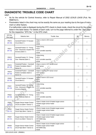
  • 1. DI1L4−17 − DIAGNOSTICS ENGINE DI−15 190 Author: Date: 2003 LEXUS LS430 (RM988U) DIAGNOSTIC TROUBLE CODE CHART HINT: S As for the vehicle for Central America, refer to Repair Manual of 2002 LEXUS LS430 (Pub. No. RM874U1). S Parameters listed in the chart may not be exactly the same as your reading due to the type of instru- ment or other factors. If a malfunction code is displayed during the DTC check in check mode, check the circuit for the codes listed in the table below. For details of each code, turn to the page referred to under the ’’See page’’ for the respective ’’DTC No.’’ in the DTC chart. DTC No. (See page) Detection Item Trouble Area MIL*1 Memory P0010 (DI−28) Camshaft Position ”A” Actuator Circuit (Bank 1) S Open or short in OCV circuit S OCV S ECM f f P0011 (DI−32) Camshaft Position ”A” −Timing Over− Advanced or System Per- formance (Bank 1) S Valve timing S OCV S VVT controller assembly S ECM f f P0012 (DI−32) Camshaft Position ”A” −Timing Over− Retarded (Bank 1) S Valve timing S OCV S VVT controller assembly S ECM f f P0016 (DI−39) Crankshaft Position − Camshaft Position Correlation (Bank 1 Sensor A) S Open or short in VVT sensor circuit S VVT sensor S ECM f f P0018 (DI−39) Crankshaft Position − Camshaft Position Correlation (Bank 2 Sensor A) S Open or short in VVT sensor circuit S VVT sensor S ECM f f P0020 (DI−28) Camshaft Position ”A” Actuator Circuit (Bank 2) S Open or short in OCV circuit S OCV S ECM f f P0021 (DI−32) Camshaft Position ”A” −Timing Over− Advanced or System Per- formance (Bank 2) S Valve timing S OCV S VVT controller assembly S ECM f f P0022 (DI−32) Camshaft Position ”A” −Timing Over− Retarded (Bank 2) S Valve timing S OCV S VVT controller assembly S ECM f f P0031 (DI−41) Oxygen Sensor Heater Control Circuit Low (Bank 1 Sensor 1) S Open in heater circuit of heated oxygen sensor S Heated oxygen sensor heater S ECM f f P0032 (DI−41) Oxygen Sensor Heater Control Circuit High (Bank 1 Sensor 1) S Short in heater circuit of heated oxygen sensor S Heated oxygen sensor heater S ECM f f P0037 (DI−41) Oxygen Sensor Heater Control Circuit Low (Bank 1 Sensor 2) S Open in heater circuit of heated oxygen sensor S Heated oxygen sensor heater S EFI MAIN relay S ECM f f P0038 (DI−41) Oxygen Sensor Heater Control Circuit High (Bank 1 Sensor 2) S Short in heater circuit of heated oxygen sensor S Heated oxygen sensor heater S EFI MAIN relay S ECM f f 2 0 0 1 - 2 0 0 3 D i a g n o s t i c T r o u b l e C o d e C h a r t
  • 2. DI−16 − DIAGNOSTICS ENGINE 191 Author: Date: 2003 LEXUS LS430 (RM988U) P0051 (DI−41) Oxygen Sensor Heater Control Circuit Low (Bank 2 Sensor 1) S Open in heater circuit of heated oxygen sensor S Heated oxygen sensor heater S ECM f f P0052 (DI−41) Oxygen Sensor Heater Control Circuit High (Bank 2 Sensor 1) S Short in heater circuit of heated oxygen sensor S Heated oxygen sensor heater S ECM f f P0057 (DI−41) Oxygen Sensor Heater Control Circuit Low (Bank 2 Sensor 2) S Open in heater circuit of heated oxygen sensor S Heated oxygen sensor heater S ECM f f P0058 (DI−41) Oxygen Sensor Heater Control Circuit High (Bank 2 Sensor 2) S Short in heater circuit of heated oxygen sensor S Heated oxygen sensor heater S ECM f f P0100 (DI−47) Mass or Volume Air Flow Circuit S Open or short in mass air flow meter circuit S Mass air flow meter S ECM f f P0101 (DI−52) Mass or Volume Air Flow Circuit Range/Performance Problem S Mass air flow meter f f P0102 (DI−47) Mass or Volume Air Flow Circuit Low Input S Open or short in mass air flow meter circuit S Mass air flow meter S ECM f f P0103 (DI−47) Mass or Volume Air Flow Circuit High Input S Open in mass air flow meter circuit (EVG circuit) S Short in mass air flow meter circuit (+B circuit) S Mass air flow meter S ECM f f P0110 (DI−53) Intake Air Temperature Circuit S Open or short in intake air temp. sensor circuit S Intake air temp. sensor (built in mass air flow meter) S ECM f f P0112 (DI−53) Intake Air Temperature Circuit Low Input S Short in intake air temp. sensor circuit S Intake air temp. sensor (built in mass air flow meter) S ECM f f P0113 (DI−53) Intake Air Temperature Circuit High Input S Open in intake air temp. sensor circuit S Intake air temp. sensor (built in mass air flow meter) S ECM f f P0115 (DI−58) Engine Coolant Temperature Cir- cuit S Open or short in engine coolant temp. sensor circuit S Engine coolant temp. sensor S ECM f f P0116 (DI−62) Engine Coolant Temperature Cir- cuit Range/Performance Prob- lem S Cooling system S Engine coolant temp. sensor f f P0117 (DI−58) Engine Coolant Temperature Cir- cuit Low Input S Short in engine coolant temp. sensor circuit S Engine coolant temp. sensor S ECM f f P0118 (DI−58) Engine Coolant Temperature Cir- cuit High Input S Open or short in engine coolant temp. sensor circuit S Engine coolant temp. sensor S ECM f f P0120 (DI−64) Throttle Pedal Position Sensor/ Switch ”A” Circuit S Open or short in throttle position sensor circuit S Throttle position sensor S ECM f f P0121 (DI−69) Throttle/Pedal Position Sensor/ Switch ”A” Circuit Range/Perfor- mance Problem S Throttle position sensor f f P0122 (DI−64) Throttle/Pedal Position Sensor/ Switch ”A” Circuit Low Input S Open in throttle position sensor circuit S Throttle position sensor S ECM f f 2 0 0 1 - 2 0 0 3 D i a g n o s t i c T r o u b l e C o d e C h a r t
  • 3. − DIAGNOSTICS ENGINE DI−17 192 Author: Date: 2003 LEXUS LS430 (RM988U) P0123 (DI−64) Throttle/Pedal Position Sensor/ Switch ”A” Circuit High Input S Short in throttle position sensor circuit S Throttle position sensor S ECM f f P0125 (DI−62) Insufficient Coolant Temperature for Closed Loop Fuel Control S Cooling system S Engine coolant temp. sensor f f P0128 (DI−70) Coolant Thermostat (Coolant Temperature Below Thermostat Regulating Temperature) S Thermostat S Cooling system S Engine coolant temp. sensor S ECM f f P0130 (DI−71) Oxygen Sensor Circuit (Bank 1 Sensor 1) S Open or short in heated oxygen sensor circuit (Bank 1 Sensor 1) S Heated oxygen sensor (Bank 1 Sensor 1) S Air induction system S Fuel pressure S Injector S ECM f f P0133 (DI−75) Oxygen Sensor Circuit Slow Re- sponse (Bank 1 Sensor 1) S Open or short in heated oxygen sensor circuit (Bank 1 Sensor 1) S Heated oxygen sensor (Bank 1 Sensor 1) S Air induction system S Fuel pressure S Injector S ECM f f P0134 (DI−78) Oxygen Sensor Circuit No Activ- ity Detected (Bank 1 Sensor 1) S Open or short in heated oxygen sensor circuit (Bank 1 Sensor 1) S Heated oxygen sensor (Bank 1 Sensor 1) S Air induction system S Fuel pressure S Injector S Gas leakage on exhaust system S PCV piping S ECM f f P0136 (DI−82) Oxygen Sensor Circuit Malfunc- tion (Bank 1 Sensor 2) S Open or short in heated oxygen sensor circuit (Bank 1 Sensor 2) S Heated oxygen sensor (Bank 1 Sensor 2) f f P0150 (DI−71) Oxygen Sensor Circuit (Bank 2 Sensor 1) S Open or short in heated oxygen sensor circuit (Bank 2 Sensor 1) S Heated oxygen sensor (Bank 2 Sensor 1) S Air induction system S Fuel pressure S Injector S ECM f f P0153 (DI−75) Oxygen Sensor Circuit Slow Re- sponse (Bank 2 Sensor 1) S Open or short in heated oxygen sensor circuit (Bank 2 Sensor 1) S Heated oxygen sensor (Bank 2 Sensor 1) S Air induction system S Fuel pressure S Injector S ECM f f 2 0 0 1 - 2 0 0 3 D i a g n o s t i c T r o u b l e C o d e C h a r t
  • 4. DI−18 − DIAGNOSTICS ENGINE 193 Author: Date: 2003 LEXUS LS430 (RM988U) P0154 (DI−78) Oxygen Sensor Circuit No Activ- ity Detected S Open or short in heated oxygen sensor circuit (Bank 2 Sensor 1) S Heated oxygen sensor (Bank 2 Sensor 1) S Air induction system S Fuel pressure S Injector S Gas leakage on exhaust system S PCV piping S ECM f f P0156 (DI−82) Oxygen Sensor Circuit Malfunc- tion (Bank 2 Sensor 2) S Open or short in heated oxygen sensor circuit (Bank 2 Sensor 2) S Heated oxygen sensor (Bank 2 Sensor 2) f f P0171 (DI−84) System too Lean (Bank 1) S Air induction system S Injector blockage S Mass air flow meter S Engine coolant temp. sensor S Fuel pressure S Gas leakage on exhaust system S Open or short in heated oxygen sensor (Bank 1 sensor 1) circuit S Heated oxygen sensor (Bank 1 sensor 1) S PCV piping S ECM f f P0172 (DI−84) System too Rich (Bank 1) S Injector leak, blockage S Mass air flow meter S Engine coolant temp. sensor S Ignition system S Fuel pressure S Gas leakage on exhaust system S Open or short in heated oxygen sensor (Bank 1 sensor 1) circuit S Heated oxygen sensor (Bank 1 sensor 1) S ECM f f P0174 (DI−84) System too Lean (Bank 2) S Air induction system S Injector blockage S Mass air flow meter S Engine coolant temp. sensor S Fuel pressure S Gas leakage on exhaust system S Open or short in heated oxygen sensor (Bank 2 sensor 1) circuit S Heated oxygen sensor (Bank 2 sensor 1) S PCV piping S ECM f f P0175 (DI−84) System too Rich (Bank 2) S Injector leak, blockage S Mass air flow meter S Engine coolant temp. sensor S Ignition system S Fuel pressure S Gas leakage in exhaust system S Open or short in heated oxygen sensor (Bank 2 sensor 1) circuit S Heated oxygen sensor (Bank 2 sensor 1) S ECM f f P0220 (DI−64) Throttle/Pedal Position Sensor/ Switch ”B” Circuit S Open or short in throttle position sensor circuit S Throttle position sensor S ECM f f 2 0 0 1 - 2 0 0 3 D i a g n o s t i c T r o u b l e C o d e C h a r t
  • 5. − DIAGNOSTICS ENGINE DI−19 194 Author: Date: 2003 LEXUS LS430 (RM988U) P0222 (DI−64) Throttle/Pedal Position Sensor/ Switch ”B” Circuit Low Input S Open in throttle position sensor circuit S Throttle position sensor S ECM f f P0223 (DI−64) Throttle/Pedal Position Sensor/ Switch ”B” Circuit High Input S Short in throttle position sensor circuit S Throttle position sensor S ECM f f P0230 (DI−89) Fuel Pump Primary Circuit S Open or short in fuel pump relay circuit S Fuel pump relay S ECM − f P0300 (DI−92) Random/Multiple Cylinder Misfire Detected S Open or short in engine wire S Connector connection S Vacuum hose connection S Ignition system S Injector S Fuel pressure S Mass air flow meter S Engine coolant temp. sensor S Compression pressure S Valve clearance S Valve timing S PCV piping S ECM f*2 f P0301 (DI−92) Cylinder 1 Misfire Detected f*2 f P0302 (DI−92) Cylinder 2 Misfire Detected f*2 f P0303 (DI−92) Cylinder 3 Misfire Detected f*2 f P0304 (DI−92) Cylinder 4 Misfire Detected f*2 f P0305 (DI−92) Cylinder 5 Misfire Detected f*2 f P0306 (DI−92) Cylinder 6 Misfire Detected f*2 f P0307 (DI−92) Cylinder 7 Misfire Detected f*2 f P0308 (DI−92) Cylinder 8 Misfire Detected f*2 f P0325 (DI−102) Knock Sensor 1 Circuit (Bank 1 or Single Sensor) S Open or short in knock sensor 1 circuit S Knock sensor 1 (looseness) S ECM f f P0330 (DI−102) Knock Sensor 2 Circuit (Bank 2) S Open or short in knock sensor 2 circuit S Knock sensor 2 (looseness) S ECM f f P0335 (DI−106) Crankshaft Position Sensor ”A” Circuit S Open or short in crankshaft position sensor circuit S Crankshaft position sensor S Signal plate (Timing belt guide) S ECM f f P0339 (DI−108) Crankshaft Position Sensor ”A” Circuit Intermittent S Open or short in crankshaft position sensor circuit S Crankshaft position sensor S Signal plate (Timing belt guide) S ECM − f P0340 (DI−109) Camshaft Position Sensor ”A” Circuit (Bank 1 or Single Sensor) S Open or short in camshaft position sensor circuit S VVT sensor S ECM f f P0341 (DI−109) Camshaft Position Sensor ”A” Circuit Range/Performance (Bank 1 or Single Sensor) f f P0345 (DI−109) Camshaft Position Sensor ”A” Circuit (Bank 2) S Open or short in camshaft position sensor circuit S VVT sensor S ECM f f P0346 (DI−109) Camshaft Position Sensor ”A” Circuit Range/Performance (Bank 2) f f 2 0 0 1 - 2 0 0 3 D i a g n o s t i c T r o u b l e C o d e C h a r t
  • 6. DI−20 − DIAGNOSTICS ENGINE 195 Author: Date: 2003 LEXUS LS430 (RM988U) P0351 (DI−112) Ignition Coil ”A” Primary/Second- ary Circuit S Open or short in IF1L and IGT1 circuit from No. 1 ignition coil with igniter to ECM S No. 1 ignition coil with igniter S Ignition system S ECM f f P0352 (DI−112) Ignition Coil ”B” Primary/Second- ary Circuit S Open or short in IF2R and IGT2 circuit from No. 2 ignition coil with igniter to ECM S No. 2 ignition coil with igniter S Ignition system S ECM f f P0353 (DI−112) Ignition Coil ”C” Primary/Second- ary Circuit S Open or short in IF2L and IGT3 circuit from No. 3 ignition coil with igniter to ECM S No. 3 ignition coil with igniter S Ignition system S ECM f f P0354 (DI−112) Ignition Coil ”D” Primary/Second- ary Circuit S Open or short in IF1R and IGT4 circuit from No. 4 ignition coil with igniter to ECM S No. 4 ignition coil with igniter S Ignition system S ECM f f P0355 (DI−112) Ignition Coil ”E” Primary/Second- ary Circuit S Open or short in IF2L and IGT5 circuit from No. 5 ignition coil with igniter to ECM S No. 5 ignition coil with igniter S Ignition system S ECM f f P0356 (DI−112) Ignition Coil ”F” Primary/Second- ary Circuit S Open or short in IF1R and IGT6 circuit from No. 6 ignition coil with igniter to ECM S No. 6 ignition coil with igniter S Ignition system S ECM f f P0357 (DI−112) Ignition Coil ”G” Primary/Second- ary Circuit S Open or short in IF1L and IGT7 circuit from No. 7 ignition coil with igniter to ECM S No. 7 ignition coil with igniter S Ignition system S ECM f f P0358 (DI−112) Ignition Coil ”H” Primary/Second- ary Circuit S Open or short in IF2R and IGT8 circuit from No. 8 ignition coil with igniter to ECM S No. 8 ignition coil with igniter S Ignition system S ECM f f P0420 (DI−119) Catalyst System Efficiency Be- low Threshold (Bank 1) S Gas leakage on exhaust system S Heated oxygen sensor (bank 1 sensor 1, 2) S Three−way catalytic converter f f P0430 (DI−119) Catalyst System Efficiency Be- low Threshold (Bank 2) S Gas leakage on exhaust system S Heated oxygen sensor (bank 2 sensor 1, 2) S Three−way catalytic converter f f 2 0 0 1 - 2 0 0 3 D i a g n o s t i c T r o u b l e C o d e C h a r t
  • 7. − DIAGNOSTICS ENGINE DI−21 196 Author: Date: 2003 LEXUS LS430 (RM988U) P0441 (DI−122) Evaporative Emission Control System Incorrect Purge Flow S Vacuum hose cracks, holed, blocked, damaged or discon- nected ((1), (2), (3), (4), (5), (6), (7), (8), (9), (10) and (11) in Fig. 1) S Fuel tank cap incorrectly installed S Fuel tank cap cracked or damaged S Open or short in vapor pressure sensor circuit S Vapor pressure sensor S Open or short in VSV circuit for EVAP S VSV for EVAP S Open or short in VSV circuit for CCV S VSV for CCV S Open or short in VSV circuit for pressure switching valve S VSV for pressure switching valve S Fuel tank cracked, holed or damaged S Charcoal canister cracked, holed or damaged S Fuel tank over fill check valve cracked or damaged S ECM f f P0442 (DI−156) Evaporative Emission Control System Leak Detected (Small Leak) S Hose or tube cracked, holed, damaged or loose seal ((3) or (9) in Fig. 1) S Fuel tank cap incorrectly installed S Fuel tank cap cracked or damaged S Vacuum hose cracked, holed, blocked, damaged or discon- nected ((1), (2), (4), (5), (6), (7), (8), (10) and (11) in Fig. 1) S Fuel tank cracked, holed or damaged S Charcoal canister cracked, holed or damaged S Open or short in vapor pressure sensor circuit S Vapor pressure sensor S Fuel tank over fill check valve cracked or damaged S ECM f f P0446 (DI−122) Evaporative Emission Control System Vent Control Circuit S Same as DTC No. P0441 f f P0451 (DI−178) Evaporative Emission Control System Pressure Sensor/Switch Range/Performance S Open or short in vapor pressure sensor circuit S Vapor pressure sensor S ECM f f P0452 (DI−178) Evaporative Emission Control System Pressure Sensor/Switch Low Input S Short in vapor pressure sensor circuit S Vapor pressure sensor S ECM f f P0453 (DI−178) Evaporative Emission Control System Pressure Sensor/Switch High Input S Open in vapor pressure sensor circuit S Vapor pressure sensor S ECM f f P0456 (DI−156) Evaporative Emission Control System Leak Detected (Very Small Leak) S Same as DTC No. P0442 f f P0500 (DI−181) Vehicle Speed Sensor ”A” S Combination meter S Open or short in vehicle speed sensor circuit S Vehicle speed sensor S ECM f f P0503 (DI−181) Vehicle Speed Sensor ”A” Inter- mittent/Erratic/High S Combination meter S Open or short in vehicle speed sensor circuit S Vehicle speed sensor S ECM − f P0504 (DI−184) Brake Switch ”A”/”B” Correlation S Stop light switch signal circuit S Stop light switch S ECM − f 2 0 0 1 - 2 0 0 3 D i a g n o s t i c T r o u b l e C o d e C h a r t
  • 8. DI−22 − DIAGNOSTICS ENGINE 197 Author: Date: 2003 LEXUS LS430 (RM988U) P0505 (DI−187) Idle Air Control System S Air induction system S Electric throttle control system S Electric throttle control system circuit S PCV piping S ECM f f P0513 (DI−189) Incorrect Immobilizer Key S Key − f P0560 (DI−190) System Voltage S Open in back−up power source circuit S EFI No.1 fuse S ECM f f P0604 (DI−192) Internal Control Module Random Access Memory (RAM) Error S ECM f f P0606 (DI−192) ECM/PCM Processor S ECM f f P0607 (DI−192) Control Module Performance S ECM f f P0617 (DI−193) Starter Relay Circuit High S Park/neutral position switch S Starter relay circuit S Ignition switch S ECM f f P0657 (DI−192) Actuator Supply Voltage Circuit / Open S ECM f f P1340 (DI−199) Camshaft Position Sensor ”A” Circuit (Bank 1 Sensor 2) S Open or short in camshaft position sensor circuit S Camshaft position sensor S LH camshaft timing pulley S ECM f f P1341 (DI−199) Camshaft Position Sensor ”A” Circuit Range/Performance (Bank 1 Sensor 2) f f P1645 (DI−201) Body ECU Malfunction S Body ECU S A/C ECU S Communication bus f − P2102 (DI−202) Throttle Actuator Control Motor Circuit Low S Open in throttle control motor circuit S Throttle control motor S ECM f f P2103 (DI−202) Throttle Actuator Control Motor Circuit High S Short in throttle control motor circuit S Throttle control motor S ECM f f P2111 (DI−206) Throttle Actuator Control System − Stuck Open S Throttle control motor S Throttle body f f P2112 (DI−206) Throttle Actuator Control System − Stuck Closed S Throttle control motor S Throttle body f f P2118 (DI−208) Throttle Actuator Control Motor Current Range/Performance S Open in ETCS power source circuit S ECM f f P2119 (DI−210) Throttle Actuator Control Throttle Body Range/Performance S Electric throttle control system S ECM f f P2120 (DI−212) Throttle/Pedal Position Sensor/ Switch ”D” Circuit S Open or short in accelerator pedal position sensor circuit S Accelerator pedal position sensor S ECM f f P2121 (DI−216) Throttle/Pedal Position Sensor/ Switch ”D” Circuit Range/Perfor- mance S Accelerator pedal position sensor f f P2122 (DI−212) Throttle/Pedal Position Sensor/ Switch ”D” Circuit Low Input S Open in accelerator pedal position sensor circuit S Accelerator pedal position sensor S ECM f f 2 0 0 1 - 2 0 0 3 D i a g n o s t i c T r o u b l e C o d e C h a r t
  • 9. − DIAGNOSTICS ENGINE DI−23 198 Author: Date: 2003 LEXUS LS430 (RM988U) P2123 (DI−212) Throttle/Pedal Position Sensor/ Switch ”D” Circuit High Input S Short in accelerator pedal position sensor circuit S Accelerator pedal position sensor S ECM f f P2125 (DI−212) Throttle/Pedal Position Sensor/ Switch ”E” Circuit S Short in accelerator pedal position sensor circuit S Accelerator pedal position sensor S ECM f f P2127 (DI−212) Throttle/Pedal Position Sensor/ Switch ”E” Circuit Low Input S Short in accelerator pedal position sensor circuit S Accelerator pedal position sensor S ECM f f P2128 (DI−212) Throttle/Pedal Position Sensor/ Switch ”E” Circuit High Input S Short in accelerator pedal position sensor circuit S Accelerator pedal position sensor S ECM f f P2135 (DI−64) Throttle Pedal Position Sensor/ Switch ”A” / ”B” Voltage Correla- tion S VTA1 and VTA2 circuit are short−circuited S Throttle position sensor S ECM f f P2138 (DI−212) Throttle/Pedal Position Sensor/ Switch ”D”/”E” Voltage Correla- tion S Short in accelerator pedal position sensor circuit S Accelerator pedal position sensor S ECM f f P2195 (DI−71) Oxygen Sensor Signal Stuck Lean (Bank 1 Sensor 1) S Open or short in heated oxygen sensor circuit (Bank 1, 2 Sen- sor 1) S Heated oxygen sensor (Bank 1, 2 Sensor 1) S EFI MAIN relay S Air induction system S Fuel pressure S Injector S ECM f f P2196 (DI−71) Oxygen Sensor Signal Stuck Rich (Bank 1 Sensor 1) f f P2197 (DI−71) Oxygen Sensor Signal Stuck Lean (Bank 2 Sensor 1) f f P2198 (DI−71) Oxygen Sensor Signal Stuck Rich (Bank 2 Sensor 1) f f *1: MIL lights up. *2: MIL lights up or blinks. *: − .... MIL does not light up, f .... MIL lights up 2 0 0 1 - 2 0 0 3 D i a g n o s t i c T r o u b l e C o d e C h a r t
  • 10. DI8E9−04 DI−248 − DIAGNOSTICS AUTOMATIC TRANSMISSION 423 Author: Date: 2003 LEXUS LS430 (RM988U) DIAGNOSTIC TROUBLE CODE CHART HINT: S As for the vehicle for Central America, refer to Repair Manual of 2002 LEXUS LS430 (Pub. No. RM874U1). S If a DTC is displayed during the DTC check, check the circuit listed in the table below and proceed to the page given. * : F...MIL light up DTC No. (See Page) Detection Item Trouble Area MIL* Memory P0500 (DI−258) Vehicle Speed Sensor ”A” S Open or short in vehicle speed sensor (SP2) circuit S Speed sensor (SP2) S ECM S Automatic transmission assembly F f P0705 (DI−261) Transmission Range Sensor Cir- cuit Malfunction (PRNDL Input) S Short in park/neutral position switch circuit S Park/neutral position switch S ECM F f P0710 (DI−265) Transmission Fluid Temperature Sensor ”A” Circuit S Open or short in ATF temperature sensor circuit S ATF temperature sensor S ECM F f P0711 (DI−268) Transmission Fluid Temperature Sensor ”A” Performance F f P0712 (DI−265) Transmission Fluid Temperature Sensor ”A” Circuit Low Input F f P0713 (DI−265) Transmission Fluid Temperature Sensor ”A” Circuit High Input F f P0717 (DI−270) Input Speed Sensor Circuit No Signal S Open or short in speed sensor (NC0) circuit S Speed sensor (NC0) S ECM S Automatic transmission assembly F f P0724 (DI−273) Brake Switch ”B” Circuit High S Open or short in stop light switch signal circuit S Stop light switch S ECM F f P0751 (DI−274) Shift Solenoid ”A” Performance (Shift Solenoid Valve S1) S Shift solenoid valve No. 1 is stuck open or closed S Valve body is blocked up or stuck S Automatic transmission assembly F f P0756 (DI−274) Shift Solenoid ”B” Performance (Shift Solenoid Valve S2) S Shift solenoid valve No. 2 is stuck open or closed S Valve body is blocked up or stuck S Automatic transmission assembly F f P0761 (DI−274) Shift Solenoid ”C” Performance (Shift Solenoid Valve S3) S Shift solenoid valve No. 3 is stuck open or closed S Valve body is blocked up or stuck S Automatic transmission assembly F f P0973 (DI−277) Shift Solenoid ”A” Control Circuit Low (Shift Solenoid Valve S1) S Open or short in shift solenoid valve No. 1 circuit S Shift solenoid valve No. 1 S ECM F f P0974 (DI−277) Shift Solenoid ”A” Control Circuit High (Shift Solenoid Valve S1) F f P0976 (DI−277) Shift Solenoid ”B” Control Circuit Low (Shift Solenoid Valve S2) S Open or short in shift solenoid valve No. 2 circuit S Shift solenoid valve No. 2 S ECM F f P0977 (DI−277) Shift Solenoid ”B” Control Circuit High (Shift Solenoid Valve S2) F f P0979 (DI−277) Shift Solenoid ”C” Control Circuit Low (Shift Solenoid Valve S3) S Open or short in shift solenoid valve No. 3 circuit S Shift solenoid valve No. 3 S ECM F f P0980 (DI−277) Shift Solenoid ”C” Control Circuit High (Shift Solenoid Valve S3) F f 2 0 0 1 - 2 0 0 3 D i a g n o s t i c T r o u b l e C o d e C h a r t
  • 11. − DIAGNOSTICS AUTOMATIC TRANSMISSION DI−249 424 Author: Date: 2003 LEXUS LS430 (RM988U) P0982 (DI−283) Shift Solenoid ”D” Control Circuit Low (Shift Solenoid Valve S4) S Open or short in shift solenoid valve No. 4 circuit S Shift solenoid valve No. 4 S ECM F f P0983 (DI−283) Shift Solenoid ”D” Control Circuit High (Shift Solenoid Valve S4) F f P2716 (DI−286) Pressure Control Solenoid ”D” Electrical (Shift Solenoid Valve SLT) S Open or short in shift solenoid valve SLT circuit S Shift solenoid valve SLT S ECM F f P2725 (DI−290) Pressure Control Solenoid ”E” Electrical (Shift Solenoid Valve SLN) S Open or short in shift solenoid valve SLN circuit S Shift solenoid valve SLN S ECM F f P2757 (DI−294) Torque Converter Clutch Pres- sure Control Solenoid Perfor- mance (Shift Solenoid Valve SLU) S Shift solenoid valve SLU is stuck open or closed S Valve body is blocked up or stuck S Lock−up clutch S Automatic transmission assembly F f P2759 (DI−296) Torque Converter Clutch Pres- sure Control Solenoid Control Circuit Electrical (Shift Solenoid Valve SLU) S Open or short in shift solenoid valve SLU circuit S Shift solenoid valve SLU S ECM F f HINT: This DTC may be output when the clutch, brake and gear components etc. inside the automatic transmission are damaged. 2 0 0 1 - 2 0 0 3 D i a g n o s t i c T r o u b l e C o d e C h a r t
  • 12. DI0VS−07 DI−310 − DIAGNOSTICS ELECTRONIC MODULATED AIR SUSPENSION 485 Author: Date: 2003 LEXUS LS430 (RM988U) DIAGNOSTIC TROUBLE CODE CHART HINT: S Using SST 09843−18040, connect terminals Tc and CG of the DLC3. S If any abnormality is not found when the parts are inspected, inspect the suspension control ECU. S If a malfunction code is displayed during the DTC check, check the circuit listed for that code. For de- tails of each code, turn to the page mentioned below ”DTC No.” in the DTC chart. DTC No. (See Page) Detection Item Trouble Area Indicator Light*1 ( )*2 Memory*3 C1711 / 11 (DI−318) Open or short circuit in right front height control sensor circuit S Right front, left front, right rear, left rear height control sensors S Each height control sensor circuit f (f) f C1712 / 12 (DI−318) Open or short circuit in left front height control sensor circuit f (f) f C1713 / 13 (DI−318) Open or short circuit in right rear height control sensor circuit f (f) f C1714 / 14 (DI−318) Open or short circuit in left rear height control sensor circuit f (f) f C1715 / 15 (DI−323) Open or short circuit in right front acceleration sensor circuit S Right front, left front, rear acceleration sensors S Each acceleration sensor circuit f (−) f C1716 / 16 (DI−323) Open or short circuit in left front acceleration sensor circuit f (−) f C1717 / 17 (DI−323) Open or short circuit in rear acceleration sensor circuit f (−) f C1725 / 21 (DI−328) Open or short circuit in right front suspension control actuator circuit S Right front, left front, right rear, left rear suspension control actuators S Each suspension control actuator circuit f (−) f C1726 / 22 (DI−328) Open or short circuit in left front suspension control actuator circuit f (−) f C1727 / 23 (DI−328) Open or short circuit in right rear suspension control actuator circuit f (−) f C1728 / 24 (DI−328) Open or short circuit in left rear suspension control actuator circuit f (−) f C1737 / 31 (DI−334) Open or short circuit in right front height control solenoid valve circuit S Right front, left front, right rear, left rear height control solenoid valves S Each height control solenoid valve circuit f (f) f C1739 / 32 (DI−334) Open or short circuit in left front height control solenoid valve circuit f (f) f C1739 / 33 (DI−334) Open or short circuit in right rear height control solenoid valve circuit f (f) f C1740 / 34 (DI−334) Open or short circuit in left rear height control solenoid valve circuit f (f) f C1735 / 35 (DI−334) Open or short circuit in height control exhaust valve circuit S Height control exhaust valve S Height control exhaust valve circuit f (f) f C1741 / 41 (DI−341) Open or short circuit in AIR SUS relay circuit S AIR SUS relay S AIR SUS relay circuit f (f) f C1742 / 42 (DI−346) Lock, open or short circuit in height control compressor circuit S Height control compressor S Height control compressor circuit f (f) f 2 0 0 1 - 2 0 0 3 D i a g n o s t i c T r o u b l e C o d e C h a r t
  • 13. − DIAGNOSTICS ELECTRONIC MODULATED AIR SUSPENSION DI−311 486 Author: Date: 2003 LEXUS LS430 (RM988U) C1751 / 51*4 (DI−352) Continuous electric current to height control compressor circuit S Height control compressor S Height control compressor circuit S Height control sensor link S Height control sensor S Relief valve S Height control relay comes off S Air leakage from the air tube or each valve S Clogging in the air tube or each valve f (−) f C1752 / 52*5 (DI−354) Continuous electric current to height control exhaust valve S Height control link S Height control sensor S Clogging in the air tube or each valve f (−) f C1774 / 74 (DI−355) Power voltage drop S Battery S Power source circuit f (−) − C1776 / 76 (DI−360) Vehicle speed sensor circuit malfunction S ABS speed sensor S Vehicle speed sensor circuit S Skid control ECU f (−) f C1777 / 77 (DI−362) Open or short circuit in steering angle sensor circuit S Steering angle sensor S Steering angle sensor circuit f (−) f C1778 / 78 (DI−365) Open or short circuit in chassis ECU (skid control ECU) commu- nication circuit malfunction S Skid control ECU S Chassis ECU communication circuit f (−) − C1779 / 79 (DI−367) Engine revolution signal circuit malfunction S Crankshaft position sensor S Crankshaft position sensor circuit S ECM f (−) f *1: For codes in the ”Indicator Light” column with a ”f” mark, the absorber control indicator light blinks at 1 second intervals. *2: When a trouble occurs, ”HEIGHT HI” is displayed in the multi−information. Also, the master warning light is lit on the combination meter and an alarm sounds. *3: Codes with the ”f” mark in the ”Memory” column are stored in memory even when the ignition switch is OFF. For codes with the ”−” mark, it does not memory. *4: Since the relief pressure of the compressed air is 980 kPa (10 kgf/cm2, 142 psi), if the vehicle height con- trol is attempted on a steeply sloping road, when the vehicle is overloaded, or when the vehicle height is jacked up with the engine running, code ”C1751 / 51” may be output and vehicle height control may be sus- pended. (This is not abnormal.) In this case, however, when detecting the first error, approx. 10 minutes after the ignition switch was turned ON, vehicle height control is resumed. When the following errors are detected, it takes 70 minutes until the control is resumed. *5: If vehicle height control is operated while the wheels are removed or the vehicle is jacked up, code ”C1752 / 52” may be output, but this is not abnormal. When code ”C1752 / 52” is output, the vehicle height control is not carried out. However, the control is resumed if the ignition switch is turned OFF, then ON again. 2 0 0 1 - 2 0 0 3 D i a g n o s t i c T r o u b l e C o d e C h a r t
  • 14. DI0WA−13 DI−402 − DIAGNOSTICS ABS WITH EBD BA TRAC VSC SYSTEM AND PROGRESSIVE POWER STEERING 577 Author: Date: 2003 LEXUS LS430 (RM988U) DIAGNOSTIC TROUBLE CODE CHART NOTICE: Before replacing or removing the part, turn the ignition switch OFF. HINT: S Using SST 09843−18040, connect the terminals Tc and CG of DLC3. S If any abnormality is not found on inspected parts, inspect the ECU. S If a malfunction code is displayed during the DTC check, check the circuit indicated by DTC. For details of each code, turn to the pages in the ”See page” for respective ”DTC No.” in the DTC chart. DTC chart of ABS: DTC No. (See Page) Detection Item Trouble Area C0200 / 31*1 (DI−411) Right front wheel speed sensor signal malfunction S Right front, left front, right rear, left rear speed sensor S Each speed sensor circuit S Sensor rotor C0205 / 32*1 (DI−411) Left front wheel speed sensor signal malfunction C0210 / 33*1 (DI−411) Right rear wheel speed sensor signal malfunction C0215 / 34*1 (DI−411) Left rear wheel speed sensor signal malfunction C0226 / 21 (DI−418) Open or short circuit in brake actuator solenoid circuit (SFR circuit) S Brake actuator S SFRH or SFRR circuit C0236 / 22 (DI−418) Open or short circuit in brake actuator solenoid circuit (SFL circuit) S Brake actuator S SFLH or SFLR circuit C0246 / 23 (DI−418) Open or short circuit in brake actuator solenoid circuit (SRR circuit) S Brake actuator S SRRH or SRRR circuit C0256 / 24 (DI−418) Open or short circuit in brake actuator solenoid circuit (SRL circuit) S Brake actuator S SRLH or SRLR circuit C0273 / 13*1 (DI−420) Open circuit in ABS MTR relay circuit S ABS MTR relay S ABS MTR relay circuit C0274 / 14 (DI−420) Short circuit in ABS MTR relay circuit C0278 / 11 (DI−424) Open circuit in ABS SOL relay circuit S ABS SOL relay S ABS SOL relay circuit C0279 / 12 (DI−424) Short circuit in ABS SOL relay circuit C1225 / 25 (DI−435) Open or short circuit in brake actuator solenoid circuit (SM circuit) S Brake actuator S SMF or SMR circuit C1226 / 26 (DI−435) Open or short circuit in brake actuator solenoid circuit (SRM circuit) S Brake actuator S SRMF or SRMR circuit C1227 / 27 (DI−435) Open or short circuit in brake actuator solenoid circuit (SRC circuit) S Brake actuator S SRCF or SRCR circuit C1235 / 35 (DI−411) Foreign matter is attached on the tip of the right front sensor S Right front, left front, right rear, left rear speed sensor S Sensor rotor C1236 / 36 (DI−411) Foreign matter is attached on the tip of the left front sensor C1238 / 38 (DI−411) Foreign matter is attached on the tip of the right rear sensor C1239 / 39 (DI−411) Foreign matter is attached on the tip of the left rear sensor 2 0 0 1 - 2 0 0 3 D i a g n o s t i c T r o u b l e C o d e C h a r t
  • 15. − DIAGNOSTICS ABS WITH EBD BA TRAC VSC SYSTEM AND PROGRESSIVE POWER STEERING DI−403 578 Author: Date: 2003 LEXUS LS430 (RM988U) C1241 / 41 (DI−445) Low battery positive voltage or abnormally high battery positive voltage S Battery S Charging system S Power source circuit C1243 / 43*1 (DI−449) Malfunction in deceleration sensor (constant output) S Deceleration sensor S Wire harness for deceleration sensor system C1244 / 44 (DI−453) Open or short circuit in deceleration sensor circuit S Deceleration sensor S Deceleration sensor circuit C1245 / 45*1 (DI−449) Malfunction in deceleration sensor S Deceleration sensor S Wire harness for deceleration sensor system C1246 / 46*2 (DI−457) Malfunction in master cylinder pressure sensor S Master cylinder pressure sensor S Master cylinder pressure sensor circuit C1249 / 49 (DI−460) Open circuit in stop light switch circuit S Stop light bulb S Stop light switch circuit C1251 / 51*1 (DI−463) ABS pump motor is locked Open circuit in pump motor circuit ABS pump motor C1267 / 67 (DI−465) Malfunction in brake pedal load sensing switch S Brake pedal load sensing switch S Brake pedal load sensing switch circuit Always ON (DI−473) Malfunction in skid control ECU S Power source circuit S ABS warning light circuit S Multiplex communication circuit S Skid control ECU *1, *2: Even after the troubled areas are repaired, ABS warning light will not go OFF unless the following operations are performed. S *1: (1) Drive the vehicle at 20 km/h (12 mph) for 30 seconds or more and check that the ABS warning light goes off. (2) Clear the DTC (See page DI−390). S *2: (1) Keep the vehicle in the stationary condition for 5 seconds or more and depress the brake pedal lightly 2 or 3 times. (2) Drive the vehicle at the vehicle speed 50 km/h (31 mph) and keep depressing the brake pedal strongly for about 3 seconds. (3) Repeat the above operation 3 times or more and check that the ABS warning light goes off. (4) Clear the DTC (See page DI−390). HINT: There is a case that LEXUS hand−held tester cannot be used when ABS warning light is always on. 2 0 0 1 - 2 0 0 3 D i a g n o s t i c T r o u b l e C o d e C h a r t
  • 16. DI−404 − DIAGNOSTICS ABS WITH EBD BA TRAC VSC SYSTEM AND PROGRESSIVE POWER STEERING 579 Author: Date: 2003 LEXUS LS430 (RM988U) DTC chart of VSC: DTC No. (See Page) Detection Item Trouble Area C1201 / 51 (DI−428) Malfunction in ECM Engine control system C1202 / 52 (DI−429) Brake fluid level low Open circuit in brake fluid level warning switch circuit S Brake fluid level S Brake fluid level warning switch S Brake fluid level warning switch circuit C1203 / 53 (DI−431) Malfunction in ECM communication circuit S TRC+ or TRC− circuit S ENG+ or ENG− circuit S ECM C1210 / 36 (DI−441) Zero point calibration of yaw rate sensor undone S Yaw rate sensor S Yaw rate sensor circuit S P position switch circuit C1224 / 44 (DI−433) Open or short circuit in NEO signal circuit S NEO circuit S ECM C1231 / 31 (DI−437) Malfunction in steering angle sensor S Steering angle sensor S Steering angle sensor circuit C1232 / 32 (DI−453) Malfunction in deceleration sensor (constant output) S Deceleration sensor S Deceleration sensor circuit C1233 / 33 (DI−441) Open or short circuit in yaw rate sensor circuit S Yaw rate sensor S Yaw rate sensor circuit C1234 / 34 (DI−441) Malfunction in yaw rate sensor C1303 / 57 (DI−468) Malfunction in multiplex communication circuit S MPX1 circuit S MPX2 circuit C1335 / 35 (DI−437) Open circuit in steering angle sensor S Steering angle sensor S Steering angle sensor circuit C1336 / 39 (DI−449) Zero point calibration of deceleration sensor undone S Deceleration sensor S Deceleration sensor circuit S P position switch circuit Always ON (DI−477) Malfunction in skid control ECU Open circuit in VSC warning indicator circuit S Power source circuit S Skid control ECU HINT: In some cases LEXUS hand−held tester cannot be used when VSC warning light is always on. DTC chart of PPS: DTC No. (See Page) Detection Item Trouble Area C1560 (DI−470) Malfunction in PPS solenoid circuit S PPS solenoid S PPS solenoid circuit C1561 (DI−470) 2 0 0 1 - 2 0 0 3 D i a g n o s t i c T r o u b l e C o d e C h a r t
  • 17. DI1T7−10 DI−504 − DIAGNOSTICS POWER TILT AND POWER TELESCOPIC STEERING COLUMN 679 Author: Date: 2003 LEXUS LS430 (RM988U) DIAGNOSTIC TROUBLE CODE CHART If a DTC is displayed during the DTC check, check the circuit for that code listed in the table below. For details of each code, turn to the page referred to under the ”See page” for the respective ”DTC No.” in the DTC chart. DTC No. (See Page) Detection Item Trouble Area B2602 (DI−508) Key unlock warning switch malfunction S Key unlock warning switch B2610 (DI−509) Tilt position sensor or tilt motor malfunction S Sensor power source circuit S Actuator power source circuit S Tilt motor circuit S Power tilt and power telescopic ECU B2611 (DI−511) Telescopic position sensor or telescopic motor malfunction S Sensor power source circuit S Actuator power source circuit S Telescopic motor circuit S Power tilt and power telescopic ECU B2620 (DI−513) ECU power source circuit malfunction S Battery S ECU power source circuit S Power tilt and power telescopic ECU B2621 (DI−515) Communication interruption S Multiplex communication system S Power tilt and power telescopic ECU 2 0 0 1 - 2 0 0 3 D i a g n o s t i c T r o u b l e C o d e C h a r t
  • 18. DI6OZ−24 − DIAGNOSTICS SUPPLEMENTAL RESTRAINT SYSTEM DI−541 716 2003 LEXUS LS430 (RM988U) DIAGNOSTIC TROUBLE CODE CHART If a malfunction code is displayed during the DTC check, check the circuit listed for that code in the table below (Proceed to the page given for that circuit.). DTC No. (See Page) Detection Item Trouble Area SRS Warning Light B0100/13 (DI−549) Short in D squib circuit S Steering wheel pad (squib) S Spiral cable S Airbag sensor assembly S Instrument panel wire ON B0101/14 (DI−554) Open in D squib circuit S Steering wheel pad (squib) S Spiral cable S Airbag sensor assembly S Instrument panel wire ON B0102/11 (DI−558) Short in D squib circuit (to ground) S Steering wheel pad (squib) S Spiral cable S Airbag sensor assembly S Instrument panel wire ON B0103/12 (DI−562) Short in D squib circuit (to B+) S Steering wheel pad (squib) S Spiral cable S Airbag sensor assembly S Instrument panel wire ON B0105/53 (DI−566) Short in P squib circuit S Front passenger airbag assembly (squib) S Airbag sensor assembly S Instrument panel wire ON B0106/54 (DI−570) Open in P squib circuit S Front passenger airbag assembly (squib) S Airbag sensor assembly S Instrument panel wire ON B0107/51 (DI−573) Short in P squib circuit (to ground) S Front passenger airbag assembly (squib) S Airbag sensor assembly S Instrument panel wire ON B0108/52 (DI−576) Short in P squib circuit (to B+) S Front passenger airbag assembly (squib) S Airbag sensor assembly S Instrument panel wire ON B0110/43 (DI−579) Short in side squib RH circuit S Side airbag assembly RH (squib) S Airbag sensor assembly S Floor wire Blink B0111/44 (DI−583) Open in side squib RH circuit S Side airbag assembly RH (squib) S Airbag sensor assembly S Floor wire Blink B0112/41 (DI−586) Short in side squib RH circuit (to ground) S Side airbag assembly RH (squib) S Airbag sensor assembly S Floor wire Blink B0113/42 (DI−589) Short in side squib RH circuit (to B+) S Side airbag assembly RH (squib) S Airbag sensor assembly S Floor wire Blink B0115/47 (DI−592) Short in side squib LH circuit S Side airbag assembly LH (squib) S Airbag sensor assembly S Floor No. 2 wire Blink B0116/48 (DI−596) Open in side squib LH circuit S Side airbag assembly LH (squib) S Airbag sensor assembly S Floor No. 2 wire Blink 2 0 0 1 - 2 0 0 3 D i a g n o s t i c T r o u b l e C o d e C h a r t
  • 19. DI−542 − DIAGNOSTICS SUPPLEMENTAL RESTRAINT SYSTEM 717 2003 LEXUS LS430 (RM988U) B0117/45 (DI−599) Short in side squib LH circuit (to ground) S Side airbag assembly LH (squib) S Airbag sensor assembly S Floor No. 2 wire Blink B0118/46 (DI−602) Short in side squib LH circuit (to B+) S Side airbag assembly LH (squib) S Airbag sensor assembly S Floor No. 2 wire Blink B0121/26 (DI−605) Seat belt buckle switch RH malfunction S Seat belt buckle switch RH S Airbag sensor assembly S Floor wire ON B0122/26 (DI−605) Seat belt buckle switch RH malfunction S Seat belt buckle switch RH S Airbag sensor assembly S Floor wire ON B0126/27 (DI−609) Seat belt buckle switch LH malfunction S Seat belt buckle switch LH S Airbag sensor assembly S Floor No. 2 wire ON B0127/27 (DI−609) Seat belt buckle switch LH malfunction S Seat belt buckle switch LH S Airbag sensor assembly S Floor No. 2 wire ON B0130/63 (DI−613) Short in front P/T squib RH circuit S Front seat belt pretensioner RH (squib) S Airbag sensor assembly S Floor wire Blink B0131/64 (DI−617) Open in front P/T squib RH circuit S Front seat belt pretensioner RH (squib) S Airbag sensor assembly S Floor wire Blink B0132/61 (DI−620) Short in front P/T squib RH circuit (to ground) S Front seat belt pretensioner RH (squib) S Airbag sensor assembly S Floor wire Blink B0133/62 (DI−623) Short in front P/T squib RH circuit (to B+) S Front seat belt pretensioner RH (squib) S Airbag sensor assembly S Floor wire Blink B0135/73 (DI−626) Short in front P/T squib LH circuit S Front seat belt pretensioner LH (squib) S Airbag sensor assembly S Floor No. 2 wire Blink B0136/74 (DI−630) Open in front P/T squib LH circuit S Front seat belt pretensioner LH (squib) S Airbag sensor assembly S Floor No. 2 wire Blink B0137/71 (DI−633) Short in front P/T squib LH circuit (to ground) S Front seat belt pretensioner LH (squib) S Airbag sensor assembly S Floor No. 2 wire Blink B0138/72 (DI−636) Short in front P/T squib LH circuit (to B+) S Front seat belt pretensioner LH (squib) S Airbag sensor assembly S Floor No. 2 wire Blink B1100/31 (DI−639) Airbag sensor assembly malfunction S Instrument Panel Wire S Engine Room Main Wire S Front Airbag Sensor LH S Front Airbag Sensor RH S Airbag Sensor Assembly ON B1135/24 (DI−641) Half connection in airbag sensor assembly connector S Airbag sensor assembly S Instrument panel wire S Floor wire S Floor No. 2 wire ON B1140/32 (DI−644) Side airbag sensor assembly RH mal- function S Side airbag sensor assembly RH S Airbag sensor assembly S Floor wire Blink 2 0 0 1 - 2 0 0 3 D i a g n o s t i c T r o u b l e C o d e C h a r t
  • 20. − DIAGNOSTICS SUPPLEMENTAL RESTRAINT SYSTEM DI−543 718 2003 LEXUS LS430 (RM988U) B1141/33 (DI−650) Side airbag sensor assembly LH mal- function S Side airbag sensor assembly LH S Airbag sensor assembly S Floor No. 2 wire Blink B1148/36 (DI−656) Front airbag sensor RH malfunction S Front airbag sensor RH S Airbag sensor assembly S Instrument panel wire S Engine room main wire ON B1149/37 (DI−663) Front airbag sensor LH malfunction S Front airbag sensor LH S Airbag sensor assembly S Instrument panel wire S Engine room main wire ON B1150/23 (DI−670) Occupant detection malfunction S Occupant detection sensor S Airbag sensor assembly S Floor wire ON B1153/25 (DI−674) Seat position sensor malfunction S Seat position sensor assembly S Airbag sensor assembly S Floor No. 2 wire ON B1154/38 (DI−680) Curtain shield airbag sensor RH mal- function S Curtain shield airbag sensor RH S Airbag sensor assembly S Floor wire Blink B1155/39 (DI−685) Curtain shield airbag sensor LH mal- function S Curtain shield airbag sensor LH S Airbag sensor assembly S Floor No. 2 wire Blink B1160/83 (DI−690) Short in curtain shield squib RH circuit S Curtain shield airbag assembly RH (squib) S Airbag sensor assembly S Floor wire Blink B1161/84 (DI−694) Open in curtain shield squib RH circuit S Curtain shield airbag assembly RH (squib) S Airbag sensor assembly S Floor wire Blink B1162/81 (DI−697) Short in curtain shield squib RH circuit (to ground) S Curtain shield airbag assembly RH (squib) S Airbag sensor assembly S Floor wire Blink B1163/82 (DI−700) Short in curtain shield squib RH circuit (to B+) S Curtain shield airbag assembly RH (squib) S Airbag sensor assembly S Floor wire Blink B1165/87 (DI−703) Short in curtain shield squib LH circuit S Curtain shield airbag assembly LH (squib) S Airbag sensor assembly S Floor No. 2 wire Blink B1166/88 (DI−707) Open in curtain shield squib LH circuit S Curtain shield airbag assembly LH (squib) S Airbag sensor assembly S Floor No. 2 wire Blink B1167/85 (DI−710) Short in curtain shield squib LH circuit (to ground) S Curtain shield airbag assembly LH (squib) S Airbag sensor assembly S Floor No. 2 wire Blink B1168/86 (DI−713) Short in curtain shield squib LH circuit (to B+) S Curtain shield airbag assembly LH (squib) S Airbag sensor assembly S Floor No. 2 wire Blink B1180/17 (DI−716) Short in D squib (2nd step) circuit S Steering wheel pad (D squib, 2nd step) S Spiral cable S Airbag sensor assembly S Instrument panel wire ON 2 0 0 1 - 2 0 0 3 D i a g n o s t i c T r o u b l e C o d e C h a r t
  • 21. DI−544 − DIAGNOSTICS SUPPLEMENTAL RESTRAINT SYSTEM 719 2003 LEXUS LS430 (RM988U) B1181/18 (DI−721) Open in D squib (2nd step) circuit S Steering wheel pad (D squib, 2nd step) S Spiral cable S Airbag sensor assembly S Instrument panel wire ON B1182/19 (DI−725) Short in D squib (2nd step) circuit (to ground) S Steering wheel pad (D squib, 2nd step) S Spiral cable S Airbag sensor assembly S Instrument panel wire ON B1183/22 (DI−729) Short in D squib (2nd step) circuit (to B+) S Steering wheel pad (D squib, 2nd step) S Spiral cable S Airbag sensor assembly S Instrument panel wire ON B1185/57 (DI−733) Short in P squib (2nd step) circuit S Front passenger airbag assembly (squib) S Airbag sensor assembly S Instrument panel wire ON B1186/58 (DI−737) Open in P squib (2nd step) circuit S Front passenger airbag assembly (squib) S Airbag sensor assembly S Instrument panel wire ON B1187/55 (DI−740) Short in P squib (2nd step) circuit (to ground) S Front passenger airbag assembly (squib) S Airbag sensor assembly S Instrument panel wire ON B1188/56 (DI−743) Short in P squib (2nd step) circuit (to B+) S Front passenger airbag assembly (squib) S Airbag sensor assembly S Instrument panel wire ON B1190/67 (DI−746) Short in rear P/T squib RH circuit S Rear seat belt pretensioner RH (squib) S Airbag sensor assembly S Floor wire Blink B1191/68 (DI−750) Open in rear P/T squib RH circuit S Rear seat belt pretensioner RH (squib) S Airbag sensor assembly S Floor wire Blink B1192/65 (DI−753) Short in rear P/T squib RH circuit (to ground) S Rear seat belt pretensioner RH (squib) S Airbag sensor assembly S Floor wire Blink B1193/66 (DI−756) Short in rear P/T squib RH circuit (to B+) S Rear seat belt pretensioner RH (squib) S Airbag sensor assembly S Floor wire Blink B1195/77 (DI−759) Short in rear P/T squib LH circuit S Rear seat belt pretensioner LH (squib) S Airbag sensor assembly S Floor No. 2 wire Blink B1196/78 (DI−763) Open in rear P/T squib LH circuit S Rear seat belt pretensioner LH (squib) S Airbag sensor assembly S Floor No. 2 wire Blink B1197/75 (DI−766) Short in rear P/T squib LH circuit (to ground) S Rear seat belt pretensioner LH (squib) S Airbag sensor assembly S Floor No. 2 wire Blink B1198/76 (DI−769) Short in rear P/T squib LH circuit (to B+) S Rear seat belt pretensioner LH (squib) S Airbag sensor assembly S Floor No. 2 wire Blink Normal (DI−772) System normal − OFF Voltage source drop S Battery S Airbag sensor assembly ON 2 0 0 1 - 2 0 0 3 D i a g n o s t i c T r o u b l e C o d e C h a r t
  • 22. − DIAGNOSTICS SUPPLEMENTAL RESTRAINT SYSTEM DI−544−1 720 2003 LEXUS LS430 (RM988U) HINT: S When the SRS warning light remains lit up and the DTC is the normal code, a voltage source drop is possible. This malfunction is not stored in memory by the airbag sensor assembly and if the power source volt- age returns to normal, the SRS warning light will automatically go out. S When 2 or more codes are indicated, smaller numbered code will be shown first. S If a code not listed on the chart is displayed, the airbag sensor assembly is at fault. S In the case of any malfunction concerning any open circuit, ground short, or B+ short due to any squib, another malfunction code may not be detected. In this case, correct the malfunction currently indicated and then perform malfunction diagnosis again. Another malfunction code may then be detected. 2 0 0 1 - 2 0 0 3 D i a g n o s t i c T r o u b l e C o d e C h a r t
  • 23. DI8U6−02 − DIAGNOSTICS THEFT DETERRENT SYSTEM DI−871 1061 Author: Date: 2003 LEXUS LS430 (RM988U) DIAGNOSTIC TROUBLE CODE CHART If a malfunction code is displayed during the DTC check, check the circuit listed for that code in the table below and proceed to the appropriate page. DTC No. (See Page) Circuit Inspection Trouble Area B1242 (DI−879) Wireless Door Lock Tuner Circuit Malfunction S Wire harness S Wireless Door Lock Tuner S Luggage Tuner S Theft deterrent ECU 2 0 0 1 - 2 0 0 3 D i a g n o s t i c T r o u b l e C o d e C h a r t
  • 24. DI8WR−02 − DIAGNOSTICS CRUISE CONTROL SYSTEM DI−899 1089 Author: Date: 2003 LEXUS LS430 (RM988U) DIAGNOSTIC TROUBLE CODE CHART If an error code is displayed during the DTC check, check the circuit listed for that code in the table below and proceed to an appropriate page. w/o Adaptive laser cruise control system DTC No. (See Page) Circuit Inspection Trouble Area P0500/ 21, P0503/ 23 (DI−911) Vehicle speed sensor circuit S Vehicle speed sensor S Wire harness or connector S ECM P0571/ 52 (DI−912) Stop light switch circuit S Stop light switch S Wire harness or connector S ECM P0607/ 54 (DI−916) Input signal circuit S ECM w/ Adaptive laser cruise control system DTC No. (See Page) Circuit Inspection Trouble Area P0500/ 21, P0503/ 23 (DI−911) Vehicle speed sensor circuit S Speed sensor S Wire harness or connector between ECM and vehicle speed sensor S Vehicle speed sensor S ECM P0571/ 52 (DI−912) Stop light switch circuit S Stop light switch S Wire harness or connector between ECM and stop light switch circuit S ECM P0607/ 54 (DI−916) Input signal circuit S ECM P1615/ 61 (DI−923) Communication error from distance control ECU to ECM S Wire harness or connector S Distance control ECU S ECM P1616/ 62 (DI−925) Communication error from ECM to distance control ECU S Wire harness or connector S ECM S Distance control ECU P1617/ 63 (DI−927) Distance control ECU malfunction S Distance control ECU P1630/ 64 (DI−932) Communication error from skid control ECU to ECM S Wire harness or connector S Skid control ECU S ECM U0100/ 65 (DI−934) Communication error from ECM to skid control ECU S Wire harness or connector S ECM S Skid control ECU P1575/ 66 (DI−919) Warning buzzer malfunction S VSC system (Buzzer active test) S VSC buzzer S Wire harness or connector S Skid control ECU * P1576/ 67 (DI−920) Steering angle sensor malfunction S VSC system S Steering position sensor S Wire harness or connector S ECM 2 0 0 1 - 2 0 0 3 D i a g n o s t i c T r o u b l e C o d e C h a r t
  • 25. DI−900 − DIAGNOSTICS CRUISE CONTROL SYSTEM 1090 Author: Date: 2003 LEXUS LS430 (RM988U) * P1577/ 68 (DI−921) Yaw rate sensor malfunction S VSC system S Yaw rate sensor S Wire harness or connector S ECM * P1578/ 69 (DI−922) Brake system malfunction S VSC system S ECM U0235/ 71 (DI−928) Communication error from laser radar sensor to distance con- trol ECU S Wire harness or connector S Laser radar sensor S Distance control ECU U0235/ 72 (DI−930) Communication error from distance control ECU to laser radar sensor S Wire harness or connector S Laser radar sensor S Distance control ECU P1570/ 73 (DI−917) laser radar sensor malfunction S Laser radar sensor P1572/ 75 (DI−918) Improper aiming of laser radar sensor beam axis S Laser radar sensor HINT: *: When DTC P1576 (67), P1577 (68) and / or P1578 (69) is output, check the skid control ECU for DTC in the diagnosis mode. Only when any code is output, inspect the trouble area according to the DTC. For P1576 (67) and P1577 (68) especially, if no DTC is detected in the skid control ECU, the DTC may be caused by the driving condition with adaptive radar cruise control, such as a case of driving on a road with consecutive curves immediately after starting the vehicle. Provide your customers with the information that the radar cruise control will not properly function if he/she drives the vehicle on a road with consecutive curves and does not drive straight immediately after start. Because the steering sensor or yaw rate sensor itself is not regarded as faulty in this case, its replacement is not necessary. Clear the DTC and recheck the operation on an ordinary road (radar cruise control). 2 0 0 1 - 2 0 0 3 D i a g n o s t i c T r o u b l e C o d e C h a r t
  • 26. DI8S7−03 − DIAGNOSTICS ENGINE IMMOBILISER SYSTEM DI−947 1137 Author: Date: 2003 LEXUS LS430 (RM988U) DIAGNOSTIC TROUBLE CODE CHART DTC No. (See page) Detection Item Trouble Area B2780 (DI−952) Key Unlock Warning Switch Malfunction S Key unlock warning switch B2793 (DI−955) Transponder Chip Malfunction S Key B2794 (DI−956) Unmatched Encryption Code S Key S Transponder key amplifier P0513 (DI−957) Unmatched key code S Key S Unregistered key inserted before B2796 (DI−958) No communication in immobiliser system S Key S Transponder key amplifier (w/ Coil) S Wire harness S Transponder key ECU B2797 (DI−960) Communication malfunction No.1 S Key S Wire harness S Transponder key amplifier (w/ Coil) S Transponder key ECU B2798 (DI−963) Communication malfunction No.2 S Key S Transponder key amplifier (w/ Coil) S Wire harness S Transponder key ECU B2799 (DI−966) Engine immobiliser system S Wire harness S Transponder key ECU S ECM 2 0 0 1 - 2 0 0 3 D i a g n o s t i c T r o u b l e C o d e C h a r t
  • 27. DI8JK−02 − DIAGNOSTICS DRIVE SIDE JUNCTION BLOCK (BODY NO.2) CONTROL SYSTEM DI−1047 1237 Author: Date: 2003 LEXUS LS430 (RM988U) DIAGNOSTIC TROUBLE CODE CHART If a malfunction code is displayed during the DTC check, check the circuit listed for that code in the table below and proceed to the appropriate page. DTC No. (See Page) Detection Item Trouble Area B1244 (DI−1055) Light sensor circuit malfunction S Light sensor S Driver side J/B ECU B1268 (DI−1057) Back−up communication bus malfunction (between Combina- tion Switch ECU and Driver Side J/B ECU) S Wire harness S Combination switch ECU S Driver side J/B ECU 2 0 0 1 - 2 0 0 3 D i a g n o s t i c T r o u b l e C o d e C h a r t
  • 28. DI8O3−02 − DIAGNOSTICS LUGGAGE ROOM JUNCTION BLOCK (BODY NO.4) CONTROL SYSTEM DI−1143 1333 Author: Date: 2003 LEXUS LS430 (RM988U) DIAGNOSTIC TROUBLE CODE CHART If a malfunction code is displayed during the DTC check, check the circuit listed for that code in the table below and proceed to the appropriate page. DTC No. (See Page) Circuit Inspection Trouble Area B1268 (DI−1150) Back−up communication bus malfunction (between Driver Side J/B ECU and Luggage Room J/B ECU) S Wire harness S Luggage room J/B ECU B2402 (DI−1153) Transistor relay overload malfunction S Luggage room J/B ECU S Wire harness B2403 (DI−1153) Transistor relay overheat malfunction S Luggage room J/B ECU S Wire harness 2 0 0 1 - 2 0 0 3 D i a g n o s t i c T r o u b l e C o d e C h a r t
  • 29. DI8UU−02 − DIAGNOSTICS DRIVER DOOR CONTROL SYSTEM DI−1225 1415 Author: Date: 2003 LEXUS LS430 (RM988U) DIAGNOSTIC TROUBLE CODE CHART If a malfunction code is displayed during DTC check, find the circuit corresponding to the code in the table below and proceed to the appropriate page. DTC No. (See Page) Circuit Inspection Trouble Area B1221 (DI−1232) Power Window Switch Circuit on Driver Door S Power window switch S Wire harness S Driver door ECU B1222 (DI−1232) Door Lock Switch Circuit on Driver Door S Door lock switch S Door key lock and unlock switch S Wire harness S Driver door ECU B1231 (DI−1233) Jam Protection Limit Switch Circuit on Driver Door S Jam protection limit switch S Wire harness S Driver door ECU B1232 (DI−1236) Jam Protection Pulse Switch Circuit on Driver Door S Jam protection pulse switch S Wire harness S Driver door ECU B2211 (DI−1238) Door Closer Motor Malfunction on Driver Door S Door closer motor S Wire harness S Driver door ECU 2 0 0 1 - 2 0 0 3 D i a g n o s t i c T r o u b l e C o d e C h a r t
  • 30. DI8SI−02 DI−1290 − DIAGNOSTICS PASSENGER DOOR CONTROL SYSTEM 1480 Author: Date: 2003 LEXUS LS430 (RM988U) DIAGNOSTIC TROUBLE CODE CHART If a malfunction code is displayed during DTC check, find the circuit corresponding to the code in the table below and proceed to the appropriate page. DTC No. (See Page) Circuit Inspection Trouble Area B1223 (DI−1297) Power Window Switch Circuit on Passenger Door S Power window switch S Manual door lock switch S Wire harness S Passenger door lock switch B1224 (DI−1298) Door Lock Switch Circuit on Passenger Door S Door lock switch S Wire harness S Front passenger door ECU B1233 (DI−1298) Jam Protection Limit Switch Circuit on Passenger Door S Jam protection limit switch S Wire harness S Front passenger door ECU B1234 (DI−1301) Jam Protection Pulse Switch Circuit on Passenger Door S Jam protection pulse switch S Wire harness S Front passenger door ECU B2212 (DI−1303) Door Closer Motor Malfunction on Passenger Door S Door closer motor S Wire harness S Front passenger door ECU 2 0 0 1 - 2 0 0 3 D i a g n o s t i c T r o u b l e C o d e C h a r t
  • 31. DI8QN−02 − DIAGNOSTICS REAR LEFT DOOR CONTROL SYSTEM DI−1349 1539 Author: Date: 2003 LEXUS LS430 (RM988U) DIAGNOSTIC TROUBLE CODE CHART If a malfunction code is displayed during DTC check, find the circuit corresponding to the code in the table below and proceed to the appropriate page. DTC No. (See Page) Circuit Inspection Trouble Area B1226 (DI−1402) Power Window Switch Circuit on Rear Left Door S Power window switch S Wire harness S Rear door LH ECU B1237 (DI−1403) Jam Protection Limit Switch Circuit on Rear Left Door S Jam protection limit switch S Wire harness S Rear door LH ECU B1238 (DI−1406) Jam Protection Pulse Switch Circuit on Rear Left Door S Jam protection pulse switch S Wire harness S Rear door LH ECU B2214 (DI−1408) Door Closer Motor Malfunction on Rear Left Door S Door closer motor S Wire harness S Rear door LH ECU 2 0 0 1 - 2 0 0 3 D i a g n o s t i c T r o u b l e C o d e C h a r t
  • 32. DI8PW−02 DI−1396 − DIAGNOSTICS REAR RIGHT DOOR CONTROL SYSTEM 1586 Author: Date: 2003 LEXUS LS430 (RM988U) DIAGNOSTIC TROUBLE CODE CHART If a malfunction code is displayed during DTC check, find the circuit corresponding to the code in the table below and proceed to the appropriate page. DTC No. (See Page) Circuit Inspection Trouble Area B1225 (DI−1355) Power Window Switch Circuit on Rear Right Door S Power window switch S Wire harness S Rear door RH ECU B1235 (DI−1356) Jam Protection Limit Switch Circuit on Rear Right Door S Jam protection limit switch S Wire harness S Rear door RH ECU B1236 (DI−1359) Jam Protection Pulse Switch Circuit on Rear Right Door S Jam protection pulse switch S Wire harness S Rear door RH ECU B2213 (DI−1361) Door Closer Motor Malfunction on Rear Right Door S Door closer motor S Wire harness S Rear door RH ECU 2 0 0 1 - 2 0 0 3 D i a g n o s t i c T r o u b l e C o d e C h a r t
  • 33. DI8OV−02 DI−1450 − DIAGNOSTICS GATEWAY SYSTEM 1640 Author: Date: 2003 LEXUS LS430 (RM988U) DIAGNOSTIC TROUBLE CODE CHART If a malfunction code is displayed during DTC check, check the circuit corresponding to the code in the table below (Proceed to the page given for the circuit). DTC No. (See Page) Detection Item Trouble Area B1211 (DI−1472) Driver door ECU communication stop S Wire harness S Driver door ECU B1212 (DI−1474) Passenger door ECU communication stop S Wire harness S Passenger door ECU B1213 (DI−1476) Tilt and telescopic ECU communication stop S Wire harness S Tilt and telescopic ECU B1214 B1215 (DI−1478) Door system communication bus malfunction (+B short) S Wire harness S ECU (Door system bus) Door system communication bus malfunction (GND short) B1216 (DI−1484) Rear right door ECU communication stop S Wire harness S Rear door RH ECU B1217 (DI−1486) Rear left door ECU communication stop S Wire harness S Rear door LH ECU *B1219 (DI−1488) Rear seat switch communication stop S Wire harness S Rear seat switch B1248 (DI−1490) AVC−LAN communication impossible S Wire harness S ECU (AVC−LAN system bus) B1261 (DI−1492) Engine ECU communication stop S Wire harness S ECM B1262 (DI−1494) A/C ECU communication stop S Wire harness S A/C ECU B1263 (DI−1496) Luggage room junction block ECU communication stop S Wire harness S Luggage room junction block ECU B1266 B1267 (DI−1498) Instrument panel system communication bus malfunction (+B short) S Wire harness S ECU (Instrument system bus) Instrument panel system communication bus malfunction (GND short) B1269 (DI−1503) Theft deterrent ECU communication stop S Wire harness S Theft deterrent ECU B1271 (DI−1505) Combination meter ECU communication stop S Wire harness S Combination meter ECU *B1272 (DI−1507) Power seat ECU communication stop S Wire harness S Driver seat ECU *B1273 (DI−1509) Sliding roof ECU communication stop S Wire harness S Moon roof control ECU *B1275 (DI−1511) Accessory bus buffer communication stop S Wire harness S Accessory bus buffer ECU *B1277 (DI−1513) Center cluster integration panel communication stop S Wire harness S Center cluster integration panel B1278 (DI−1515) Combination switch ECU communication stop S Wire harness S Combination switch ECU *B1279 (DI−1517) Rain sensor communication stop S Wire harness S Rain sensor B1281 (DI−1519) Airbag ECU communication stop S Wire harness S Airbag sensor assembly 2 0 0 1 - 2 0 0 3 D i a g n o s t i c T r o u b l e C o d e C h a r t
  • 34. − DIAGNOSTICS GATEWAY SYSTEM DI−1451 1641 Author: Date: 2003 LEXUS LS430 (RM988U) B1282 (DI−1521) Skid control ECU communication stop S Wire harness S Skid control ECU B1283 (DI−1523) Driver side junction block ECU communication stop S Wire harness S Driver side junction block ECU B1284 (DI−1525) Passenger side junction block ECU communication stop S Wire harness S Passenger side junction block ECU B1285 (DI−1527) Steering pad switch communication stop S Wire harness S Steering pad switch B1291 B1292 (DI−1529) Light control system communication bus malfunction (+B short) S Wire harness S ECU (Light control system bus) Light control system communication bus malfunction (GND short) B1294 (DI−1534) Immobiliser ECU communication stop S Wire harness S Transponder key ECU B1296 (DI−1536) Front light ECU communication stop S Wire harness S Front light ECU *B1297 (DI−1538) Clearance sonar ECU communication stop S Wire harness S Clearance sonar ECU *B1298 (DI−1540) Rear right seat ECU communication stop S Wire harness S Rear RH seat ECU *B1299 (DI−1542) Rear left seat ECU communication stop S Wire harness S Rear LH seat ECU HINT: S *: Optional setting S When DTC of ”+B or GND short malfunction of communication bus (such as B1214, B1215 etc.)” and ”communication stop (such as B1211, B1212 etc.)” is detected simultaneously, please repair DTC of ”+B or GND short malfunction of communication bus first. 2 0 0 1 - 2 0 0 3 D i a g n o s t i c T r o u b l e C o d e C h a r t
  • 35. DI8QZ−01 DI−1554 − DIAGNOSTICS AUDIO SYSTEM DIAGNOSTIC TROUBLE CODE CHART Terms Meaning Physical address Three−digit code (shown in hexadecimal) which is given to each component com- prising the AVC−LAN. Corresponding to the function, individual symbols are specified. Logical address Two−digit code (shown in hexadecimal) which is given to each function comprising the inner system of the AVC−LAN. 1. GATEWAY ECU (Physical address: 1C4) HINT: *1: When 210 sec. has passed after pulling out the power supply connector of the master component with the ignition switch in ACC or ON, this code is stored. Logical address: 01 (Communication control) DTC Diagnosis item Condition Countermeasure and inspected parts D4 *1 Regular Communication Error Component in which this code is recorded has been disconnected after engine start. Or, when this code was recorded, multi−dis- play was disconnected. Check harness for power supply system of multi−display assembly. Check harness for communication system of multi−display assembly. Check harness for power supply system of gateway ECU. Check harness for communication system of gateway ECU. 2. RADIO AND PLAYER (Physical address: 190) HINT: *1: Even if no failure is detected, this code may be stored depending on the battery condition or voltage for starting the engine. *2: This code is stored when 180 sec. has passed after the power supply connector is pulled out after engine start. *3: This code may be stored when the engine key is turned again 1 min. after engine start. *4: This code may be stored when the engine key is turned again after engine start. *5: When 210 sec. has passed after pulling out the power supply connector of the master component with the ignition switch in ACC or ON, this code is stored. (a) Logical address: 01 (Communication control) DTC Diagnosis item Condition Countermeasure and inspected parts D6 *1 Absence of Master Component in which this code is recorded has been disconnected from system with ignition in ACC or ON. Or, when this code was recorded, multi−display assembly was disconnected. Check harness for power supply system of multi−display . Check harness for communication system of multi−display. Check harness for power supply system of radio and player. Check harness for communication system of radio and player. D8 *2 No Response to Connection Check Component shown by auxiliary code is or had been disconnected from system after engine is start. Check harness for power supply system of component shown by auxiliary code. Check harness for communication system of component shown by auxiliary code. D9 *1 Last Mode Error Component operated (sounds and/or images were provided) before engine stop is or has been disconnected with ignition switch in ACC or ON. Check harness for power supply system of component shown by auxiliary code. Check harness for communication system of component shown by auxiliary code. 2 0 0 1 - 2 0 0 3 D i a g n o s t i c T r o u b l e C o d e C h a r t
  • 36. − DIAGNOSTICS AUDIO SYSTEM DI−1555 DA No Response to ON/OFF Instruction No response is identified when changing mode (audio and visual mode change). Detected when sound and picture does not change by button operation. Check harness for power supply system of component shown by auxiliary code. Check harness for communication system of component shown by auxiliary code. If error occurs again, replace component shown by auxiliary code. DB *1 Mode Status Error Dual alarm is detected. Check harness for power supply of compo- nent shown by auxiliary code. Check harness for communication system of component shown by auxiliary code. DC *3 Transmission Error Transmission to component shown by auxil- iary code has been failed. (Detecting this DTC does not necessarily mean actual failure.) If same auxiliary code is recorded in other component, check harness for power supply and communication system of all compo- nents shown by code. DD *4 Master Reset (Momentary Interruption) After engine was started, multi−display as- sembly was disconnected from system. Check harness for power supply system of multi−display . Check harness for communication system of multi−display. Check harness for power supply system of radio and player. Check harness for communication system of radio and player. If this error occurs frequently, replace mul- ti−display assembly. DE *4 Slave Reset (Momentary Interruption) After engine was started, slave component was disconnected from system. Check harness for power supply of compo- nent shown by auxiliary code. Check harness for communication system of component shown by auxiliary code. DF *5 Master Error Due to defective condition of component with a display, master function is switched to audio equipment. Error occurs in communication between sub−master (audio) and master component. Check harness for power supply of multi− display assembly. Check harness for communication system of multi−display assembly. Check harness for communication system between multi−display assembly and sub− master component. E0 *1 Registration Completion Instruction Error ”Registration Completion Instruction” com- mand from master cannot be received. Since this DTC is provided for engineering purpose, it may be detected when no actual failure exists. E1 *1 Audio processor ON error While source equipment is operating, AMP output is stopped. Check harness for power supply of multi− display assembly. Check harness for communication system of multi−display assembly. E2 ON/OFF Instruction Parameter Error Error occurs in ON/OFF controlling com- mand from multi−display assembly. Replace multi−display assembly. E3 *1 Registration Request Transmission Registration Request command is output from slave component. Receiving Connection Check Instruction, Registration Request command is output from sub−master component. Since this DTC is provided for engineering purpose, it may be detected when no actual failure exists. E4 *1 Multiple Frame Abort Multiple frame transmission is aborted. Since this DTC is provided for engineering purpose, it may be detected when no actual failure exists. 2 0 0 1 - 2 0 0 3 D i a g n o s t i c T r o u b l e C o d e C h a r t
  • 37. DI−1556 − DIAGNOSTICS AUDIO SYSTEM (b) Logical address: 61 (Cassette switch) DTC Diagnosis item Condition Countermeasure and inspected parts 40 Mechanical error of Media Malfunction due to mechanical failure is identified. Or cassette tape is cut or entangled. Inspect cassette tape. Replace radio and player. (c) Logical address: 63 (In−dash CD changer) DTC Diagnosis item Condition Countermeasure and inspected parts 42 No Disc Readout Disc cannot be read. Inspect CD. 44 CD Error Error is detected in CD player. Replace radio and player. 45 EJECT Error Disc cannot be ejected. Replace radio and player. 47 CD High Temp. High temperature is detected in CD changer. Replace radio and player. 48 CD Excess Current Excess current is applied to CD changer. Replace radio and player. 3. STEREO COMPONENT AMPLIFIER (Physical address: 440) HINT: *1: Even if no failure is detected, this code may be stored depending on the battery condition or voltage for starting an engine. *2: This code be stored when the engine key is turned again 1 min. after engine start. *3: This code may be stored when the engine key is turned again after engine start. *4: When 210 sec. has passed after pulling out the power supply connector of the master component with the ignition switch in ACC or ON, this code is stored. Logical address: 01 (Communication control) DTC Diagnosis item Condition Countermeasure and inspected parts D6 *1 Absence of Master Component in which this code is recorded has been disconnected from system with ignition in ACC or ON. Or, when this code was recorded, multi−display assembly was disconnected. Check harness for power supply of radio and player. Check harness for communication system of radio and player. Check harness for power supply of stereo component amplifier. Check harness for communication system of stereo component amplifier. D7 Communication Check Error Component in which this code is recorded is or was disconnected from system after en- gine start. Or, when this code was recorded, multi−display assembly was disconnected. Check harness for power supply of radio and player. Check harness for communication system of radio and player. Check harness for power supply of stereo component amplifier. Check harness for communication system of stereo component amplifier. DC *2 Transmission Error Transmission to component shown by auxil- iary code has been failed. (Detecting this DTC does not necessarily mean actual failure.) If same auxiliary code is recorded in other component, check harness for power supply and communication system of all compo- nents shown by code. DD *3 Master Reset (Momentary Interruption) After engine was started, multi−display as- sembly was disconnected from system. Check harness for power supply of radio and player. Check harness for communication system of radio and player. Check harness for power supply of stereo component amplifier. Check harness for communication system of stereo component amplifier. If this error occurs frequently, replace mul- ti−display assembly. 2 0 0 1 - 2 0 0 3 D i a g n o s t i c T r o u b l e C o d e C h a r t
  • 38. − DIAGNOSTICS AUDIO SYSTEM DI−1557 DF *4 Master Error Due to defective condition of component with a display, master function is switched to audio equipment. Error occurs in communication between sub−master (audio) and master component. Check harness for power supply of multi− display assembly. Check harness for communication system of multi−display assembly. Check harness for communication system between multi−display assembly and sub− master component. E0 *1 Registration Completion Instruction Error ”Registration Completion Instruction” com- mand from master cannot be received. Since this DTC is provided for engineering purpose, it may be detected when no actual failure exists. E1 *1 Audio processor ON error While source equipment is operating, AMP output is stopped. Check harness for power supply of multi− display assembly. Check harness for communication system of multi−display assembly. E2 ON/OFF Instruction Parameter Error Error occurs in ON/OFF controlling com- mand from multi−display assembly. Replace multi−display assembly. E3 *1 Registration Request Transmission Registration Request command is output from slave component. Registration Connection Check Instruction, Registration Request command is output from sub−master component. Since this DTC is provided for engineering purpose, it may be detected when no actual failure exists. 4. STEREO COMPONENT TURNER (Physical address: 1FO) HINT: *1: Even if no failure is detected, this code may be stored depending on the battery condition or voltage for starting an engine. *2: This code may be stored when the engine key is turned again 1 min. after engine start. *3: This code may be stored when the engine key is turned again after engine start. *4: When 210 sec. has passed after pulling out the power supply connector of the master component with the ignition switch in ACC or ON, this code is stored. Logical address: 01 (Communication control) DTC Diagnosis item Condition Countermeasure and inspected parts D6 *1 Absence of Master Component in which this code is recorded has been disconnected from system with ignition in ACC or ON. Or, when this code was recorded, multi−display assembly was disconnected. Check harness for power supply of stereo component tuner. Check harness for communication system of stereo component tuner. Check harness for power supply system of radio and player. Check harness for communication system radio and player. D7 Communication Check Error Component in which this code is recorded is or was disconnected from system after en- gine start. Or, when this code was recorded, multi−display assembly was disconnected. Check harness for power supply of stereo component tuner. Check harness for communication system of stereo component tuner. Check harness for power supply system of radio and player. Check harness for communication system radio and player. DC *2 Transmission Error Transmission to component shown by auxil- iary code has been failed. (Detecting this DTC does not necessarily mean actual failure.) If same auxiliary code is recorded in other component, check harness for power supply and communication system of all compo- nents shown by code. 2 0 0 1 - 2 0 0 3 D i a g n o s t i c T r o u b l e C o d e C h a r t
  • 39. DI−1558 − DIAGNOSTICS AUDIO SYSTEM DD *3 Master Reset (Momentary Interruption) After engine start multi−display assembly was disconnected from system. Check harness for power supply system of stereo component tuner. Check harness for communication system of stereo component tuner. Check harness for power supply system of radio and player. Check harness for communication system radio and player. If this error occurs frequently, replace mul- ti−display assembly. DF *4 Master Error Due to defective condition of component with a display, master function is switched to audio equipment. Error occurs in communication between sub−master (audio) and master component. Check harness for power supply of multi− display assembly. Check harness for communication system of multi−display assembly. Check harness for communication system between multi−display assembly and radio and player. E0 *1 Registration Completion Instruction Error ”Registration Completion Instruction” com- mand from master cannot be received. Since this DTC is provided for engineering purpose, it may be detected when no actual failure exists. E2 ON/OFF Instruction Parameter Error Error occurs in ON/OFF controlling com- mand from radio and player. Replace radio and player. E3 *1 Registration Request Transmission Registration Request command is output from slave component. Receiving Connection Check Instruction, Registration Request command is output from sub−master component. Since this DTC is provided for engineering purpose, it may be detected when no actual failure exists. 5. AUDIO AND A/C CONTROL SWITCH (Physical address: 1CO) HINT: *1: Even if no failure is detected, this code may be stored depending on the battery condition or voltage for starting an engine. *2: This code may be stored when the engine key is turned again 1. minafter engine start. *3: This code may be stored when the engine key is turned again after engine start. *4: When 210 sec. has passed after pulling out the power supply connector of the master component with the ignition switch in ACC or ON, this code is stored. Logical address: 01 (Communication control) DTC Diagnosis item Condition Countermeasure and inspected parts D6 *1 Absence of Master Component in which this code is recorded has been disconnected from system with ignition in ACC or ON. Or, when this code was recorded, multi−display assembly was disconnected. Check harness for power supply system of multi−display . Check harness for communication system multi−display . Check harness for power supply system of audio and rear A/C control switch. Check harness for communication system audio and rear A/C control switch. D7 *2 Communication Check Error Component in which this code is recorded is or was disconnected from system after en- gine start. Or, when this code was recorded, multi−display assembly was disconnected. Check harness for power supply system of multi−display . Check harness for communication system of multi−display. Check harness for power supply system of audio and rear A/C control switch. Check harness for communication system audio and rear A/C control switch 2 0 0 1 - 2 0 0 3 D i a g n o s t i c T r o u b l e C o d e C h a r t
  • 40. − DIAGNOSTICS AUDIO SYSTEM DI−1559 DC *2 Transmission Error Transmission to component shown by auxil- iary code has been failed. (Detecting this DTC does not necessarily mean actual failure.) If same auxiliary code is recorded in other component, check harness for power supply and communication system of all compo- nents shown by code. DD *3 Master Reset (Momentary Interruption) After engine start, multi−display assembly was disconnected from system. Check harness for power supply system of multi−display . Check harness for communication system of multi−display. Check harness for power supply system of audio and rear A/C control switch. Check harness for communication system of audio and rear A/C control switch If this error occurs frequently, replace mul- ti−display assembly. DF *4 Master Error Due to defective condition of component with a display, master function is switched to audio equipment. Error occurs in communication between sub−master (audio) and master component. Check harness for power supply of multi− display assembly. Check harness for communication system of multi−display assembly. Check harness for communication system between multi−display assembly and radio and player. E0 *1 Registration Completion Instruction Error ”Registration Completion Instruction” com- mand from master cannot be received. Since this DTC is provided for engineering, it may be detected when no actual failure exists. E3 *1 Registration Request Transmission Registration Request command is output from slave component. Receiving Connection Check Instruction, Registration Request command is output from sub−master component. Since this DTC is provided for engineering purpose, it may be detected when no actual failure exists. E4 *1 Multiple Frame Abort Multiple frame transmission is aborted. Since this DTC is provided for engineering purpose, it may be detected when no actual failure exists. 2 0 0 1 - 2 0 0 3 D i a g n o s t i c T r o u b l e C o d e C h a r t
  • 41. DI27Z−11 DI−1614 − DIAGNOSTICS LEXUS NAVIGATION SYSTEM DIAGNOSTIC TROUBLE CODE CHART Terms Meaning Physical address Three−digit code (shown in hexadecimal) which is given to each component com- prising the AVC−LAN. Corresponding to the function, individual symbols are specified. Logical address Two−digit code (shown in hexadecimal) which is given to each function comprising the inner system of the AVC−LAN. 1. MULTI DISPLAY (Physical address: 110) HINT: *1: Even if no failure is detected, this code may be stored depending on the battery condition or voltage for starting an engine. *2: This code is stored when 180 sec. has passed after the power supply connector is pulled out after engine start. *3: This code may be stored when the engine key is turned again after engine start. *4: This code may be stored when the engine key is turned again 1 min. after engine start. (a) Logical address: 01 (Communication control) DTC Diagnosis item Condition Countermeasure and inspected parts 21 ROM Error Abnormal condition of ROM is detected. Replace multi−display assembly. 22 RAM Error Abnormal condition of RAM is detected. Replace multi−display assembly. D5 *1 Registered component disconnected Component shown by sub−code is or was disconnected from system with ignition switch in ACC or ON. Communication with component shown by sub−code is not ensured when engine is started. Check harness for power supply of compo- nent shown by sub−code. Check harness for communication system of component shown by sub−code. D8 *2 No response to connection check Component shown by sub−code is or was disconnected from system after engine is started. Check harness for power supply of compo- nent shown by sub−code. Check harness for communication system of component shown by sub−code. D9 *1 Last Mode Error Component operated (sound and/or image was provided) before engine stop is or was disconnected with ignition switch in ACC or ON. Check harness for power supply of compo- nent shown by sub−code. Check harness for communication system of component shown by sub−code. DA No Response to ON/OFF Instruction No response is identified when changing mode (audio and visual mode change). Detected when sound and picture does not change by button operation Check harness for power supply system of component shown by sub−code. Check harness for communication system of component shown by sub−code. If error occurs again, replace component shown by auxilxary code DB *1 Mode Status Error Dual alarm is detected. Check harness for power supply system of component shown by sub−code. Check harness for communication system of component shown by sub−code. DC *4 Transmission Error Transmission to component shown by sub− code has been failed. (This code does not necessarily mean actu- al failure.) If same sub−code is recorded in other com- ponent(s), check harness for power supply and communication system of all compo- nents shown by code. DE *3 Slave Reset (Momentary Interruption) After engine start, slave component has been disconnected. DB Check harness for power supply system of component shown by sub−code. Check harness for communication system of component shown by sub−code. 2 0 0 1 - 2 0 0 3 D i a g n o s t i c T r o u b l e C o d e C h a r t
  • 42. − DIAGNOSTICS LEXUS NAVIGATION SYSTEM DI−1615 E2 ON/OFF Instruction Parameter Error Error is detected in ON/OFF control com- mand from multi−display assembly. Replace multi−display assembly. E3 *1 Registration Request Transmission Registration Request command is output from slave component. By reception of connection check instruc- tion, Registration Request command is out- put from sub−master component. Since this DTC is provided for engineering, it may be detected when no actual failure exists. (b) Logical address: 21 (Switch) DTC Diagnosis item Condition Countermeasure and inspected parts 10 Panel Switch Error Error in panel switch input part is detected. (Error in switch control part, or internal com- munication error with switch control part is detected.) Inspect all switches on panel switch test screen in display check mode. If any of them does not function, replace multi−dis- play assembly. If all switches function without problem, ob- serve them for a while. 11 Touch Switch Error Error in touch switch sensor is detected. (Light level of LED is detected to be less than a fixed value.) Inspect all touch switches on touch switch test screen in display check mode. If any of lines does not react, replace multi−dis- play assembly. If all of vertical and horizontal lines react normally, observe them for a while. (c) Logical address: 34 (Front passenger monitor) DTC Diagnosis item Condition Countermeasure and inspected parts 10 Error in Picture Circuit Error in power supply system for picture cir- cuit (abnormal voltage) is detected. Replace multi−display assembly. 11 Back−light Error (No current) Decline in power output from inverter circuit for back−light. Replace multi−display assembly. 12 Back−light Error (Excess current) Excess power output from inverter circuit for back−light. Replace multi−display assembly. 2. GATEWAY ECU (Physical address: 1C6) HINT: *1: When 210 sec. has passed after pulling out the power supply connector of the master component with the ignition switch in ACC or ON, this code is stored. Logical address: 01 (Communication control) DTC Diagnosis item Condition Countermeasure and inspected parts D4 *1 Regular Communication Error Component in which this code is recorded has been disconnected after engine start. Or, when this code was recorded, multi−dis- play was disconnected. Check harness for power supply system of multi−display assembly. Check harness for communication system of multi−display assembly. Check harness for power supply system of gateway ECU. Check harness for communication system of gateway ECU. 2 0 0 1 - 2 0 0 3 D i a g n o s t i c T r o u b l e C o d e C h a r t
  • 43. DI−1616 − DIAGNOSTICS LEXUS NAVIGATION SYSTEM 3. RADIO AND PLAYER (Physical address: 190) HINT: *1: Even if no failure is detected, this code may be stored depending on the battery condition or voltage for starting an engine. *2: This code is stored when 180 sec. has passed after the power supply connector is pulled out after engine start. *3: This code may be stored when the engine key is turned again 1 min. after engine start. *4: This code may be stored when the engine key is turned again after engine start. *5: When 210 sec. has passed after pulling out the power supply connector of the master component with the ignition switch in ACC or ON, this code is stored. (a) Logical address: 01 (Communication control) DTC Diagnosis item Condition Countermeasure and inspected parts D6 *1 Absence of Master Component in which this code is recorded has been disconnected from system with ignition in ACC or ON. Or, when this code was recorded, multi−display assembly was disconnected. Check harness for power supply system of multi−display . Check harness for communication system of multi−display. Check harness for power supply system of radio and player. Check harness for communication system of radio and player. D8 *2 No Response to Connection Check Component shown by sub−code is or had been disconnected from system after engine is start. Check harness for power supply system of component shown by sub−code. Check harness for communication system of component shown by sub−code. D9 *1 Last Mode Error Component operated (sounds and/or images were provided) before engine stop is or has been disconnected with ignition switch in ACC or ON. Check harness for power supply system of component shown by sub−code. Check harness for communication system of component shown by sub−code. DA No Response to ON/OFF Instruction No response is identified when changing mode (audio and visual mode change). Detected when sound and picture does not change by button operation. Check harness for power supply system of component shown by sub−code. Check harness for communication system of component shown by sub−code. If error occurs again, replace component shown by sub−code. DB *1 Mode Status Error Dual alarm is detected. Check harness for power supply of compo- nent shown by sub−code. Check harness for communication system of component shown by sub−code. DC *3 Transmission Error Transmission to component shown by sub− code has been failed. (Detecting this DTC does not necessarily mean actual failure.) If same sub−code is recorded in order com- ponent, check harness for power supply and communication system of all components shown by code. DD *4 Master Reset (Momentary Interruption) After engine is started, multi−display assem- bly was disconnected from system. Check harness for power supply system of multi−display . Check harness for communication system of multi−display. Check harness for power supply system of radio and player. Check harness for communication system of radio and player. If this error occurs frequently, replace mul- ti−display assembly. 2 0 0 1 - 2 0 0 3 D i a g n o s t i c T r o u b l e C o d e C h a r t
  • 44. − DIAGNOSTICS LEXUS NAVIGATION SYSTEM DI−1617 DE *4 Slave Reset (Momentary Interruption) After engine is started, slave component was disconnected from system. Check harness for power supply of compo- nent shown by sub−code. Check harness for communication system of component shown by sub−code. DF *5 Master Error Due to defective condition of component with a display, master function is switched to audio equipment. Error occurs in communication between sub−master (audio) and master component. Check harness for power supply of multi− display assembly. Check harness for communication system of multi−display assembly. Check harness for communication system between multi−display assembly and sub− master component. E0 *1 Registration Completion Instruction Error ”Registration Completion Instruction” com- mand from master cannot be received. Since this DTC is provided for engineering purpose, it may be detected when no actual failure exists. E1 *1 Audio processor ON error While source equipment is operating, AMP output is stopped. Check harness for power supply of multi− display assembly. Check harness for communication system of multi−display assembly. E2 ON/OFF Instruction Parameter Error Error occurs in ON/OFF controlling com- mand from multi−display assembly. Replace multi−display assembly. E3 *1 Registration Request Transmission Registration Request command is output from slave component. Receiving Connection Check Instruction, Registration Request command is output from sub−master component. Since this DTC is provided for engineering purpose, it may be detected when no actual failure exists. E4 *1 Multiple Frame Abort Multiple frame transmission is aborted. Since this DTC is provided for engineering purpose, it may be detected when no actual failure exists. (b) Logical address: 61 (Cassette tape player’s switch) DTC Diagnosis item Condition Countermeasure and inspected parts 40 Mechanical Error of Media Malfunction due to mechanical failure is identified. Or cassette tape is cut or entangled. Inspect cassette tape. Replace radio and player. (c) Logical address: 63 (In−dash CD changer) DTC Diagnosis item Condition Countermeasure and inspected parts 42 No Disc Readout Disc cannot be read. Inspect CD. 44 CD Error Error is detected in CD player. Replace radio and player. 45 EJECT Error Disc cannot be ejected. Replace radio and player. 47 CD High Temp. High temperature is detected in CD changer. Replace radio and player. 48 CD Excess Current Excess current is applied to CD changer. Replace radio and player. 2 0 0 1 - 2 0 0 3 D i a g n o s t i c T r o u b l e C o d e C h a r t
  • 45. DI−1618 − DIAGNOSTICS LEXUS NAVIGATION SYSTEM 4. NAVIGATION ECU (Physical address: 178) HINT: *1: Even if no failure is detected, this code may be stored depending on the battery condition or voltage for starting the engine. *2: When 210 sec. has passed after pulling out the power supply connector of the master component with the ignition switch in ACC or ON, this code is stored. *3: This code may be stored when the engine key is turned 1 min. again after engine start. *4: This code may be stored when the engine key is turned again after engine start. (a) Logical address: 01 (Communication control) DTC Diagnosis item Condition Countermeasure and inspected parts D6 *1 Absence of Master Component in which this code is recorded has been disconnected from system with ignition in ACC or ON. Or, when this code was recorded, multi−display assembly was disconnected. Check harness for power supply system of multi−display . Check harness for communication system of multi−display. Check harness for power supply system of navigation ECU. Check harness for communication system of navigation ECU. D7 *2 Connection Check Error Component in which this code is recorded has been disconnected from system after engine start. Or, when this code was re- corded, multi−display assembly was discon- nected. D6 Check harness for power supply system of multi−display . Check harness for communication system of multi−display. Check harness for power supply system of navigation ECU. Check harness for communication system of navigation ECU. DC *3 Transmission Error Transmission to component shown by sub− code has been failed. (This code does not necessarily mean actu- al failure.) If same sub−code is recorded in other com- ponent(s), check harness for power supply and communication system of all compo- nents shown by code. DD *4 Master Reset (Momentary Interruption) Component that is to be master has been disconnected after engine start. Check harness for power supply system of multi−display assembly. Check harness for communication system of multi−display assembly. If error occurs frequently, replace multi− display assembly. E0 *1 Registration Completion Instruction Error ”Registration Completion Instruction” com- mand from master cannot be received. Since this DTC is provided for engineering, it may be detected when no actual failure exists. E2 ON/OFF Instruction Parameter Error Error is detected in ON/OFF control com- mand from multi−display assembly. Replace multi−display assembly. E3 *1 Registration Request Transmission Registration Request command is output from slave component. Registration Request command is output from sub−master component. Since this DTC is provided for engineering, it may be detected when no actual failure exists. 2 0 0 1 - 2 0 0 3 D i a g n o s t i c T r o u b l e C o d e C h a r t
  • 46. − DIAGNOSTICS LEXUS NAVIGATION SYSTEM DI−1619 DF *4 Master Error Due to defective condition of component with a display, master function is switched to audio equipment. Error occurs in communication between sub−master (audio) and master component. Check harness for power supply of multi− display assembly. Check harness for communication system of multi−display assembly. Check harness for communication system between multi−display assembly and radio and player. E4 *1 Multiple Frame Abort Multiple frame transmission is aborted. Since this DTC is provided for engineering purpose, it may be detected when no actual failure exists. (b) Logical address: 80 (Navigation ECU) DTC Diagnosis item Condition Countermeasure and inspected parts 10 Gyro Error Error in gyro sensor is detected. (Abnormal value in voltage output from sen- sor is detected for more than specified time.) Replace navigation ECU. 42 Map Disc Error Data cannot be read for a certain time due to scratches or dirt on disc surface or inser- tion of wrong disc. Inspect disc and replace if necessary. (Visually check disc surface and wipe it with soft cloth.) 43 Vehicle Signal Error Input error of vehicle signal is detected. (When no vehicle signal has been input for a certain time.) Inspect wire harness. If wire harness is normal, replace naviga- tion ECU. 44 Player Error Malfunction of playre continues for a certain length of time. Check if disc can be inserted/taken out or not. If not, replance navigation ECU. If it can be inserted/taken out and this code is output, replace navigation ECU. (c) Logical address: 80 (GPS receiver) DTC Diagnosis item Condition Countermeasure and inspected parts 11 GPS Receiver Error Operation error of GPS receiver is detected. At an outdoor site with a clear view, operate to display GPS data. If GPS mark is not properly displayed after 15 min. or more, replace navigation ECU. 40 GPS Antenna Error Open condition of GPS antenna is detected. (Open circuit, connection failure of connec- tors, etc.) Inspect antenna and replace if necessary. 41 Power Supply Error of GPS Antenna Abnormal voltage of GPS antenna cable or short circuit is detected. Inspect GPS antenna and replace if neces- sary. (When no continuity is identified be- tween connector’s core and sealed part, GPS antenna is normal.) If GPS antenna is normal, replace naviga- tion ECU. 45 Player Temp. Too High Readout cannot be dome because tempera- ture around player’s pickup (reading part) is too high. With ignition switch OFF, leave in cool shaded place for a while and recheck. If same code detected, replace navigation ECU. 2 0 0 1 - 2 0 0 3 D i a g n o s t i c T r o u b l e C o d e C h a r t