SlideShare una empresa de Scribd logo
1 de 1447
Descargar para leer sin conexión
2012 ENGINE PERFORMANCE
Powertrain Control Module (PCM) - Electrical Diagnostics, 6.7L Diesel - 3500 Cab & Chassis,
4500 & 5500
DIAGNOSTIC CODE INDEX
DTC Description
P0008 ENGINE POSITION SYSTEM PERFORMANCE BANK 1
P000F FUEL SYSTEM OVER PRESSURE RELIEF VALVE ACTIVATED
P0016 CRANKSHAFT/CAMSHAFT TIMING MISALIGNMENT - BANK 1 SENSOR 1
P003A TURBOCHARGER BOOST CONTROL MODULE POSITION EXCEEDED
LEARNING LIMIT
P0046 TURBOCHARGER BOOST CONTROL CIRCUIT PERFORMANCE
P0049 TURBOCHARGER TURBINE OVERSPEED
P006E TURBOCHARGER BOOST CONTROL SUPPLY VOLTAGE CIRCUIT LOW
P0087 FUEL RAIL PRESSURE TOO LOW
P0088 FUEL RAIL PRESSURE TOO HIGH
P00AF TURBOCHARGER BOOST CONTROL MODULE PERFORMANCE
P00DA AMBIENT AIR TEMPERATURE SENSOR CIRCUIT PERFORMANCE
P00DB AMBIENT AIR TEMPERATURE SENSOR CIRCUIT LOW
P00DC AMBIENT AIR TEMPERATURE SENSOR CIRCUIT HIGH
P0101 MASS AIR FLOW SENSOR "A" CIRCUIT PERFORMANCE
P0102 MASS AIR FLOW SENSOR "A" CIRCUIT LOW
P0103 MASS AIR FLOW SENSOR "A" CIRCUIT HIGH
P0106 MANIFOLD ABSOLUTE PRESSURE SENSOR PERFORMANCE
P0107 MANIFOLD ABSOLUTE PRESSURE SENSOR CIRCUIT LOW
P0108 MANIFOLD ABSOLUTE PRESSURE SENSOR CIRCUIT HIGH
P0111 INTAKE AIR TEMPERATURE SENSOR 1 PERFORMANCE
P0112 INTAKE AIR TEMPERATURE SENSOR 1 CIRCUIT LOW
P0113 INTAKE AIR TEMPERATURE SENSOR 1 CIRCUIT HIGH
P0116 ENGINE COOLANT TEMPERATURE SENSOR PERFORMANCE
P0117 ENGINE COOLANT TEMPERATURE SENSOR CIRCUIT LOW
P0118 ENGINE COOLANT TEMPERATURE SENSOR CIRCUIT HIGH
P0128 THERMOSTAT RATIONALITY
P0169 WATER IN FUEL DETECTED FOR TOO LONG
P0191 FUEL RAIL PRESSURE SENSOR CIRCUIT PERFORMANCE
P0192 FUEL PRESSURE SENSOR LOW
P0193 FUEL PRESSURE SENSOR HIGH
P0201 FUEL INJECTOR 1 CIRCUIT/OPEN
P0202 FUEL INJECTOR 2 CIRCUIT/OPEN
cardiagn.com
P0203 FUEL INJECTOR 3 CIRCUIT/OPEN
P0204 FUEL INJECTOR 4 CIRCUIT/OPEN
P0205 FUEL INJECTOR 5 CIRCUIT/OPEN
P0206 FUEL INJECTOR 6 CIRCUIT/OPEN
P020A FUEL INJECTOR 1 PERFORMANCE
P020B FUEL INJECTOR 2 PERFORMANCE
P020C FUEL INJECTOR 3 PERFORMANCE
P020D FUEL INJECTOR 4 PERFORMANCE
P020E FUEL INJECTOR 5 PERFORMANCE
P020F FUEL INJECTOR 6 PERFORMANCE
P0217 COOLANT TEMPERATURE TOO HIGH
P0219 ENGINE OVERSPEED
P0253 INJECTION PUMP FUEL CONTROL CIRCUIT LOW
P0254 INJECTION PUMP FUEL CONTROL CIRCUIT HIGH
P0255 INJECTION PUMP FUEL CONTROL CIRCUIT PERFORMANCE
P026A CHARGE AIR COOLER EFFICIENCY BELOW THRESHOLD
P0299 MANIFOLD PRESSURE SENSOR OUT OF RANGE LOW
P02E1 DIESEL INTAKE AIR FLOW CONTROL PERFORMANCE
P02E2 DIESEL INTAKE AIR FLOW CONTROL CIRCUIT LOW
P02E3 DIESEL INTAKE AIR FLOW CONTROL CIRCUIT HIGH
P02E7 DIESEL INTAKE AIR FLOW POSITION SENSOR PERFORMANCE
P02E8 DIESEL INTAKE AIR FLOW POSITION SENSOR CIRCUIT LOW
P02E9 DIESEL INTAKE AIR FLOW POSITION SENSOR CIRCUIT HIGH
P0300 MULTIPLE CYLINDER MISFIRE
P0301 CYLINDER 1 MISFIRE
P0302 CYLINDER 2 MISFIRE
P0303 CYLINDER 3 MISFIRE
P0304 CYLINDER 4 MISFIRE
P0305 CYLINDER 5 MISFIRE
P0306 CYLINDER 6 MISFIRE
P0335 CRANKSHAFT POSITION SENSOR CIRCUIT
P0336 CRANKSHAFT POSITION SENSOR PERFORMANCE
P0340 CAMSHAFT POSITION SENSOR CIRCUIT - BANK 1 SENSOR 1
P0341 CAMSHAFT POSITION SENSOR PERFORMANCE - BANK 1 SENSOR 1
P0381 WAIT TO START LAMP INOPERATIVE
P0401 EGR SYSTEM PERFORMANCE
P0402 EGR FLOW EXCESSIVE DETECTED
P0404 EGR CONTROL CIRCUIT PERFORMANCE
P0405 EGR POSITION SENSOR CIRCUIT LOW
P040B EXHAUST GAS RECIRCULATION TEMPERATURE SENSOR "A" CIRCUIT
PERFORMANCE
cardiagn.com
P040C EXHAUST GAS RECIRCULATION TEMPERATURE SENSOR "A" CIRCUIT
LOW
P040D EXHAUST GAS RECIRCULATION TEMPERATURE SENSOR "A" CIRCUIT
HIGH
P0420 CATALYST EFFICIENCY BELOW THRESHOLD
P0461 FUEL LEVEL SENSOR 1 PERFORMANCE
P0462 FUEL LEVEL SENSOR 1 CIRCUIT LOW
P0463 FUEL LEVEL SENSOR 1 CIRCUIT HIGH
P046C EGR POSITION SENSOR CIRCUIT PERFORMANCE
P0471 EXHAUST PRESSURE SENSOR 1 PERFORMANCE
P0472 EXHAUST PRESSURE SENSOR 1 LOW
P0473 EXHAUST PRESSURE SENSOR 1 HIGH
P0489 EGR CONTROL CIRCUIT LOW
P049D EGR CONTROL POSITION EXCEEDED LEARNING LIMIT
P04DB CRANKCASE VENTILATION SYSTEM DISCONNECTED
P0501 VEHICLE SPEED SENSOR 1 PERFORMANCE
P0506 IDLE CONTROL SYSTEM RPM - LOWER THAN EXPECTED
P0507 IDLE CONTROL SYSTEM RPM - HIGHER THAN EXPECTED
P0513 INVALID WIN KEY
P051B CRANKCASE PRESSURE SENSOR CIRCUIT RANGE/PERFORMANCE
P051C CRANKCASE PRESSURE SENSOR CIRCUIT LOW
P051D CRANKCASE PRESSURE SENSOR CIRCUIT HIGH
P0521 ENGINE OIL PRESSURE SENSOR PERFORMANCE
P0524 ENGINE OIL PRESSURE SENSOR CIRCUIT LOW
P0532 A/C PRESSURE SENSOR CIRCUIT LOW
P0533 A/C PRESSURE SENSOR CIRCUIT HIGH
P0541 INTAKE AIR HEATER CONTROL CIRCUIT 1 LOW
P0542 INTAKE AIR HEATER CONTROL CIRCUIT 1 HIGH
P0545 EXHAUST GAS TEMPERATURE SENSOR CIRCUIT LOW - BANK 1 SENSOR
1
P0546 EXHAUST GAS TEMPERATURE SENSOR CIRCUIT HIGH - BANK 1
SENSOR 1
P0562 BATTERY VOLTAGE LOW
P0563 BATTERY VOLTAGE HIGH
P056D REDUCTANT CONTROL MODULE SYSTEM VOLTAGE
P0571 BRAKE SWITCH 1 PERFORMANCE
P0572 BRAKE SWITCH 1 STUCK ON
P0573 BRAKE SWITCH 1 STUCK OFF
P0579 SPEED CONTROL SWITCH 1 PERFORMANCE
P0580 SPEED CONTROL SWITCH 1 CIRCUIT LOW
P0581 SPEED CONTROL SWITCH 1 CIRCUIT HIGH
P0585 SPEED CONTROL SWITCH 1/2 CORRELATION
cardiagn.com
P0591 SPEED CONTROL SWITCH 2 PERFORMANCE
P0592 SPEED CONTROL SWITCH 2 CIRCUIT LOW
P0593 SPEED CONTROL SWITCH 2 CIRCUIT HIGH
P0601 INTERNAL MEMORY CHECKSUM ERROR
P0604 INTERNAL CONTROL MODULE RAM ERROR
P0606 INTERNAL CONTROL PROCESSOR
P0607 ECU INTERNAL PERFORMANCE
P061A ETC LEVEL 2 TORQUE PERFORMANCE
P061C ETC LEVEL 2 RPM PERFORMANCE
P0625 GENERATOR FIELD CONTROL CIRCUIT LOW
P0626 GENERATOR FIELD CONTROL CIRCUIT HIGH
P0628 FUEL PUMP CONTROL CIRCUIT LOW
P0629 FUEL PUMP CONTROL CIRCUIT HIGH
P062C ETC LEVEL 2 MPH PERFORMANCE
P0630 VIN NOT PROGRAMMED IN PCM
P0633 SKIM SECRET KEY NOT STORED IN PCM
P063C GENERATOR VOLTAGE SENSE LOW
P063D GENERATOR VOLTAGE SENSE HIGH
P0642 SENSOR REFERENCE VOLTAGE 1 CIRCUIT LOW
P0643 SENSOR REFERENCE VOLTAGE 1 CIRCUIT HIGH
P0646 A/C CONTROL CIRCUIT LOW
P0647 A/C CONTROL CIRCUIT HIGH
P064C GLOW PLUG MODULE INTERNAL PERFORMANCE
P0652 SENSOR REFERENCE VOLTAGE 2 LOW
P0653 SENSOR REFERENCE VOLTAGE 2 HIGH
P0658 ACTUATOR SUPPLY VOLTAGE "A" CIRCUIT LOW
P0686 POWER ENABLE CONTROL CIRCUIT LOW
P0691 COOLING FAN 1 CONTROL CIRCUIT LOW
P0692 COOLING FAN 1 CONTROL CIRCUIT HIGH
P0698 SENSOR REFERENCE VOLTAGE 3 CIRCUIT LOW
P0699 SENSOR REFERENCE VOLTAGE 3 CIRCUIT HIGH
P06A4 SENSOR REFERENCE VOLTAGE 4 CIRCUIT LOW
P06A5 SENSOR REFERENCE VOLTAGE 4 CIRCUIT HIGH
P06F3 (DIESEL EXHAUST FLUID) REDUCTANT CONTROL MODULE INTERNAL
TEMPERATURE SENSOR CIRCUIT HIGH
P0700 TRANSMISSION CONTROL SYSTEM (MIL REQUEST)
P0850 PARK/NEUTRAL SWITCH PERFORMANCE
P1123 POWER TAKE OFF SYSTEM MONITOR CONTROL ERROR
P1191 P1191 - INLET AIR TEMPERATURE SENSOR RATIONAL/PERFORMANCE
P1192 INLET AIR TEMPERATURE SENSOR CIRCUIT LOW
P1193 INLET AIR TEMPERATURE SENSOR CIRCUIT HIGH
cardiagn.com
P1451 DIESEL PARTICULATE FILTER SYSTEM PERFORMANCE
P1484 CATALYST OVERHEAT DETECTION
P1507 CRANKCASE FILTER RESTRICTION
P1593 SPEED CONTROL SWITCH 1 STUCK
P1C54 SCR NOx CATALYST MISSING
P1C55 NOx SENSOR INTERMITTENT - BANK 1 SENSOR 1
P1C56 NOx SENSOR INTERMITTENT - BANK 1 SENSOR 2
P1C57 REDUCTANT CONTROL MODULE SHUTDOWN - CRASH EVENT
DETECTED
P1C6F (DIESEL EXHAUST FLUID) REDUCTANT LINE HEATER RELAY CIRCUIT
PERFORMANCE
P1C70 SCR ERROR DETECTED - ENGINE DISABLED
P2002 DIESEL PARTICULATE FILTER EFFICIENCY BELOW THRESHOLD
P202A (DIESEL EXHAUST FLUID) REDUCTANT TANK HEATER CONTROL
CIRCUIT OPEN
P202B (DIESEL EXHAUST FLUID) REDUCTANT TANK HEATER CONTROL
CIRCUIT LOW
P202C (DIESEL EXHAUST FLUID) REDUCTANT TANK HEATER CONTROL
CIRCUIT HIGH
P202E (DIESEL EXHAUST FLUID) REDUCTANT INJECTOR PERFORMANCE
P2032 EXHAUST GAS TEMPERATURE SENSOR CIRCUIT LOW- BANK 1 SENSOR
2
P2033 EXHAUST GAS TEMPERATURE SENSOR CIRCUIT HIGH - BANK 1
SENSOR 2
P203C (DIESEL EXHAUST FLUID) REDUCTANT LEVEL SENSOR CIRCUIT LOW
P203D (DIESEL EXHAUST FLUID) REDUCTANT LEVEL SENSOR CIRCUIT HIGH
P203F (DIESEL EXHAUST FLUID) REDUCTANT LEVEL TOO LOW
P2048 (DIESEL EXHAUST FLUID) REDUCTANT INJECTOR CIRCUIT LOW
P2049 (DIESEL EXHAUST FLUID) REDUCTANT INJECTOR CIRCUIT HIGH
P204A (DIESEL EXHAUST FLUID) REDUCTANT PRESSURE SENSOR CIRCUIT
P204B (DIESEL EXHAUST FLUID) REDUCTANT PRESSURE SENSOR CIRCUIT
PERFORMANCE
P204C (DIESEL EXHAUST FLUID) REDUCTANT PRESSURE SENSOR CIRCUIT
LOW
P204D (DIESEL EXHAUST FLUID) REDUCTANT PRESSURE SENSOR CIRCUIT
HIGH
P204E (DIESEL EXHAUST FLUID) REDUCTANT PRESSURE SENSOR CIRCUIT
INTERMITTENT
P205B (DIESEL EXHAUST FLUID) REDUCTANT TANK TEMPERATURE SENSOR
CIRCUIT RANGE/PERFORMANCE
P205C (DIESEL EXHAUST FLUID) REDUCTANT TANK TEMPERATURE SENSOR
CIRCUIT LOW
P205D (DIESEL EXHAUST FLUID) REDUCTANT TANK TEMPERATURE SENSOR
cardiagn.com
CIRCUIT HIGH
P205E (DIESEL EXHAUST FLUID) REDUCTANT TANK TEMPERATURE SENSOR
CIRCUIT INTERMITTENT
P207F REDUCTANT QUALITY PERFORMANCE
P2080 EXHAUST GAS TEMP SENSOR CIRCUIT PERFORMANCE - BANK 1
SENSOR 1
P2084 EXHAUST GAS TEMP SENSOR CIRCUIT PERFORMANCE - BANK 1
SENSOR 2
P208A (DIESEL EXHAUST FLUID) REDUCTANT PUMP CONTROL CIRCUIT OPEN
P208B (DIESEL EXHAUST FLUID) REDUCTANT PUMP PERFORMANCE
P208C (DIESEL EXHAUST FLUID) REDUCTANT PUMP CONTROL CIRCUIT LOW
P208D (DIESEL EXHAUST FLUID) REDUCTANT PUMP CONTROL CIRCUIT HIGH
P209F (DIESEL EXHAUST FLUID) REDUCTANT TANK HEATER CONTROL
CIRCUIT PERFORMANCE
P20A0 (DIESEL EXHAUST FLUID) REDUCTANT PURGE CONTROL VALVE
CIRCUIT OPEN
P20A2 (DIESEL EXHAUST FLUID) REDUCTANT PURGE CONTROL VALVE
CIRCUIT LOW
P20A3 (DIESEL EXHAUST FLUID) REDUCTANT PURGE CONTROL VALVE
CIRCUIT HIGH
P20B0 (DIESEL EXHAUST FLUID) REDUCTANT PUMP TEMPERATURE
PERFORMANCE
P20B2 (DIESEL EXHAUST FLUID) REDUCTANT HEATER CONTROL VALVE
PERFORMANCE
P20B5 (DIESEL EXHAUST FLUID) REDUCTANT PUMP HEATER CONTROL
CIRCUIT OPEN
P20B7 (DIESEL EXHAUST FLUID) REDUCTANT PUMP HEATER CONTROL
CIRCUIT LOW
P20B8 (DIESEL EXHAUST FLUID) REDUCTANT PUMP HEATER CONTROL
CIRCUIT HIGH
P20BD (DIESEL EXHAUST FLUID) REDUCTANT PRESSURE LINE HEATER
CONTROL CIRCUIT/OPEN
P20BE (DIESEL EXHAUST FLUID) REDUCTANT PRESSURE LINE HEATER
CONTROL CIRCUIT PERFORMANCE
P20BF (DIESEL EXHAUST FLUID) REDUCTANT PRESSURE LINE HEATER
CONTROL CIRCUIT LOW
P20C0 (DIESEL EXHAUST FLUID) REDUCTANT PRESSURE LINE HEATER
CONTROL CIRCUIT HIGH
P20C1 (DIESEL EXHAUST FLUID) REDUCTANT RETURN LINE HEATER
CONTROL CIRCUIT/OPEN
P20C3 (DIESEL EXHAUST FLUID) REDUCTANT RETURN LINE HEATER
CONTROL CIRCUIT LOW
P20C4 (DIESEL EXHAUST FLUID) REDUCTANT RETURN LINE HEATER
CONTROL CIRCUIT HIGH
cardiagn.com
P20C6 (DIESEL EXHAUST FLUID) REDUCTANT HEATER D CONTROL
PERFORMANCE
P20E8 (DIESEL EXHAUST FLUID) REDUCTANT PRESSURE TOO LOW
P20E9 (DIESEL EXHAUST FLUID) REDUCTANT PRESSURE TOO HIGH
P20EC SCR NOx CATALYST - OVER TEMPERATURE BANK 1
P20EE SCR NOx CATALYST EFFICIENCY BELOW THRESHOLD - BANK 1
P20FE (DIESEL EXHAUST FLUID) REDUCTANT METERING UNIT
PERFORMANCE
P20FF (DIESEL EXHAUST FLUID) REDUCTANT CONTROL MODULE
PERFORMANCE
P2121 ACCELERATOR PEDAL POSITION SENSOR 1 PERFORMANCE
P2122 ACCELERATOR PEDAL POSITION SENSOR 1 CIRCUIT LOW
P2123 ACCELERATOR PEDAL POSITION SENSOR 1 CIRCUIT HIGH
P2127 ACCELERATOR PEDAL POSITION SENSOR 2 CIRCUIT LOW
P2128 ACCELERATOR PEDAL POSITION SENSOR 2 CIRCUIT HIGH
P214A SCR NOx CATALYST INLET TEMPERATURE TOO HIGH
P214B SCR NOx CATALYST INLET TEMPERATURE TOO HIGH DURING
PARTICULATE FILTER REGENERATION
P214C SCR NOx CATALYST OUTLET TEMPERATURE TOO HIGH
P214D SCR NOx CATALYST OUTLET TEMPERATURE TOO HIGH DURING
PARTICULATE FILTER REGENERATION
P21C2 (DIESEL EXHAUST FLUID) REDUCTANT LINE HEATER RELAY CONTROL
CIRCUIT OPEN
P21C3 (DIESEL EXHAUST FLUID) REDUCTANT LINE HEATER RELAY CONTROL
CIRCUIT LOW
P21C4 (DIESEL EXHAUST FLUID) REDUCTANT LINE HEATER RELAY CONTROL
CIRCUIT HIGH
P2201 AFTERTREATMENT NOx SENSOR CIRCUIT PERFORMANCE - BANK 1
SENSOR 1
P2202 AFTERTREATMENT NOx SENSOR CIRCUIT - BANK 1 SENSOR 1
P2209 NOx SENSOR HEATER CIRCUIT PERFORMANCE - BANK 1 SENSOR 1
P220A NOx SENSOR SUPPLY CIRCUIT PERFORMANCE - BANK 1 SENSOR 1
P220B NOx SENSOR SUPPLY CIRCUIT PERFORMANCE - BANK 1 SENSOR 2
P2227 BAROMETERIC PRESSURE SENSOR RATIONALITY
P2228 BAROMETRIC PRESSURE CIRCUIT LOW
P2229 BAROMETRIC PRESSURE CIRCUIT HIGH
P2262 TURBOCHARGER BOOST PRESSURE NOT DETECTED - MECHANICAL
P2266 WATER IN FUEL SENSOR CIRCUIT LOW
P2267 WATER IN FUEL SENSOR CIRCUIT HIGH
P2269 WATER IN FUEL CONDITION
P226B TURBOCHARGER BOOST PRESSURE NOT RESPONDING
P226C TURBOCHARGER BOOST CONTROL "A" SLOW RESPONSE
cardiagn.com
P2280 AIR FLOW RESTRICTION / LEAK BETWEEN AIR CLEANER AND MAF
P2281 AIR LEAK BETWEEN MAF AND THROTTLE BODY
P2299 BRAKE PEDAL POSITION / ACCELERATOR PEDAL POSITION
INCOMPATIBLE
P229E AFTERTREATMENT NOx SENSOR CIRCUIT - BANK 1 SENSOR 2
P229F AFTERTREATMENT NOx SENSOR CIRCUIT PERFORMANCE - BANK 1
SENSOR 2
P22A7 NOx SENSOR HEATER CIRCUIT PERFORMANCE - BANK 1 SENSOR 2
P240F EGR SLOW RESPONSE
P242B EXHAUST GAS TEMP SENSOR CIRCUIT PERFORMANCE - BANK 1
SENSOR 3
P242C EXHAUST GAS TEMPERATURE SENSOR CIRCUIT LOW- BANK 1 SENSOR
3
P242D EXHAUST GAS TEMPERATURE SENSOR CIRCUIT HIGH - BANK 1
SENSOR 3
P242F DIESEL PARTICULATE FILTER RESTRICTION - ASH ACCUMULATION
P244A DIESEL PARTICULATE FILTER DIFFERENTIAL PRESSURE TOO LOW
P244D EXHAUST TEMPERATURE TOO HIGH FOR PARTICULATE FILTER
REGENERATION
P2453 DIESEL PARTICULATE FILTER PRESSURE SENSOR A CIRCUIT
PERFORMANCE
P2454 DIESEL PARTICULATE FILTER PRESSURE SENSOR A CIRCUIT LOW
P2455 DIESEL PARTICULATE FILTER PRESSURE SENSOR A CIRCUIT HIGH
P2457 EXHAUST GAS RECIRCULATION COOLING SYSTEM PERFORMANCE
P2459 DIESEL PARTICULATE FILTER REGENERATION TOO FREQUENT
P2463 DIESEL PARTICULATE FILTER - SOOT ACCUMULATION
P246F EXHAUST GAS TEMP SENSOR CIRCUIT PERFORMANCE - BANK 1
SENSOR 4
P2470 EXHAUST GAS TEMPERATURE SENSOR CIRCUIT LOW - BANK 1 SENSOR
4
P242D EXHAUST GAS TEMPERATURE SENSOR CIRCUIT HIGH - BANK 1
SENSOR 4
P249C EXCESSIVE TIME TO ENTER CLOSED LOOP SCR REDUCTANT
INJECTION CONTROL
P249E CLOSED LOOP SCR REDUCTANT INJECTION CONTROL AT LIMIT - FLOW
TOO HIGH
P249F EXCESSIVE TIME TO ENTER CLOSED LOOP DPF REGENERATION
CONTROL
P24A0 CLOSED LOOP DPF REGENERATION CONTROL AT LIMIT -
TEMPERATURE TOO LOW
P2503 CHARGING SYSTEM OUTPUT LOW
P2504 CHARGING SYSTEM OUTPUT HIGH
P2509 PCM/PCM POWER INPUT SIGNAL INTERMITTENT
cardiagn.com
P2563 TURBOCHARGER BOOST CONTROL POSITION SENSOR PERFORMANCE
P2579 TURBOCHARGER SPEED SENSOR CIRCUIT PERFORMANCE
P2580 TURBOCHARGER SPEED SENSOR CIRCUIT LOW
P2609 INTAKE AIR HEATER SYSTEM PERFORMANCE
P268C CYLINDER 1 INJECTOR DATA INCOMPATIBLE
P268D CYLINDER 2 INJECTOR DATA INCOMPATIBLE
P268E CYLINDER 3 INJECTOR DATA INCOMPATIBLE
P268F CYLINDER 4 INJECTOR DATA INCOMPATIBLE
P2690 CYLINDER 5 INJECTOR DATA INCOMPATIBLE
P2691 CYLINDER 6 INJECTOR DATA INCOMPATIBLE
P2BAC NOx EXCEEDANCE - DEACTIVATION OF EGR
U0001 CAN C BUS
U0101 LOST COMMUNICATION WITH TCM
U010C LOST COMMUNICATION WITH TURBOCHARGER/SUPERCHARGER
CONTROL MODULE
U010E LOST COMMUNICATION WITH DIESEL EXHAUST FLUID CONTROL UNIT
U0121 LOST COMMUNICATION WITH ANTI-LOCK BRAKE MODULE
U0141 LOST COMMUNICATION WITH IPM (FCM/TIPM)
U029D LOST COMMUNICATION WITH NOx SENSOR "A"
U029E LOST COMMUNICATION WITH NOx SENSOR "B"
U040F INVALID DATA RECEIVED FROM REDUCTANT CONTROL MODULE
U059E INVALID DATA RECEIVED FROM NOx SENSOR "A"
U059F INVALID DATA RECEIVED FROM NOx SENSOR "B"
U11C1 LOST COMMUNICATION WITH DIESEL EXHAUST FLUID CONTROL UNIT
U1403 IMPLAUSIBLE FUEL LEVEL SIGNAL RECEIVED
U1412 IMPLAUSIBLE VEHICLE SPEED SIGNAL RECEIVED
U1421 IMPLAUSIBLE IGNITION KEY OFF TIME RECEIVED
U1601 ECU APPLICATION SOFTWARE CODE 1 MISSING OR CORRUPTED
cardiagn.com
2012 ENGINE PERFORMANCE
Powertrain Control Module (PCM) - Electrical Diagnostics, 6.7L Diesel - 3500 Cab & Chassis,
4500 & 5500
STANDARD PROCEDURE
DIESEL AFTERTREATMENT VALIDATION- 6.7L
Fig. 1: Diesel Aftertreatment System Diagram
Courtesy of CHRYSLER GROUP, LLC
SOOT GENERATION CAUSES AND EFFECTS
When trying to understand the functionality of the exhaust and aftertreatment system, (more precisely the
effects on the Diesel Particulate Filter (DPF)) you must think in terms of standard plumbing principals.
Everything flows downstream. Systems and components along the path are affected by the soot in the exhaust,
and these components can also contribute to the soot levels (cause and effect).
This overview will attempt to elaborate on the causes and effects of the Soot flowing downstream in the system.
The soot originates in the combustion chamber as a by-product of the combustion process. This is the beginning
of the stream. All soot generated in the combustion chamber flows downstream. Excessive amounts of soot can
be caused by faulty inputs to the engine controller, air handling system leaks or restrictions, fuel contamination,
or fuel injectors. Some soot will always be generated. Under proper operating conditions, soot levels will be low
cardiagn.com
and very manageable.
The next component downstream is the EGR. The EGR can be affected by soot coming from the combustion
process. The soot can cause the EGR to stick open or closed, or become restricted. If the EGR malfunctions, it
can cause soot generation which is then added to system.
The next component downstream is the Turbocharger. The Turbocharger can be affected by soot coming from
the combustion process and/or the EGR. If the Turbocharger malfunctions (sticks, or leaks oil or coolant
internally), it can cause soot generation which is then added to system.
The next components found downstream are the O2 Sensors. The O2 Sensors can be affected by soot coming
from the combustion process, the EGR, and/or the Turbocharger. If an O2 Sensor malfunctions, it can cause (to
a much lesser extent) soot generation which is added to system. O2 Sensor codes can be caused by excessive
soot.
ALL of the soot generated upstream will land in the DPF. If a vehicle sets a DPF DTC, such as P1451 or
P242F, which are related to the calculated amount of soot currently caught in the DPF this means the engine
controller has calculated that the DPF is getting full. This number is and estimation, hence the name; "Estimated
Soot Load Based on Delta" (ESL/D) and is measured in grams. Sometimes soot levels will be estimated high
and set faults and there is little soot in the DPF!
When a DPF fault sets, it is important to root cause the reason the soot landed in the filter and could not be
removed through a normal regeneration. Is fuel contamination the issue causing injectors to stick and over fuel?
Is the EGR or Turbocharger sticking causing excess soot? Or is it a combination of these?
A DPF should NEVER be replaced without first determining if there is another root cause of the source of the
high "Estimated Soot Load Based on Delta" and repairing this issue also. A DPF should also not be replaced
without performing the AFTERTREATMENT INSPECTION GUIDELINE procedure. This will visually show
you with examples how to determine if replacement of an aftertreatment component is necessary.
DIAGNOSTIC TEST
1. VALIDATION
1. Before starting the validation, confirm on the scan tool that the engine is still at an operating
temperature of 180°F (82°C).
2. The technician must perform a short light load steady state drive cycle to ensure the vehicle will
operate normally and allow a passive regeneration if necessary during the next step. During the
NOTE: The following procedure will provide the necessary drive cycle to
allow the PCM to learn normal system operation and the ability to
detect most aftertreatment sooting issues. It is not necessary to have
a technician perform the 50 minute drive cycle however, the
technician must verify Estimated Soot Load Based on Delta" (ESL/D),
measured in Grams while driving the vehicle at a steady state speed.
The technician will monitor the scan tool while another person drives
the vehicle.
cardiagn.com
drive cycle monitor Estimated Soot Load Based on Delta" (ESL/D), measured in Grams for a short
period to ensure that the Diesel Particulate Filter (DPF) will not plug during the next steps. In
addition, illumination of the MIL during the drive cycle indicates that further diagnosis may be
required before proceeding.
3. Record the mileage from the vehicle odometer into section 4D "After Treatment Validation Test"
of the Diesel Diagnostic Worksheet step 1.
4. Have an associate (porter) drive at the vehicle least 50 minutes at a steady state speed so the RPM
is maintained at about 1900. If highway access is not available, use a lower gear on surface streets.
A steady throttle is important. Use cruise control if possible.
5. Once the initial 50 minute drive cycle is complete, return to the repair shop and record the mileage
from the vehicle odometer into section 4D "After Treatment Validation Test" of the Diesel
Diagnostic Worksheet step 2. Turn the ignition key to OFF.
6. Have the associate restart the engine and record the key cycle event into step 3 of section 4D "After
Treatment Validation Test" of the Diesel Diagnostic Worksheet.
7. The technician will ride in the passenger seat while monitoring the scan tool. Monitor "Estimated
Soot Load Based on Delta" (ESL/D), measured in Grams.
8. Drive the vehicle and maintain steady engine speed of 1800 - 1900 RPM. Use cruise control if
possible, (steady throttle pressure).
9. ESL/D should maintain steady or even start to decrease slowly even though truck is NOT in deSoot
mode. This is because the latest software may actually "scrub" soot when driving at higher speeds.
10. Ensure vehicle is operating in "Normal" mode. (Not in desoot, desox or denox mode).
11. Take a reading of the ESL/D. Record the ESLD into step 4 of section 4D "After Treatment
Validation Test" of the Diesel Diagnostic Worksheet and continue to drive for 10 minutes.
12. Record that the 10 minute drive cycle has been completed in step 5 of section 4D "After Treatment
Validation Test" of the Diesel Diagnostic Worksheet.
13. After 10 minutes, take another reading of the ESL/D and record this number in step 6 of section 4D
"After Treatment Validation Test" of the Diesel Diagnostic Worksheet.
14. Step 7 of section 4D "After Treatment Validation Test" of the Diesel Diagnostic Worksheet will
automatically calculate the estimated soot load difference.
15. Step 8 of section 4D "After Treatment Validation Test" of the Diesel Diagnostic Worksheet will
automatically PASS or FAIL based upon results of step 7 of section 4D "After Treatment
Validation Test" of the Diesel Diagnostic Worksheet.
Did the ESL/D test pass?
Yes
 Vehicle is properly repaired.
NOTE: If the soot load threshold for a P242F DTC is reached during this
short drive cycle, the mil will illuminate and passive regeneration will
not occur.
cardiagn.com
No
 Vehicle is NOT repaired completely. Return back to the test that sent you here or continue
diagnosing the vehicle with the ENGINE MISFIRE/RUNS ROUGH/POOR
PERFORMANCE test procedure. Refer to DIAGNOSIS AND TESTING, 6.7L .
MIL LIGHT ON PRETEST PROCEDURE
For a complete wiring diagram, Refer to appropriate SYSTEM WIRING DIAGRAMS article .
DIAGNOSTIC TEST
1. FUEL SYSTEM, AIR HANDLING, OR AFTERTREATMENT RELATED DTCS PRESENT
1. With the scan tool, read and record all DTCs active and stored.
Are any one or more of the following DTCs present (P000F, P0087, P0402, P042E, P0489, P1011,
P1451, P2262, P226B, P242F, P245A, P2563)?
Yes
 Go To 2.
No
 Go To 5.
2. VISUALLY INSPECT FOR SIGNS OF AFTERMARKET COMPONENTS
1. Inspect for aftermarket engine components on the vehicle (including labels indicating aftermarket
software).
Is the vehicle equipped with aftermarket performance software/parts?
Yes
 Performance enhancing software/parts may be the root cause of the customers concern.
Performance enhancing software should be removed and the vehicle returned to stock before
proceeding.
 Go To 3.
CAUTION: Inspect for aftermarket engine components on the vehicle (including
labels indicating aftermarket software). If equipped with aftermarket
components or software, the vehicle must be returned to OEM
specifications.
NOTE: If equipped with aftermarket components or software, the vehicle
must be returned to OEM specifications.
cardiagn.com
No
 Go To 3.
3. REVIEW VEHICLE WARRANTY HISTORY
1. Review vehicle warranty history and/or previously authorized Diesel Diagnostic Worksheets to
determine if the vehicle has returned for a repeat repair.
Has the vehicle returned within the last 90 days for a repeat with any of the following DTCs
present, P000F, P0087, P0402, P042E, P0489, P1011, P1451, P2262, P226B, P242F, P245A,
P2563?
Yes
 Perform the DIESEL FUEL CONTAMINATION AND CLEANING PROCEDURE. Refer
to DIESEL FUEL SYSTEM CLEANING PROCEDURE .
No
 Go To 4.
4. VISUALLY INSPECT FOR EXTERNAL SIGNS OF FUEL CONTAMINATION
1. Inspect the vehicle for the following conditions:
 Review the vehicles repair history and verify proper Fuel Filter maintenance intervals have
been followed.
 Auxiliary fuel tank that is CONNECTED to the vehicles fuel system or used as a STORAGE
tank to fill the truck.
 Fuel stains on outside and inside of truck box/bed. This may be in indication that the driver is
fueling the vehicle from an auxiliary source.
 Inspect the fuel filler cap, filler tube, and fuel filler cavity for signs of dirt and possible
overfilling. Most auxiliary fuel tanks do not contain automatic shut off filler valves which
may lead to over filling of the fuel tank.
 Inspect the top of the vehicles fuel tank for excessive oily dirt stains. Sometimes, gravity feed
auxiliary fuel tank installers may feed the vehicles fuel tank from the auxiliary tank through
the fuel tank vent valves.
 Inspect the fuel tank vent valves for signs of dirt or moisture contamination.
 Both P1451 AND P242F are the ONLY DTCs present.
Were any of the above conditions noted?
Yes
 Perform the DIESEL FUEL CONTAMINATION AND CLEANING PROCEDURE. Refer
to DIESEL FUEL SYSTEM CLEANING PROCEDURE .
No
cardiagn.com
 Go To 5.
5. CHECK FOR TSBs/SOFTWARE FLASHES
1. Check for any TSBs/Software Flashes that may apply.
Were any TSBs/Software Flashes found and did they repair the problem?
Yes
 Repair complete.
 Perform POWERTRAIN VERIFICATION TEST - 6.7L. Refer to POWERTRAIN
VERIFICATION TEST - 6.7L .
No
 Perform the diagnostic trouble code test that was found to be present. Refer to
DIAGNOSTIC CODE INDEX .
PRE-DIAGNOSTIC TROUBLESHOOTING PROCEDURE - 6.7L
For a complete wiring diagram, Refer to appropriate SYSTEM WIRING DIAGRAMS article .
DIAGNOSTIC TEST
1. NO RESPONSE
1. Make sure the scan tool will communicate with the appropriate modules.
Are you currently experiencing a NO RESPONSE condition?
Yes
 The NO RESPONSE condition must be properly diagnosed before continuing.
 Perform the appropriate BUS Communication test . Refer to DIAGNOSIS AND
TESTING .
No
 Go To 2.
2. DTC PRESENT
1. Turn the ignition on.
2. With the scan tool, view PCM for DTCs.
NOTE: Before continuing, complete the 6.7L Cummins Turbo Diesel Diagnostic
Worksheet. Go to the TechConnect > submit the vehicle's VIN number >
Search Tab > and Select Create Diagnostic Worksheet.
cardiagn.com
Is there a DTC present?
Yes
 Proceed to the MIL LIGHT ON PRETEST PROCEDURE. Refer to MIL LIGHT ON
PRETEST PROCEDURE .
No
 Go To 3.
3. CHECK FOR SYMPTOM BASED ISSUES
1. Check the vehicle for one of the following conditions:
 Engine No Start / Hard Start
 Engine Misfires / Runs Rough / Poor Performance
 Engine Noise
 Excessive Smoke (Black/Blue/White)
Do one of the following conditions exist?
Yes
 Perform the appropriate symptom based diagnostic procedure. Refer to DIAGNOSIS AND
TESTING, 6.7L .
No
 Verify the vehicles performance by performing the Diesel Fuel System Validation procedure.
Refer to DIESEL AFTERTREATMENT VALIDATION- 6.7L .
PCM/ECM / TCM PROGRAMMING
PCM/ECM / TCM FLASH PROGRAMING
This procedure will need to be done when one or more of the following situations are true:
1. A vehicle's Powertrain Control Module/Engine Control Module (PCM/ECM) has been replaced.
2. A diagnostic trouble code (DTC) is set P1602 - PCM/ECM Not Programmed.
3. An updated calibration or software release is available for either the PCM/ECM or TCM ECUs.
This procedure assumes that the wiTECH™ Vehicle Connection Interface (VCI) pod, StarSCAN® and
StarMOBILE® devices are configured to your dealership's network with either a wired or wireless connection.
The wiTECH™ VCI pod, StarSCAN® and StarMOBILE® must also be running at the latest operating system
and software release level. For more help on how to network your StarSCAN® or StarMOBILE® reference the
StarSCAN® / StarMOBILE® Quick Start Networking Guide available on 'DealerCONNECT > Service >
StarSCAN® and StarMOBILE® Tools > Online Documentation' or at www.dcctools.com, under the Download
cardiagn.com
Center. For the wiTECH™ VCI pod use the "HELP" tab in the wiTECH™ Diagnostic Application.
TABLE OF CONTENTS
1. Refer to SECTION 1 - PCM/ECM / TCM FLASH PROCEDURE.
2. Refer to REQUIRED TOOLS / EQUIPMENT:
3. Refer to TECH TIPS AND INFORMATION:
4. Refer to PARTS REQUIRED.
SECTION 1 - PCM/ECM / TCM FLASH PROCEDURE
If using StarSCAN® or StarMOBILE® Desktop Client. Go to REPAIR PROCEDURE - USING
STARSCAN® OR STARMOBILE® DESKTOP CLIENT.
If using wiTECH™ Diagnostic Application. Go to REPAIR PROCEDURE - WITECH™ DIAGNOSTIC
APPLICATION.
REPAIR PROCEDURE - USING STARSCAN® OR STARMOBILE® DESKTOP CLIENT
1. Open the hood of the vehicle and install a battery charger. Verify that the charging rate provides a
continuous charge of 13.2 - 13.5 Volts.
2. Connect the StarSCAN® or StarMOBILE® to the vehicle data link connector located under the steering
column and turn the ignition key to the "RUN" position.
3. Power on the StarSCAN® or StarMOBILE®. If the StarMOBILE® is being used, launch the
StarMOBILE® Desktop Client and connect to the appropriate StarMOBILE® device.
4. Retrieve the old ECU part number. From the tool's Home screen,
a. Select "ECU View"
b. Select "PCM/ECM"
c. Select "More Options"
d. Select "ECU Flash"
e. Record the part number at the top of the Flash PCM/ECM screen for later reference.
5. Program the ECU as follows:
a. Using the StarSCAN® / StarMOBILE® at the Home screen, select "ECU View"
b. Select "PCM/ECM"
c. Select "More Options"
d. Select "ECU Flash"
e. Select "Browse for New File" and follow the on screen instructions
f. Highlight the appropriate calibration based on the part number recorded in Step 4e , or by using
Year/Model/Engine and appropriate emissions selection for the vehicle being worked on
g. Select "Download to Client/Scantool"
NOTE: If this flash process is interrupted or aborted, the flash should be restarted.
cardiagn.com
h. Once the download is complete, select "Close" and then "Back"
i. Highlight the listed calibration, select "Update Controller" and follow the on screen instructions
j. When the PCM/ECM update is complete, select "OK"
k. Verify that the part number at the top of the Flash PCM/ECM screen has updated to the new part
number
6. Continue to complete the process if the ECU has been replaced.
7. Type the necessary information on the "Authorized Modification Label" (p/n 04275086AB) and attach
near the VECI label (See Section 3 for details). Refer to SECTION 3 - AUTHORIZED
MODIFICATION LABEL.
REPAIR PROCEDURE - WITECH™ DIAGNOSTIC APPLICATION
1. Open the hood of the vehicle and install a battery charger. Verify that the charging rate provides a
continuous charge of 13.2 - 13.5 Volts.
2. Connect the wiTECH™ Vehicle Connection Interface (VCI) pod to the vehicle data link connector
located under the steering column and turn the ignition key to the "RUN" position.
3. Launch the wiTECH™ Diagnostic Application and connect to the appropriate wiTECH™ device.
4. From the wiTECH™ Diagnostic Application Home screen,
1. Select "HELP"
2. Select "HELP CONTENTS"
3. Follow the "HELP TOPIC" for flashing an ECU.
SECTION 2 - ADDITIONAL PCM/ECM / TCM REPLACEMENT PROCEDURES
If a 2.0L Controller was replaced, navigate to "Misc. Functions" and perform all applicable routines:
1. PCM/ECM Replaced - Located within the Security Module
2. ECU Replacement With Value Transfer - if the ECU to be replaced is still responsive
NOTE: If this flash process is interrupted or aborted, the flash should be
restarted.
NOTE: If this flash process is interrupted or aborted, the flash should be restarted.
NOTE: Find the PCM/ECM /TCM Type for the vehicle, read and write down the steps,
and then go to the step by step instructions for additional information on how
to perform these procedures. Refer to STEP-BY-STEP INSTRUCTIONS.
NOTE: The available routines may vary depending on model and year of vehicle.
NOTE: If the PCM/ECM data transfer is able to be completed, it may not be
necessary to perform routines 7 - 9.
cardiagn.com
3. ECU Replacement Without Value Transfer - if the ECU to be replaced is NOT responsive
4. Verify PCM/ECM VIN
5. Injector Quantity Adjustment
6. Program Variant Code
7. Service Diesel Particulate Filter Regeneration
8. Reset Zero Fuel
9. Reset of Lambda Values
If a PT Cruiser, 2.2L Controller was replaced, navigate to "Misc. Functions" and perform all applicable routines:
1. PCM/ECM Replaced - Located within the Security Module
2. Injector Quantity Adjustment - Only on 06 PT AND up
3. IMA Rapid Calibration Test - Only on 06 PT AND up
If a 3.0L Controller was replaced, navigate to "Misc. Functions" and perform all applicable routines:
1. PCM/ECM Replaced - Located within the Security Module
2. ECU Replacement With Value Transfer - if the ECU to be replaced is still responsive
3. ECU Replacement Without Value Transfer - if the ECU to be replaced is NOT responsive
4. Injector Quantity Adjustment
5. Program Variant Code
6. Verify PCM/ECM VIN
7. Diesel Particulate Filter (Used) Learning
8. Reset of Lambda Values
9. Reset Zero Fuel
10. NOx Catalyst (New) Initialization
11. IMA Rapid Calibration Test
12. Fuel Mean Value Adaptation Initialization
13. Exhaust Throttle Plate Adaptive Learn Position
If a 2.8L Controller was replaced, navigate to "Misc. Functions" and perform all applicable routines:
NOTE: The available routines may vary depending on model and year of vehicle.
NOTE: If the PCM/ECM data transfer is able to be completed, it may not be
necessary to perform routines 7 - 12.
NOTE: The available routines may vary depending on model and year of vehicle.
cardiagn.com
1. PCM/ECM Replaced - Located within the Security Module
2. ECU Replacement With Value Transfer - if the ECU to be replaced is still responsive
3. ECU Replacement Without Value Transfer - if the ECU to be replaced is NOT responsive
4. Injector Quantity Adjustment
5. Program Variant Code
6. Fuel Mean Value Adaptation Initialization
7. IMA Rapid Calibration Test
8. Set Oil Dilution Mass Value
If a PM/MK, 2.2L Controller was replaced, navigate to "Misc. Functions" and perform all applicable routines:
1. PCM/ECM Replaced - Located within the Security Module
2. Engine ECU Replacement
3. Injector Quantity Adjustment
4. Program Variant Code
5. Swirl Control Learn
6. Throttle Valve Learn
7. VGT Learn
8. MAF Sensor Replace
9. O2 Sensor Replace
10. Used DPF initialize
If a 5.9L Controller was replaced, navigate to "Misc. Functions" and perform all applicable routines:
1. PCM/ECM Replaced - Located within the Security Module
2. Check PCM/ECM VIN - if NOT WCM equipped
If a 6.7L Controller was replaced, navigate to "Misc. Functions" and perform all applicable routines:
NOTE: If the PCM/ECM data transfer is able to be completed, it may not be
necessary to perform routines 6 - 8.
NOTE: The available routines may vary depending on model and year of vehicle.
NOTE: If the PCM/ECM data transfer is able to be completed, it may not be
necessary to perform routines 5 - 10.
NOTE: The available routines may vary depending on model and year of vehicle.
cardiagn.com
1. PCM/ECM Replaced - Located within the Security Module
2. Injector Quantity Adjustment
3. Enable / Disable Vehicle Features - need to enable features
4. Set max vehicle speed
5. Set max cruise speed
6. Idle shutdown timer
7. PTO RPM adjustment
8. Set PTO Max vehicle speed
9. Reset Regenerative Filter Timers
TCM Replacement:
If an Aisin TCM was replaced, perform the following additional steps and/or routines:
If an EATX TCM was replaced, perform the following additional steps and/or routines:
If an NGC3 TCM ONLY was replaced, perform the following additional steps and/or routines:
If an NGC4 TCM ONLY was replaced, perform the following additional steps and/or routines:
1. Quicklearn
If an EGS TCM was replaced, perform the following additional steps and/or routines:
1. Initialize EGS
STEP-BY-STEP INSTRUCTIONS
PCM/ECM Replaced
The vehicle PIN (Personal Identification Number) will be required to complete the routine. This information
may be obtained in three ways:
1. The original selling invoice
2. DealerCONNECT > Parts > Key Codes
3. Contacting the District Manager.
From the "Home" screen, select "ECU View"
NOTE: The numbers can be retrieved from the old PCM/ECM using the scan tool if
the PCM/ECM is still functional or they may be retrieved from the Fuel
Injectors themselves. The numbers are stamped on the intake manifold
side of the injectors.
cardiagn.com
 Select the applicable Security Module
 Select "Misc. Functions"
 Select "PCM/ECM Replaced" and follow the on screen instructions.
 When complete, select "Finish"
Check PCM VIN
From the "Home" screen, select "ECU View"
 Select "PCM/ECM"
 Select "Misc. Functions"
 Select "Check PCM/ECM VIN" and follow the on screen instructions.
 When complete, select "Finish"
Diesel Particulate Filter (Used) Learning
From the "Home" screen, select "ECU View"
 Select "PCM/ECM"
 Select "Misc. Functions"
 Select "Diesel Particulate Filter (Used) Learning" and follow the on screen instructions.
 When complete, select "Finish"
ECU Replacement with Value Transfer
From the "Home" screen, select "ECU View"
 Select "PCM/ECM"
 Select "Misc. Functions"
 Select "ECU Replacement with Value Transfer" and follow the on screen instructions.
 When complete, select "Finish"
ECU Replacement without Value Transfer
From the "Home" screen, select "ECU View"
 Select "PCM/ECM"
 Select "Misc. Functions"
 Select "ECU Replacement without Value Transfer" and follow the on screen instructions.
 When complete, select "Finish"
Enable / Disable Vehicle Features
cardiagn.com
From the "Home" screen, select "ECU View"
 Select "PCM/ECM"
 Select "Misc. Functions"
 Select "Enable / Disable Vehicle Features" and follow the on screen instructions.
 When complete, select "Finish"
Exhaust Throttle Plate Adaptive Learn Position
From the "Home" screen, select "ECU View"
 Select "PCM/ECM"
 Select "Misc. Functions"
 Select "Exhaust Throttle Plate Adaptive Learn Position" and follow the on screen instructions.
 When complete, select "Finish"
Fuel Mean Value Adaptation Initialization
From the "Home" screen, select "ECU View"
 Select "PCM/ECM"
 Select "Misc. Functions"
 Select "Fuel Mean Value Adaptation Initialization" and follow the on screen instructions.
 When complete, select "Finish"
IMA Rapid Calibration
From the "Home" screen, select "ECU View"
 Select "PCM/ECM"
 Select "Misc. Functions"
 Select "IMA Rapid Calibration Test" and follow the on screen instructions.
 When complete, select "Finish"
Initialize EGS
From the "Home" screen, select "ECU View"
 Select "PCM/ECM"
 Select "Misc. Functions"
 Select "Initialize EGS" and follow the on screen instructions.
 When complete, select "Finish"
cardiagn.com
Injector Quantity Adjustment
From the "Home" screen, select "ECU View"
 Select "PCM/ECM"
 Select "Misc. Functions"
 Select "Injector Quantity Adjustment" and follow the on screen instructions.
 When complete, select "Finish"
Mobile DeSoot - NO Minimum Required Soot Load
From the "Home" screen, select "ECU View"
 Select "PCM/ECM"
 Select "Misc. Functions"
 Select "Mobile DeSoot - NO Minimum Required Soot Load" and follow the on screen instructions.
 When complete, select "Finish"
NOx Catalyst (New) Initialization
From the "Home" screen, select "ECU View"
 Select "PCM/ECM"
 Select "Misc. Functions"
 Select "NOx Catalyst (New) Initialization" and follow the on screen instructions.
 When complete, select "Finish"
Program Variant Code
From the "Home" screen, select "ECU View"
 Select "PCM/ECM"
 Select "Misc. Functions"
 Select "Program Variant Code" and follow the on screen instructions.
 When complete, select "Finish"
Quicklearn
From the "Home" screen, select "ECU View"
 Select "PCM/ECM"
 Select "Misc. Functions"
 Select "Quicklearn" and follow the on screen instructions.
cardiagn.com
 When complete, select "Finish"
Reset Regenerative Filter Timers
From the "Home" screen, select "ECU View"
 Select "PCM/ECM"
 Select "Misc. Functions"
 Select "Reset Regenerative Filter Times" and follow the on screen instructions.
 When complete, select "Finish"
Set Oil Dilution Mass Value
From the "Home" screen, select "ECU View"
 Select "PCM/ECM"
 Select "Misc. Functions"
 Select "Set Oil Dilution Mass Value" and follow the on screen instructions.
 When complete, select "Finish"
SECTION 3 - AUTHORIZED MODIFICATION LABEL
Type the necessary information on the "Authorized Modification Label" and attach near the VECI label.
Fig. 2: Authorized Modification Label
Courtesy of CHRYSLER GROUP, LLC
1. Powertrain Control / Transmission Control Module Part Numbers (Insert P/Ns) Used
2. Change Authority: TSB XX--XX
3. Dealer Code: XXXXX
4. Date: XX-XX-XX
REQUIRED TOOLS / EQUIPMENT:
NOTE: The following step is required by law when reprogramming a PCM/ECM and/or
TCM.
cardiagn.com
TECH TIPS AND INFORMATION:
1. The wiTECH™ Diagnostic Application is the preferred method for flashing any Chrysler vehicle ECU.
For more information, training tutorials are available under the "HELP" tab in the wiTECH™ Diagnostic
Application or at www.dcctools.com, under the 'Training Aids' link.
2. To use the StarMOBILE® in Pass-Through Mode requires that your StarMOBILE® is connected to the
dealership's network via a wired or wireless connection. For more information on how to use the
StarMOBILE in Pass-Through Mode see the StarMOBILE® training tutorials available on
'DealerCONNECT > Service > StarSCAN® and StarMOBILE® Tools > Training Aids' link or at
www.dcctools.com, under the 'Training Aids' link.
3. If the flash process is interrupted or aborted, the flash should be restarted.
4. Due to the PCM/ECM / TCM programming procedure, a DTC may be set in other ECUs within the
vehicle. Some DTCs may cause the MIL to illuminate. From the "Home" screen select "System View".
Then select "All DTCs". Press "Clear All Stored DTCs" if there are any DTCs shown on the list.
5. Do not allow the battery charger to time out or the charging rate to climb above 13.5 Volts during the
flash process.
6. The StarSCAN® and StarMOBILE® diagnostic tools fully support Internet connectivity and must be
configured for your dealership's network. For help on setting up your StarSCAN® / StarMOBILE® for
the dealership's network, Refer to the StarSCAN® / StarMOBILE® Quick Start Networking Guide
available on 'DealerCONNECT > Service > StarSCAN® and StarMOBILE® Tools > Online
Documentation' or at www.dcctools.com, under the download center.
7. The operating software in the StarSCAN® and StarMOBILE® must be programmed with the latest
software release level. The software level is visible in the blue header at the top of the StarSCAN® and
StarMOBILE® Desktop Client screens. For instructions on how to update your scan tool, Refer to the
StarSCAN® / StarMOBILE® Software Update guide available on 'DealerCONNECT > Service >
StarSCAN® and StarMOBILE® Tools > Online Documentation' or at www.dcctools.com, under the
download center.
PARTS REQUIRED
StarSCAN® StarMOBILE® wiTECH™
Battery Charger Battery Charger Battery Charger
StarSCAN® Tool Kit StarMOBILE® Tool Kit wiTECH™ Tool Kit
StarSCAN® Vehicle Cable StarMOBILE® Vehicle Cable wiTECH™ Vehicle Cable
TechCONNECT PC or
equivalent
TechCONNECT PC or
equivalent
wiTECH™ Diagnostic
Application
CAUTION: Extreme care must be taken when programming a calibration into a
generic PCM. Do not randomly select a calibration. Once a calibration is
selected and programmed, the controller cannot be reprogrammed to a
different calibration. The module can only be reprogrammed to a more
recent version of that calibration.
cardiagn.com
POWERTRAIN VERIFICATION TEST - 6.7L
DIAGNOSTIC TEST
1. POWERTRAIN VERIFICATION TEST
1. Clear the DTC before continuing.
2. Check if any of the following conditions exist.
3. The PCM has been disconnected or replaced.
4. The battery power has been disconnected.
5. If the PCM has been replaced, do the following:
6. Record injector correlation codes.
7. For ABS and Airbag Systems: Action: Enter correct VIN and Mileage in PCM. Erase ABS and
Airbag Module codes.
8. If the PCM has not been replaced, do the following.
9. Inspect the vehicles to ensure that all engine components are connected. Reassemble and reconnect
components as necessary.
10. Attempt to start the engine.
11. If the engine is unable to start, look for any Technical Service Bulletins that may relate to this
condition. Return to DTC list if necessary.
12. If this verification procedure is being performed after a No Trouble Code repair, do the following.
13. Check to see if the initial symptom still exists. If the initial or another symptom exists, the repair is
not complete. Check all pertinent Technical Service Bulletins and return to the DTC list if
necessary.
14. If this verification procedure is being performed after a Trouble Code repair, do the following.
15. Connect the scan tool to the data link connector and erase trouble codes.
16. With the scan tool, reset all memory values.
17. If this test is for an A/C trouble code, ensure it is operating during the following road test.
Qty Part
Number
DESCRIPTION
1 04275086AB
Label,
Authorized
Modification
NOTE: If the battery was disconnected for any reason, you must perform the
Battery Reconnection procedure in the BATTERY SYSTEM - SERVICE
INFORMATION .
NOTE: If the Powertrain Control Module has been replaced and the correct
VIN and mileage have not been programmed, a DTC will be set in the
ABS, Airbag Modules and Wireless Control Module.
cardiagn.com
18. Drive the vehicle for at least five minutes, For some of the drive, go at least 64 km/h (40 MPH). At
some point stop the vehicle and turn the engine off for 10 seconds or more; then restart and
continue. Make sure the transmission shifts through all gears.
19. Upon completion of the road test, turn the engine off and read trouble codes with the scan tool. If a
trouble code has been set, return to the DTC list and follow the path specified.
Are any DTCs present?
Yes
 Repair is not complete, perform appropriate diagnostic procedure. Refer to DIAGNOSTIC
CODE INDEX .
No
 Repair is complete.
INTERMITTENT CONDITION - 6.7L
POSSIBLE CAUSES
DIAGNOSTIC TEST
1. INTERMITTENT CONDITION
1. Perform any Technical Service Bulletins (TSBs) that may apply.
2. Review the scan tool Freeze Frame information. If possible, try to duplicate the conditions under
which the DTC set.
3. With the engine running at normal operating temperature, monitor the scan tool parameters related
to the DTC while wiggling the wire harness. Look for parameter values to change and/or a DTC to
set.
4. Turn the ignition off.
5. Visually inspect the related wire harness. Disconnect all the related harness connectors. Look for
any chafed, pierced, pinched, partially broken wires and broken, bent, pushed out, or corroded
POSSIBLE CAUSES
INTERMITTENT CONDITION
NOTE: The conditions that set the DTC are not present at this time. The following
list may help in identifying the intermittent condition.
WARNING: When the engine is operating, do not stand in direct line with the fan.
Do not put your hands near the pulleys, belts or fan. Do not wear
loose clothing. Failure to follow these instructions may result in
possible serious or fatal injury.
cardiagn.com
terminals.
6. Perform a voltage drop test on the related circuits between the suspected inoperative component
and the PCM.
7. Inspect and clean all PCM, engine, and chassis grounds that are related to the most current DTC.
8. If numerous trouble codes were set, use a wire schematic and look for any common ground or
supply circuits.
9. For any Relay DTCs, actuate the Relay with the scan tool and wiggle the related wire harness to try
to interrupt the actuation.
10. For intermittent Misfire DTCs check for restrictions in the Intake and Exhaust system, proper
installation of Sensors, vacuum leaks, and binding components that are run by the accessory drive
belt.
11. Use the scan tool to perform a System Test if one applies to failing component.
12. A co-pilot, data recorder, and/or lab scope should be used to help diagnose intermittent conditions.
Were any problems found during the above inspections?
Yes
 Perform the necessary repairs.
 Perform the POWERTRAIN VERIFICATION TEST 6.7L. Refer to POWERTRAIN
VERIFICATION TEST - 6.7L .
No
 Test Complete.
cardiagn.com
2012 ENGINE PERFORMANCE
Powertrain Control Module (PCM) - Electrical Diagnostics, 6.7L Diesel - 3500 Cab & Chassis,
4500 & 5500
DIAGNOSIS AND TESTING
P0008-ENGINE POSITION SYSTEM PERFORMANCE BANK 1
cardiagn.com
Fig. 1: Crankshaft Position Sensor & Camshaft Position Sensor Circuit Schematic
Courtesy of CHRYSLER GROUP, LLC
For a complete wiring diagram, refer to appropriate SYSTEM WIRING DIAGRAMS article .
THEORY OF OPERATION
The Powertrain Control Module (PCM) will turn on the MIL lamp immediately after this diagnostic runs and
cardiagn.com
fails. The PCM will turn off the MIL lamp after the diagnostic runs and passes in four consecutive drive cycles.
WHEN MONITORED:
With the engine running.
SET CONDITION:
The PCM has detected that the Crank Position Sensor (CKP) and Cam Position Sensor (CMP) signals are
reversed.
POSSIBLE CAUSES
Always perform the Pre-Diagnostic Troubleshooting procedure before proceeding. Refer to PRE-
DIAGNOSTIC TROUBLESHOOTING PROCEDURE - 6.7L .
DIAGNOSTIC TEST
1. ACTIVE DTC
1. Ignition on, engine not running.
2. With the scan tool, clear the DTC.
3. Start or crank the engine.
4. With the scan tool, read DTCs.
Did the DTC reset?
Yes
 Go To 2.
No
 Perform the INTERMITTENT CONDITION - 6.7L diagnostic procedure. Refer to
INTERMITTENT CONDITION - 6.7L .
2. CRANK AND CAM SENSOR CONNECTORS REVERSED
1. This DTC indicates that the CKP and CMP Position Sensor signals are reversed.
2. Switch the CKP and CMP Position Sensor connectors.
3. With the scan tool, clear the DTC.
4. Start or crank the engine.
5. With the scan tool, read DTCs.
Did the DTC reset?
Possible Causes
CRANK AND CAM POSITION SENSOR CONNECTORS REVERSED
cardiagn.com
Yes
 Using the wiring diagram as a guide, check the connectors and wiring for proper
configuration.
 Perform the POWERTRAIN VERIFICATION TEST - 6.7L. Refer to POWERTRAIN
VERIFICATION TEST - 6.7L .
No
 Repair complete.
 Perform the POWERTRAIN VERIFICATION TEST - 6.7L. Refer to POWERTRAIN
VERIFICATION TEST - 6.7L .
P000F-FUEL SYSTEM OVER PRESSURE RELIEF VALVE ACTIVATED
For a complete wiring diagram, refer to appropriate SYSTEM WIRING DIAGRAMS article .
THEORY OF OPERATION
The Powertrain Control Module (PCM) will turn on the MIL lamp immediately after this diagnostic runs and
fails. This DTC will cause active regeneration to be disabled. The PCM will turn off the MIL lamp after the
diagnostic runs and passes in 4 consecutive drive cycles.
WHEN MONITORED:
With the engine running.
SET CONDITION:
Fuel pressure deviation from setpoint occurs at a rate higher than a calibrated amount.
POSSIBLE CAUSES
Always perform the Pre-Diagnostic Troubleshooting procedure before proceeding. Refer to PRE-
DIAGNOSTIC TROUBLESHOOTING PROCEDURE - 6.7L .
DIAGNOSTIC TEST
1. CHECK THE FUEL DELIVERY SYSTEM
1. Perform the CHECKING THE FUEL DELIVERY SYSTEM diagnostic procedure. Refer to
Possible Causes
PRESSURE LIMITING VALVE
LIFT PUMP
HIGH PRESSURE PUMP
EXCESSIVE INJECTOR DRAINS cardiagn.com
DIAGNOSIS AND TESTING, 6.7L .
Were any problems found?
Yes
 Repair as necessary.
No
 Perform the INTERMITTENT CONDITION - 6.7L diagnostic procedure. Refer to
INTERMITTENT CONDITION - 6.7L .
P0016-CRANKSHAFT/CAMSHAFT TIMING MISALIGNMENT - BANK 1 SENSOR 1
cardiagn.com
Fig. 2: Crankshaft Position Sensor & Camshaft Position Sensor Circuit Schematic
Courtesy of CHRYSLER GROUP, LLC
For a complete wiring diagram, refer to appropriate SYSTEM WIRING DIAGRAMS article .
THEORY OF OPERATION
The Crankshaft Position Sensor (CKP) and Camshaft Position Sensor (CMP) are hall effect type sensors. The
cardiagn.com
Powertrain Control Module (PCM) provides the sensors with a 5-Volt supply and a ground on the sensor return
circuit. As the notch on the crank pulley or the windows on the camshaft gear travel by the position sensor, a
signal is generated on the position sensor signal circuit. The PCM interprets this signal and converts it to an
engine speed. If the fault is active the engine will run derated and a hard start/rough idle is possible.
WHEN MONITORED:
While engine is running. The Powertrain Control Module (PCM) monitors the position of the notch on the
crankshaft speed sensor target and the camshaft speed sensor target. If the two positions do not match, the PCM
then determines that there is a mechanical mis-alignment between the two sensors.
SET CONDITION:
When the Crankshaft Position Sensor (CKP) and Camshaft Position Sensor (CMP) are out of sync for more
than five seconds. The Powertrain Control Module (PCM) illuminates the MIL light immediately.
POSSIBLE CAUSES
Always perform the Pre-Diagnostic Troubleshooting procedure before proceeding. Refer to PRE-
DIAGNOSTIC TROUBLESHOOTING PROCEDURE - 6.7L .
DIAGNOSTIC TEST
1. DAMAGE TO THE CKP OR CMP
1. Visually inspect the condition of the tone wheel, CKP, and CMP for damage.
Are any of the components damaged?
Yes
 Repair or replace any damaged component.
 Perform the POWERTRAIN VERIFICATION TEST - 6.7L. Refer to POWERTRAIN
VERIFICATION TEST - 6.7L .
No
 Go To 2.
2. MECHANICAL MISALIGNMENT OF THE CKP OR CMP
1. Verify the tone wheel is properly positioned relative to the locating pin in the front face of the
Possible Causes
DAMAGE TO THE CRANKSHAFT POSITION SENSOR (CKP) OR CAMSHAFT POSITION
SENSOR (CMP)
DAMAGED TONE WHEEL
MECHANICAL MISALIGNMENT OF THE CKP OR CMP
MECHANICAL MISALIGNMENT OF THE CRANKSHAFT AND CAMSHAFT GEARS
cardiagn.com
crankshaft.
Is the tone wheel properly installed?
Yes
 Go To 3.
No
 Repair the tone wheel installation.
 Perform the POWERTRAIN VERIFICATION TEST - 6.7L. Refer to POWERTRAIN
VERIFICATION TEST - 6.7L .
3. MECHANICAL MISALIGNMENT OF THE CRANKSHAFT AND CAMSHAFT GEARS
1. Check the mechanical alignment of the camshaft gear to the crankshaft gear. Refer to service
information for assistance.
Are the gear teeth in proper alignment?
Yes
 Perform the INTERMITTENT CONDITION - 6.7L diagnostic procedure. Refer to
INTERMITTENT CONDITION - 6.7L .
No
 Repair the gear alignment.
 Perform the POWERTRAIN VERIFICATION TEST - 6.7L. Refer to POWERTRAIN
VERIFICATION TEST - 6.7L .
P003A-TURBOCHARGER BOOST CONTROL MODULE POSITION EXCEEDED LEARNING
LIMIT
cardiagn.com
Fig. 3: Variable Geometry Turbocharger (VGT) Control Circuit Schematic
Courtesy of CHRYSLER GROUP, LLC
For a complete wiring diagram, refer to appropriate SYSTEM WIRING DIAGRAMS article .
THEORY OF OPERATION
cardiagn.com
The Variable Geometry Turbocharger (VGT) is electronically controlled by the Electronic Turbo Actuator. The
Electronic Turbo Actuator is a smart device; it communicates information with the Powertrain Control Module
(PCM) over the CAN C BUS. The Electronic Turbo Actuator performs its own internal diagnostics and reports
failures back to the PCM. The PCM then decodes the error message and converts it to a fault code. The PCM
lights the Malfunction Indicator Lamp (MIL) after the diagnostic runs and fails in two consecutive drive cycles.
The PCM will turn off the MIL immediately after this diagnostic runs and passes in four (4) consecutive drive
cycles.
WHEN MONITORED:
With the ignition on.
SET CONDITION:
The VGT Actuator calibrated end-stops were not detected.
POSSIBLE CAUSES
Always perform the Pre-Diagnostic Troubleshooting procedure before proceeding. Refer to PRE-
DIAGNOSTIC TROUBLESHOOTING PROCEDURE - 6.7L .
DIAGNOSTIC TEST
1. ACTIVE DTC
1. Turn ignition on, engine not running.
2. With the scan tool, read DTCs
Is P003A active?
Yes
 Replace the Turbocharger Assembly in accordance with the service information.
 Perform the POWERTRAIN VERIFICATION TEST - 6.7L. Refer to POWERTRAIN
VERIFICATION TEST - 6.7L .
No
 Perform the INTERMITTENT CONDITION - 6.7L diagnostic procedure. Refer to
INTERMITTENT CONDITION - 6.7L .
P0046-TURBOCHARGER BOOST CONTROL CIRCUIT PERFORMANCE
Possible Causes
VGT ACTUATOR CALIBRATION MISSING/CORRUPTED
cardiagn.com
Fig. 4: Turbocharger Boost Control Circuit Schematic
Courtesy of CHRYSLER GROUP, LLC
For a complete wiring diagram, refer to appropriate SYSTEM WIRING DIAGRAMS article .
THEORY OF OPERATION
The Variable Geometry Turbocharger (VGT) is electronically controlled by the Electronic Turbo Actuator. The
Electronic Turbo Actuator is a smart device; it communicates information with the Powertrain Control Module
cardiagn.com
(PCM) over the J1939 BUS. The Electronic Turbo Actuator performs its own internal diagnostics and reports
failures back to the PCM. The PCM then decodes the error message and converts it to a fault code. The PCM
lights the Malfunction Indicator Lamp (MIL) after the diagnostic runs and fails in two consecutive drive cycles.
The PCM will turn off the MIL immediately after this diagnostic runs and passes in four consecutive drive
cycles.
WHEN MONITORED:
With the ignition on.
SET CONDITION:
The Electronic Turbo Actuator does not receive a valid J1939 BUS message from the Powertrain Control
Module (PCM) for five seconds.
POSSIBLE CAUSES
Always perform the Pre-Diagnostic Troubleshooting procedure before proceeding. Refer to PRE-
DIAGNOSTIC TROUBLESHOOTING PROCEDURE - 6.7L .
DIAGNOSTIC TEST
1. OTHER DTCs
1. Ignition on, engine not running.
2. With the scan tool, read DTCs.
Is U010C active?
Yes
 Repair U010C first.
 Perform the POWERTRAIN VERIFICATION TEST - 6.7L. Refer to POWERTRAIN
VERIFICATION TEST - 6.7L .
No
 Go To 2.
2. POWERTRAIN CONTROL MODULE
1. Turn ignition off.
Possible Causes
(F344) SMART POWER RELAY FEED
(K918) ACTUATOR GROUND
TURBOCHARGER ASSEMBLY
POWERTRAIN CONTROL MODULE (PCM)
cardiagn.com
2. Disconnect the Electronic Turbo Actuator harness connector.
3. Ignition on, engine not running.
4. After 75 seconds, monitor the system response with the scan tool.
Is U010C active?
Yes
 Go To 3.
No
 Replace the Powertrain Control Module in accordance with the Service Information.
 Perform the POWERTRAIN VERIFICATION TEST - 6.7L. Refer to POWERTRAIN
VERIFICATION TEST - 6.7L .
3. INTERMITTENT CONNECTION
1. Turn ignition off.
2. Reconnect the Electronic Turbo Actuator harness connector.
3. Ignition on, engine not running.
4. After 75 seconds, monitor the system response with the scan tool.
Is P0046 active?
Yes
 Go To 4.
No
 Repair complete.
 Perform the POWERTRAIN VERIFICATION TEST - 6.7L. Refer to POWERTRAIN
VERIFICATION TEST - 6.7L .
4. PCM CONNECTION
1. Turn ignition off.
2. Disconnect the PCM harness connector.
Were their any dirty or damaged terminals?
NOTE: Check connectors - Clean/repair as necessary.
cardiagn.com
Yes
 Repair/Replace as necessary.
 Perform the POWERTRAIN VERIFICATION TEST - 6.7L. Refer to POWERTRAIN
VERIFICATION TEST - 6.7L .
No
 Go To 5.
5. INTERMITTENT CONNECTION
1. Turn ignition off.
2. Reconnect the Electronic Turbo Actuator harness connector.
3. Reconnect the PCM harness connector.
4. Ignition on, engine not running.
5. After 75 seconds, monitor the system response with the scan tool.
Is P0046 active?
Yes
 Replace the Turbocharger Assembly in accordance with the service information.
 Perform the POWERTRAIN VERIFICATION TEST - 6.7L. Refer to POWERTRAIN
VERIFICATION TEST - 6.7L .
No
 Repair complete.
 Perform the POWERTRAIN VERIFICATION TEST - 6.7L. Refer to POWERTRAIN
VERIFICATION TEST - 6.7L .
P0049-TURBOCHARGER TURBINE OVERSPEED
For a complete wiring diagram, refer to appropriate SYSTEM WIRING DIAGRAMS article .
THEORY OF OPERATION
The Turbocharger Speed Sensor is a variable reluctance speed sensor. It consists of a coil of wire and an iron
core. The target on the turbocharger shaft is a ground flat surface in the center of the shaft. As the flat surface on
the turbocharger shaft spins past the speed sensor, a signal is generated. The Powertrain Control Module (PCM)
interprets this signal and converts it to a turbocharger speed reading. If this fault becomes active the PCM will
light the MIL light immediately. During this time the PCM uses an estimated turbocharger speed. An engine
power derate may be experienced. The PCM turns off the MIL when the diagnostic runs and passes in four
consecutive drive cycles.
WHEN MONITORED:
cardiagn.com
When the key is on and the Powertrain Control Module (PCM) detects a valid turbocharger speed.
SET CONDITION:
Powertrain Control Module (PCM) detects that the Turbocharger Speed Sensor is out of range high.
POSSIBLE CAUSES
Always perform the Pre-Diagnostic Troubleshooting procedure before proceeding. Refer to PRE-
DIAGNOSTIC TROUBLESHOOTING PROCEDURE - 6.7L .
DIAGNOSTIC TEST
1. OTHER DTCS
1. With the scan tool, read DTCs.
Are any DTCs present for Inlet Air Pressure Sensor or Boost Pressure Sensor?
Yes
 Troubleshoot other DTCs first.
 Perform the POWERTRAIN VERIFICATION TEST - 6.7L. Refer to POWERTRAIN
VERIFICATION TEST - 6.7L .
No
 Go To 2.
2. INTERMITTENT CONDITION
1. Start the engine.
2. Using the accelerator pedal, accelerate the engine speed to high idle and hold the engine speed at
high idle for at least 20 seconds.
Does DTC P0049 become active?
Yes
 Go To 3.
No
Possible Causes
(K540) TURBO SPEED SENSOR SIGNAL CIRCUIT SHORTED TO GROUND
(K540) TURBO SPEED SENSOR SIGNAL CIRCUIT OPEN/HIGH RESISTANCE
(K541) TURBO SPEED SENSOR RETURN CIRCUIT OPEN/HIGH RESISTANCE
TURBOCHARGER SPEED SENSOR
cardiagn.com
 Perform the INTERMITTENT CONDITION - 6.7L diagnostic procedure. Refer to
INTERMITTENT CONDITION - 6.7L .
3. TURBOCHARGER SPEED SENSOR
Fig. 5: Checking Turbocharger Speed Sensor
Courtesy of CHRYSLER GROUP, LLC
1. Turn Ignition off.
2. Disconnect the Turbocharger Speed Sensor connector.
3. Measure the resistance across the (K540) Turbocharger Speed Sensor Signal circuit and the (K541)
NOTE: Check connectors - Clean/repair as necessary.
cardiagn.com
Turbocharger Speed Sensor Return circuit at the Turbocharger Speed Sensor.
Is the resistance between 600 and 1600 Ohms?
Yes
 Go To 4.
No
 Replace the Turbocharger Speed Sensor.
 Perform the POWERTRAIN VERIFICATION TEST - 6.7L. Refer to POWERTRAIN
VERIFICATION TEST - 6.7L .
4. CHECK THE (K540) TURBO SPEED SENSOR SIGNAL CIRCUIT FOR A SHORT TO
GROUND
Fig. 6: Checking Turbo Speed Sensor Signal Circuit For Short To Ground
Courtesy of CHRYSLER GROUP, LLC
1. Measure the resistance between ground and the (K540) Turbocharger Speed Sensor Signal circuit
at the Turbocharger Speed Sensor connector.
Is the resistance greater than 10k Ohms?
Yes
cardiagn.com
 Go To 5.
No
 Repair the (K540) Turbocharger Speed Sensor Signal circuit for a short to ground.
 Perform the POWERTRAIN VERIFICATION TEST - 6.7L. Refer to POWERTRAIN
VERIFICATION TEST - 6.7L .
5. CHECK THE (K540) TURBO SPEED SENSOR SIGNAL CIRCUIT FOR AN OPEN/HIGH
RESISTANCE
cardiagn.com
Fig. 7: Checking Turbo Speed Sensor Signal Circuit For Open Or High Resistance
Courtesy of CHRYSLER GROUP, LLC
1. Disconnect the PCM C1 harness connector.
2. Measure the resistance of the (K540) Turbocharger Speed Sensor Signal circuit between the
Turbocharger Speed Sensor harness connector and the PCM C1 harness connector.
Is the resistance below 5.0 Ohms?
Yes
 Go To 6.
No
 Repair the (K540) Turbocharger Speed Sensor Signal circuit for an open or high resistance.
 Perform the POWERTRAIN VERIFICATION TEST - 6.7L. Refer to POWERTRAIN
VERIFICATION TEST - 6.7L .
6. CHECK THE (K541) TURBO SPEED SENSOR RETURN CIRCUIT FOR AN OPEN/HIGH
RESISTANCE
NOTE: Check connectors - Clean/repair as necessary.
cardiagn.com
Fig. 8: Checking Turbo Speed Sensor Return Circuit For Open Or High Resistance
Courtesy of CHRYSLER GROUP, LLC
1. Measure the resistance of the (K541) Turbocharger Speed Sensor Return circuit between the
Turbocharger Speed Sensor harness connector and the PCM C1 harness connector.
Is the resistance below 5.0 Ohms?
Yes
 Go To 7.
cardiagn.com
No
 Repair the (K541) Turbocharger Speed Sensor Return circuit for an open or high resistance.
 Perform the POWERTRAIN VERIFICATION TEST - 6.7L. Refer to POWERTRAIN
VERIFICATION TEST - 6.7L .
7. POWERTRAIN CONTROL MODULE
1. Reconnect PCM C1 harness connector.
2. Reconnect the Turbocharger Speed Sensor connector.
3. Turn the ignition on.
4. With the scan tool, clear DTCs.
5. Test drive the vehicle.
Does DTC P0049 become active?
Yes
 Replace the Powertrain Control Module in accordance with the Service Information.
 Perform the POWERTRAIN VERIFICATION TEST - 6.7L. Refer to POWERTRAIN
VERIFICATION TEST - 6.7L .
No
 Repair complete.
 Perform the POWERTRAIN VERIFICATION TEST - 6.7L. Refer to POWERTRAIN
VERIFICATION TEST - 6.7L .
P006E-TURBOCHARGER BOOST CONTROL SUPPLY VOLTAGE CIRCUIT LOW
cardiagn.com
Fig. 9: Turbocharger Boost Control Circuit Schematic
Courtesy of CHRYSLER GROUP, LLC
For a complete wiring diagram, refer to appropriate SYSTEM WIRING DIAGRAMS article .
THEORY OF OPERATION
The Variable Geometry Turbocharger (VGT) is electronically controlled by the Electronic Turbo Actuator. The
Electronic Turbo Actuator is a smart device; it communicates information with the PCM over the J1939 BUS.
cardiagn.com
The Electronic Turbo Actuator performs its own internal diagnostics and reports failures back to the PCM. The
PCM then decodes the error message and converts it to a fault code. The PCM lights the Malfunction Indicator
Lamp (MIL) after the diagnostic runs and fails in two consecutive drive cycles. The PCM will turn off the MIL
immediately after this diagnostic runs and passes in four consecutive drive cycles.
WHEN MONITORED:
With the iIgnition on.
SET CONDITION:
Supplied voltage to the VGT Actuator dropped below 10.0 Volts.
POSSIBLE CAUSES
Always perform the Pre-Diagnostic Troubleshooting procedure before proceeding. Refer to PRE-
DIAGNOSTIC TROUBLESHOOTING PROCEDURE - 6.7L .
DIAGNOSTIC TEST
1. ACTIVE DTC
1. Turn the ignition on.
2. With the scan tool, read DTCs.
Is P006E active?
Yes
 Go To 2.
No
 Perform the INTERMITTENT CONDITION - 6.7L diagnostic procedure. Refer to
INTERMITTENT CONDITION - 6.7L .
2. RELATED DTCs
1. Ignition on.
2. With the scan tool, read DTCs.
Are there any other system voltage low DTCs present?
Yes
Possible Causes
(F344) SMART POWER RELAY FEED OPEN/HIGH RESISTANCE
SMART POWER RELAY
TURBOCHARGER ASSEMBLY
cardiagn.com
 Repair the (F344) Smart Power Relay Feed circuit for an open or high resistance.
 Perform the POWERTRAIN VERIFICATION TEST - 6.7L. Refer to POWERTRAIN
VERIFICATION TEST - 6.7L .
No
 Go To 3.
3. CHECK THE (F344) SMART POWER RELAY FEED FOR AN OPEN
1. Disconnect the VGT Actuator harness connector.
2. With a voltmeter connected to ground, measure the voltage of the (F344) Smart Power Relay Feed
circuit at the VGT Actuator harness connector.
Is the voltage above 12.0 Volts?
Yes
 Replace the Turbocharger Assembly in accordance with the service information.
 Perform the POWERTRAIN VERIFICATION TEST - 6.7L. Refer to POWERTRAIN
VERIFICATION TEST - 6.7L .
No
 Repair the (F344) Smart Power Relay Feed circuit for an open or high resistance.
 Perform the POWERTRAIN VERIFICATION TEST - 6.7L. Refer to POWERTRAIN
VERIFICATION TEST - 6.7L .
P0087-FUEL RAIL PRESSURE TOO LOW
cardiagn.com
cardiagn.com
Fig. 10: Fuel Rail Pressure Sensor Circuit Schematic
Courtesy of CHRYSLER GROUP, LLC
For a complete wiring diagram, refer to appropriate SYSTEM WIRING DIAGRAMS article .
THEORY OF OPERATION
The Powertrain Control Module (PCM) will turn on the MIL lamp immediately after this diagnostic runs and
fails. This DTC will cause active regeneration to be disabled. The PCM will turn off the MIL lamp after the
diagnostic runs and passes in four consecutive drive cycles.
WHEN MONITORED:
With the engine running.
SET CONDITION:
Actual fuel pressure differs from set point more than a calibrated amount for a calibrated amount of time.
POSSIBLE CAUSES
Always perform the Pre-Diagnostic Troubleshooting procedure before proceeding. Refer to PRE-
DIAGNOSTIC TROUBLESHOOTING PROCEDURE - 6.7L .
DIAGNOSTIC TEST
1. P000F PRESENT
1. Ignition on, engine not running.
2. With the scan tool, read DTCs.
Yes
 Troubleshoot P000F first.
 Perform the POWERTRAIN VERIFICATION TEST - 6.7L. Refer to POWERTRAIN
VERIFICATION TEST - 6.7L .
Possible Causes
P000F PRESENT
EXTERNAL FUEL LEAKS
LOW LIFT PUMP FLOW
FUEL FILTER
HIGH PRESSURE PUMP
INJECTOR LEAKAGE
IN TANK LIFT PUMP
FUEL PRESSURE LIMITING VALVE
cardiagn.com
No
 Go To 2.
2. OTHER DTCS
1. With the scan tool, read DTCs.
Are any other injector/fuel pressure related DTCs present?
Yes
 Troubleshoot other injector/fuel pressure related DTCs first.
No
 Go To 3.
3. EXTERNAL FUEL LEAKS
1. Put on personal protective equipment.
2. Operate engine at idle when looking for fuel leaks.
3. Use the scan tool to operate engine at a variety of engine speeds.
Any external leaks detected?
Yes
 Repair or replace component with external fuel leak.
 Perform the POWERTRAIN VERIFICATION TEST - 6.7L. Refer to POWERTRAIN
VERIFICATION TEST - 6.7L .
No
 Go To 4.
4. CHECK THE FUEL DELIVERY SYSTEM
1. Perform the CHECKING THE FUEL DELIVERY SYSTEM diagnostic procedure. Refer to
DIAGNOSIS AND TESTING, 6.7L .
Were any problems found?
Yes
 Repair as necessary.
No
 Perform the INTERMITTENT CONDITION - 6.7L diagnostic procedure. Refer to
INTERMITTENT CONDITION - 6.7L .
cardiagn.com
P0088-FUEL RAIL PRESSURE TOO HIGH
cardiagn.com
cardiagn.com
Fig. 11: Fuel Rail Pressure Sensor Circuit Schematic
Courtesy of CHRYSLER GROUP, LLC
For a complete wiring diagram, refer to appropriate SYSTEM WIRING DIAGRAMS article .
THEORY OF OPERATION
The Powertrain Control Module (PCM) will turn on the MIL lamp immediately after the diagnostic runs and
fails. During this time the ETC lamp will also illuminate. The PCM will turn off the MIL lamp after the
diagnostic runs and passes in four consecutive drive cycles.
WHEN MONITORED:
With the engine running.
SET CONDITION:
Fuel pressure is above a calibrated value for a calibrated amount of time.
POSSIBLE CAUSES
Always perform the Pre-Diagnostic Troubleshooting procedure before proceeding. Refer to PRE-
DIAGNOSTIC TROUBLESHOOTING PROCEDURE - 6.7L .
DIAGNOSTIC TEST
1. OTHER DTCs
1. With the scan tool, read DTCs.
Are any other injector/fuel pressure related DTCs present?
Yes
 Troubleshoot other injector/fuel pressure related DTCs first.
No
Possible Causes
FUEL CONTROL ACTUATOR
CHECK VALVE DAMAGED OR BLOCKED
LOW PRESSURE FUEL SYSTEM SUPPLY
HIGH PRESSURE FUEL SYSTEM LEAKS
HIGH INLET RESTRICTION
FUEL FILTER
FUEL PRESSURE SENSOR
IN TANK LIFT PUMP
cardiagn.com
 Go To 2.
2. CHECK THE FUEL DELIVERY SYSTEM
1. Perform the CHECKING THE FUEL DELIVERY SYSTEM procedure. Refer to DIAGNOSIS
AND TESTING, 6.7L .
Did vehicle pass the CHECKING THE FUEL DELIVERY SYSTEM TEST?
Yes
 Go To 3.
No
 Perform the appropriate repair.
 Perform the POWERTRAIN VERIFICATION TEST - 6.7L. Refer to POWERTRAIN
VERIFICATION TEST - 6.7L .
3. FUEL CONTROL ACTUATOR
1. Check for a mechanically stuck Fuel Control Actuator (FCA). Using the scan tool, actuate the Fuel
Control Actuator.
Do you hear a click from the Fuel Control Actuator when you cycle the actuator off with the scan
tool?
Yes
 Go To 4.
No
 Replace the Fuel Control Actuator in accordance with the service information.
 Perform the POWERTRAIN VERIFICATION TEST - 6.7L. Refer to POWERTRAIN
VERIFICATION TEST - 6.7L .
4. CHECK VALVE DAMAGED OR BLOCKED
1. Check the fuel drain line check valve in the rear of the cylinder head for signs of damage, blockage,
or debris.
Is the check valve damaged or blocked?
Yes
 Repair the cause of the damaged or blocked check valve or replace the valve.
 Perform the POWERTRAIN VERIFICATION TEST - 6.7L. Refer to POWERTRAIN
NOTE: The Fuel Control Actuator will only click when cycled off.
cardiagn.com
VERIFICATION TEST - 6.7L .
No
 Go To 5.
5. FUEL PRESSURE SENSOR
1. Using the scan tool, monitor the fuel pressure reading from the Fuel Rail Pressure Sensor at idle
and at 2000 RPM.
Is the fuel rail pressure reading higher at 2000 RPM than at idle?
Yes
 Repair Complete.
 Perform the POWERTRAIN VERIFICATION TEST - 6.7L. Refer to POWERTRAIN
VERIFICATION TEST - 6.7L .
No
 Replace the Fuel Rail Pressure Sensor in accordance with the service information.
 Perform the POWERTRAIN VERIFICATION TEST - 6.7L. Refer to POWERTRAIN
VERIFICATION TEST - 6.7L .
P00AF-TURBOCHARGER BOOST CONTROL MODULE PERFORMANCE
cardiagn.com
Fig. 12: Turbocharger Boost Control Circuit Schematic
Courtesy of CHRYSLER GROUP, LLC
For a complete wiring diagram, refer to appropriate SYSTEM WIRING DIAGRAMS article .
THEORY OF OPERATION
The Variable Geometry Turbocharger (VGT) is electronically controlled by the Electronic Turbo Actuator. The
Electronic Turbo Actuator is a smart device; it communicates information with the Powertrain Control Module
cardiagn.com
(PCM) over the J1939 BUS. The Electronic Turbo Actuator performs its own internal diagnostics and reports
failures back to the Powertrain Control Module (PCM). The PCM then decodes the error message and converts
it to a fault code. The PCM lights the Malfunction Indicator Lamp (MIL) after the diagnostic runs and fails in
two consecutive drive cycles. The PCM will turn off the MIL immediately after this diagnostic runs and passes
in four consecutive drive cycles.
WHEN MONITORED:
With the ignition on.
SET CONDITION:
The Electronic Turbo Actuator has detected an internal error in the Variable Geometry Turbocharger (VGT)
smart device.
POSSIBLE CAUSES
Always perform the Pre-Diagnostic Troubleshooting procedure before proceeding. Refer to PRE-
DIAGNOSTIC TROUBLESHOOTING PROCEDURE - 6.7L .
DIAGNOSTIC TEST
1. OTHER DTCS
1. Ignition on, engine not running.
2. With the scan tool, read DTCs.
Is U010C active?
Yes
 Repair U010C first.
 Perform the POWERTRAIN VERIFICATION TEST - 6.7L. Refer to POWERTRAIN
VERIFICATION TEST - 6.7L .
No
 Go To 2.
2. ELECTRONIC TURBO ACTUATOR
1. Turn ignition off.
2. Disconnect the Electronic Turbo Actuator harness connector.
Possible Causes
TURBOCHARGER ASSEMBLY
NOTE: Check connectors - Clean/repair as necessary.
cardiagn.com
Are there dirty or damaged pins?
Yes
 Repair/Replace as necessary.
 Perform the POWERTRAIN VERIFICATION TEST - 6.7L. Refer to POWERTRAIN
VERIFICATION TEST - 6.7L .
No
 Replace the Turbocharger Assembly in accordance with the service information.
 Perform the POWERTRAIN VERIFICATION TEST - 6.7L. Refer to POWERTRAIN
VERIFICATION TEST - 6.7L .
P00DA-AMBIENT AIR TEMPERATURE SENSOR CIRCUIT PERFORMANCE
cardiagn.com
Fig. 13: Diesel Exhaust Fluid (DEF) Dosing Control Unit Wiring Diagram
Courtesy of CHRYSLER GROUP, LLC
For a complete wiring diagram, refer to appropriate SYSTEM WIRING DIAGRAMS article .
THEORY OF OPERATION
The Diesel Exhaust Fluid (DEF) Ambient Air Temperature Sensor is mounted to the DEF Supply Pump
Assembly bracket. The Powertrain Control Module provides a 5-Volt Signal and a sensor ground circuit for the
DEF Ambient Air Temperature Sensor. The DEF Ambient Air Temperature Sensor signal is provided to the
cardiagn.com
DEF Dosing Control Unit via the PCM. The DEF Dosing Control Unit uses this information along with the
diesel exhaust fluid temperature information to determine when the DEF System heaters need to be turned on.
The PCM will turn on the MIL Lamp immediately after the monitor runs and fails and the PCM will substitute a
default value for the DEF Ambient Air Temperature Sensor.
WHEN MONITORED:
There are two for this DTC. The first monitor runs at initial key on after an eight hours cold soak. The DEF
Ambient Air Temperature Sensor is compared to the other temperature sensors. The second monitor runs after
the engine is running. The PCM looks for a change in temperature over time.
SET CONDITION:
The Powertrain Control Module (PCM) detects that the DEF Ambient Air Temperature Sensor is out of range
as compared to the other temperature sensors at key on or is not changing over time.
POSSIBLE CAUSES
Always perform the Pre-Diagnostic Troubleshooting procedure before proceeding. Refer to PRE-
DIAGNOSTIC TROUBLESHOOTING PROCEDURE - 6.7L .
DIAGNOSTIC TEST
1. ACTIVE DTC
1. Turn the ignition on.
2. With the scan tool, read DTCs.
Is the DTC active?
Yes
 Go To 2.
No
Possible Causes
HIGH RESISTANCE IN THE (G32) DEF AMBIENT AIR TEMPERATURE SENSOR SIGNAL
CIRCUIT
HIGH RESISTANCE IN THE (K900) DEF AMBIENT AIR TEMPERATURE SENSOR GROUND
CIRCUIT
DEF AMBIENT AIR TEMPERATURE SENSOR SIGNAL CIRCUIT
POWERTRAIN CONTROL MODULE (PCM)
NOTE: If there are any 5-Volt supply DTCs present, repair those DTCs before
proceeding with this test.
cardiagn.com
 Perform the INTERMITTENT CONDITION - 6.7L diagnostic procedure. Refer to
INTERMITTENT CONDITION - 6.7L .
2. CHECK THE DEF AMBIENT AIR TEMPERATURE SENSOR
1. With the scan tool, erase DTCs.
2. Turn the ignition off.
3. Disconnect the DEF Ambient Air Temperature Sensor harness connector.
4. Turn the ignition on and wait 30 seconds while monitoring the scan tool.
5. Use a jumper and connect the DEF Ambient Air Temperature Sensor Signal circuit to the DEF
Ambient Air Temperature Sensor Ground circuit at the DEF Ambient Air Temperature Sensor
harness connector and monitor the scan tool for 30 seconds.
Did the P00DC-DEF AMBIENT AIR TEMPERATURE SENSOR HIGH set with the sensor
disconnected and the P00DB-DEF AMBIENT AIR TEMPERATURE SENSOR LOW set with the
jumper in place?
Yes
 Replace the DEF Ambient Air Temperature Sensor in accordance with the service
information. Refer to SENSOR, DIESEL EXHAUST FLUID AMBIENT
TEMPERATURE, REMOVAL .
 Perform the POWERTRAIN VERIFICATION TEST - 6.7L. Refer to POWERTRAIN
VERIFICATION TEST - 6.7L .
No
 Go To 3.
3. CHECK THE (G32) DEF AMBIENT AIR TEMPERATURE SENSOR SIGNAL CIRCUIT FOR
AN OPEN/HIGH RESISTANCE
cardiagn.com
cardiagn.com
Fig. 14: Checking DEF Ambient Air Temperature Sensor Signal Circuit For An Open Or High
Resistance
Courtesy of CHRYSLER GROUP, LLC
1. Turn the ignition off.
2. Disconnect the PCM C2 harness connector.
3. Measure the resistance of the (G32) DEF Ambient Air Temperature Sensor Signal circuit between
the DEF Ambient Air Temperature Sensor harness connector and the PCM C2 harness connector.
Is the resistance below 5.0 Ohms?
Yes
 Go To 4.
No
 Repair the (G32) DEF Ambient Air Temperature Sensor Signal circuit for an open or high
resistance.
 Perform the POWERTRAIN VERIFICATION TEST - 6.7L. Refer to POWERTRAIN
VERIFICATION TEST - 6.7L .
4. CHECK THE (K900) DEF AMBIENT AIR TEMPERATURE SENSOR GROUND CIRCUIT FOR
AN OPEN/HIGH RESISTANCE
cardiagn.com
cardiagn.com
Fig. 15: Checking DEF Ambient Air Temperature Sensor Ground Circuit For An Open Or High
Resistance
Courtesy of CHRYSLER GROUP, LLC
1. Measure the resistance of the (K900) DEF Ambient Air Temperature Sensor Ground circuit
between the DEF Ambient Air Temperature Sensor harness connector and the PCM C2 harness
connector.
Is the resistance below 5.0 Ohms?
Yes
 Replace the Powertrain Control Module in accordance with the service information. Refer to
MODULE, POWERTRAIN CONTROL, 6.7L DIESEL, REMOVAL .
 Perform the POWERTRAIN VERIFICATION TEST - 6.7L. Refer to POWERTRAIN
VERIFICATION TEST - 6.7L .
No
 Repair the (K900) DEF Ambient Air Temperature Sensor Ground circuit for an open or high
resistance.
 Perform the POWERTRAIN VERIFICATION TEST - 6.7L. Refer to POWERTRAIN
VERIFICATION TEST - 6.7L .
P00DB-AMBIENT AIR TEMPERATURE SENSOR CIRCUIT LOW
cardiagn.com
Fig. 16: Diesel Exhaust Fluid (DEF) Dosing Control Unit Wiring Diagram
Courtesy of CHRYSLER GROUP, LLC
For a complete wiring diagram, refer to appropriate SYSTEM WIRING DIAGRAMS article .
THEORY OF OPERATION
The Diesel Exhaust Fluid (DEF) Ambient Air Temperature Sensor is mounted to the DEF Supply Pump
Assembly bracket. The Powertrain Control Module provides a 5-Volt Signal and a sensor ground circuit for the
DEF Ambient Air Temperature Sensor. The DEF Ambient Air Temperature Sensor signal is provided to the
cardiagn.com
DEF Dosing Control Unit via the PCM. The DEF Dosing Control Unit uses this information along with the
diesel exhaust fluid temperature information to determine if the Selective Catalytic Reduction (SCR) system is
required.
WHEN MONITORED:
With the ignition on.
SET CONDITION:
The Powertrain Control Module detects that the DEF Ambient Air Temperature Sensor signal voltage is below
0.12 of a volt for one second.
POSSIBLE CAUSES
Always perform the Pre-Diagnostic Troubleshooting procedure before proceeding. Refer to PRE-
DIAGNOSTIC TROUBLESHOOTING PROCEDURE - 6.7L .
DIAGNOSTIC TEST
1. ACTIVE DTC
1. Turn the ignition on.
2. With the scan tool, record all Freeze frame data.
3. With the scan tool, erase DTCs.
4. Turn the ignition off for 75 seconds.
5. Turn the ignition on.
6. With the scan tool, read DTCs.
Did the DTC return?
Yes
 Go To 2.
Possible Causes
(G32) DEF AMBIENT AIR TEMPERATURE SENSOR SIGNAL CIRCUIT SHORTED TO GROUND
(G32) DEF AMBIENT AIR TEMPERATURE SENSOR SIGNAL CIRCUIT SHORTED TO THE
(K900) DEF AMBIENT AIR TEMPERATURE SENSOR GROUND CIRCUIT
DEF AMBIENT AIR TEMPERATURE SENSOR
POWERTRAIN CONTROL MODULE (PCM)
NOTE: If there are any 5-Volt supply DTCs present, repair those DTCs before
proceeding with this test.
cardiagn.com
No
 Perform the INTERMITTENT CONDITION - 6.7L diagnostic procedure. Refer to
INTERMITTENT CONDITION - 6.7L .
2. CHECK THE DEF AMBIENT AIR TEMPERATURE SENSOR
1. With the scan tool, Erase DTCs.
2. Turn the ignition off.
3. Disconnect the DEF Ambient Air Temperature Sensor harness connector.
4. Turn the ignition on.
5. With the scan tool, View DTCs.
Did the DTC P00DC-DEF AMBIENT AIR TEMPERATURE SENSOR HIGH set as active?
Yes
 Replace the DEF Ambient Air Temperature Sensor in accordance with the service
information. Refer to SENSOR, DIESEL EXHAUST FLUID AMBIENT
TEMPERATURE, REMOVAL .
 Perform the POWERTRAIN VERIFICATION TEST - 6.7L. Refer to POWERTRAIN
VERIFICATION TEST - 6.7L .
No
 Go To 3.
3. CHECK THE (G32) DEF AMBIENT AIR TEMPERATURE SENSOR SIGNAL CIRCUIT FOR A
SHORT TO GROUND
cardiagn.com
Fig. 17: Checking DEF Ambient Air Temperature Sensor Signal Circuit For A Short To Ground
Courtesy of CHRYSLER GROUP, LLC
cardiagn.com
1. Turn the ignition off.
2. Disconnect the PCM C2 harness connector.
3. Measure the resistance between ground and the (G32) DEF Ambient Air Temperature Sensor
Signal circuit at the DEF Ambient Air Temperature Sensor harness connector.
Is the resistance above 10k Ohms?
Yes
 Go To 4.
No
 Repair the (G32) DEF Ambient Air Temperature Sensor Signal circuit for a short to ground.
 Perform the POWERTRAIN VERIFICATION TEST - 6.7L. Refer to POWERTRAIN
VERIFICATION TEST - 6.7L .
4. CHECK FOR THE (G32) DEF AMBIENT AIR TEMPERATURE SENSOR SIGNAL CIRCUIT
SHORTED TO ANOTHER CIRCUIT
1. Measure the resistance between the (G32) DEF Ambient Air Temperature Sensor Signal circuit and
the all other circuits at the PCM C2 harness connector.
Is the resistance above 10k Ohms?
Yes
 Replace the Powertrain Control Module in accordance with the service information. Refer to
MODULE, POWERTRAIN CONTROL, 6.7L DIESEL, REMOVAL .
 Perform the POWERTRAIN VERIFICATION TEST - 6.7L. Refer to POWERTRAIN
VERIFICATION TEST - 6.7L .
No
 Repair the short between the (G32) DEF Ambient Air Temperature Sensor Signal circuit and
the circuit that measured below 10k Ohms.
 Perform the POWERTRAIN VERIFICATION TEST - 6.7L. Refer to POWERTRAIN
VERIFICATION TEST - 6.7L .
P00DC-AMBIENT AIR TEMPERATURE SENSOR CIRCUIT HIGH
NOTE: Check connectors - Clean/repair as necessary.
cardiagn.com
Fig. 18: Diesel Exhaust Fluid (DEF) Dosing Control Unit Wiring Diagram
Courtesy of CHRYSLER GROUP, LLC
For a complete wiring diagram, refer to appropriate SYSTEM WIRING DIAGRAMS article .
THEORY OF OPERATION
The Diesel Exhaust Fluid (DEF) Ambient Air Temperature Sensor is mounted to the DEF Supply Pump
Assembly bracket. The Powertrain Control Module provides a 5-Volt Signal and a sensor ground circuit for the
DEF Ambient Air Temperature Sensor. The DEF Ambient Air Temperature Sensor signal is provided to the
cardiagn.com
DEF Dosing Control Unit via the PCM. The DEF Dosing Control Unit uses this information along with the
diesel exhaust fluid temperature information to determine if the Selective Catalytic Reduction (SCR) system is
required.
WHEN MONITORED:
With the ignition on.
SET CONDITION:
The Powertrain Control Module detects that the DEF Ambient Air Temperature Sensor is above 4.8 Volts for
one second.
POSSIBLE CAUSES
Always perform the Pre-Diagnostic Troubleshooting procedure before proceeding. Refer to PRE-
DIAGNOSTIC TROUBLESHOOTING PROCEDURE - 6.7L .
DIAGNOSTIC TEST
1. ACTIVE DTC
1. Turn the ignition on.
2. With the scan tool, record all Freeze frame data.
3. With the scan tool, erase DTCs.
4. Turn the ignition off for 75 seconds.
5. Turn the ignition on.
6. With the scan tool, read DTCs.
Did the DTC return?
Yes
Possible Causes
(G32) DEF AMBIENT AIR TEMPERATURE SENSOR SIGNAL CIRCUIT SHORTED TO
VOLTAGE
(G32) DEF AMBIENT AIR TEMPERATURE SENSOR SIGNAL CIRCUIT OPEN/HIGH
RESISTANCE
(K900) DEF AMBIENT AIR TEMPERATURE SENSOR GROUND CIRCUIT OPEN/HIGH
RESISTANCE
DEF AMBIENT AIR TEMPERATURE SENSOR
POWERTRAIN CONTROL MODULE (PCM)
NOTE: If there are any 5-Volt supply DTCs present, repair those DTCs before
proceeding with this test.
cardiagn.com
 Go To 2.
No
 Perform the INTERMITTENT CONDITION - 6.7L diagnostic procedure. Refer to
INTERMITTENT CONDITION - 6.7L .
2. CHECK THE (G32) DEF AMBIENT AIR TEMPERATURE SENSOR SIGNAL CIRCUIT FOR A
SHORT TO VOLTAGE
1. Disconnect the DEF Ambient Air Temperature Sensor harness connector.
2. With a voltmeter connected to ground, measure the voltage of the (G32) DEF Ambient Air
Temperature Sensor Signal circuit at the DEF Ambient Air Temperature Sensor harness connector.
Does the voltage measure above 5.1 Volts?
Yes
 Repair the (G32) DEF Ambient Air Temperature Sensor Signal circuit for a short to voltage.
 Perform the POWERTRAIN VERIFICATION TEST - 6.7L. Refer to POWERTRAIN
VERIFICATION TEST - 6.7L .
No
 Go To 3.
3. CHECK THE DEF AMBIENT AIR TEMPERATURE SENSOR
1. With the scan tool, erase DTCs.
2. While monitoring with scan tool, use a jumper and connect the DEF Ambient Air Temperature
Sensor Signal circuit to the DEF Ambient Air Temperature Sensor Ground circuit at the DEF
Ambient Air Temperature Sensor harness connector.
Did the DTC P00DB-DEF AMBIENT AIR TEMPERATURE SENSOR LOW set as active or
pending?
Yes
 Replace the DEF Ambient Air Temperature Sensor in accordance with the service
information. Refer to SENSOR, DIESEL EXHAUST FLUID AMBIENT
TEMPERATURE, REMOVAL .
 Perform the POWERTRAIN VERIFICATION TEST - 6.7L. Refer to POWERTRAIN
VERIFICATION TEST - 6.7L .
NOTE: Check connectors - Clean/repair as necessary.
NOTE: Be careful not to spread the terminals.
cardiagn.com
No
 Go To 4.
4. CHECK THE (G32) DEF AMBIENT AIR TEMPERATURE SENSOR SIGNAL CIRCUIT FOR
AN OPEN/HIGH RESISTANCE
cardiagn.com
cardiagn.com
Fig. 19: Checking DEF Ambient Air Temperature Sensor Signal Circuit For An Open Or High
Resistance
Courtesy of CHRYSLER GROUP, LLC
1. Turn the ignition off.
2. Disconnect the PCM C2 harness connector.
3. Measure the resistance of the (G32) DEF Ambient Air Temperature Sensor Signal circuit between
the DEF Ambient Air Temperature Sensor harness connector and the PCM C2 harness connector.
Is the resistance below 5.0 Ohms?
Yes
 Go To 5.
No
 Repair the (G32) DEF Ambient Air Temperature Sensor Signal circuit for an open or high
resistance.
 Perform the POWERTRAIN VERIFICATION TEST - 6.7L. Refer to POWERTRAIN
VERIFICATION TEST - 6.7L .
5. CHECK THE (K900) DEF AMBIENT AIR TEMPERATURE SENSOR GROUND CIRCUIT FOR
AN OPEN/HIGH RESISTANCE
cardiagn.com
cardiagn.com
Fig. 20: Checking DEF Ambient Air Temperature Sensor Ground Circuit For An Open Or High
Resistance
Courtesy of CHRYSLER GROUP, LLC
1. Measure the resistance of the (K900) DEF Ambient Air Temperature Sensor Ground circuit
between the DEF Ambient Air Temperature Sensor harness connector and the PCM C2 harness
connector.
Is the resistance below 5.0 Ohms?
Yes
 Replace the Powertrain Control Module in accordance with the service information. Refer to
MODULE, POWERTRAIN CONTROL, 6.7L DIESEL, REMOVAL .
 Perform the POWERTRAIN VERIFICATION TEST - 6.7L. Refer to POWERTRAIN
VERIFICATION TEST - 6.7L .
No
 Repair the (K900) DEF Ambient Air Temperature Sensor Ground circuit for an open or high
resistance.
 Perform the POWERTRAIN VERIFICATION TEST - 6.7L. Refer to POWERTRAIN
VERIFICATION TEST - 6.7L .
P0101-MASS AIR FLOW SENSOR "A" CIRCUIT PERFORMANCE
cardiagn.com
Fig. 21: Turbocharger Boost Control Circuit Schematic
Courtesy of CHRYSLER GROUP, LLC
For a complete wiring diagram, refer to appropriate SYSTEM WIRING DIAGRAMS article .
THEORY OF OPERATION
The Mass Air Flow Sensor is a frequency based device. A constant voltage is applied to a heated wire. This
wire is positioned in the air stream and is heated by the electrical current that the voltage produces. As air flows
cardiagn.com
across it, it cools down. The heated wire or film is a positive temperature coefficient (ptc) resistor. This means
that it's resistance drops when it's temperature drops. The drop in resistance allows more current to flow through
it in order to maintain the programmed temperature. This current is changed to a frequency which is sent to the
PCM and interpreted as air flow. Adjustments for air temperature and humidity are taken into consideration
since they also affect the temperature of the heated wire or film. This diagnostic has two parts, a key on monitor
and a monitor that runs in operating conditions when the EGR valve is closed. The key on monitor diagnostic
fails if the Mass Air Flow Sensor reads a non-zero value at key on, engine off. The engine running monitor
compares an estimated charge air flow value to the Mass Air Flow sensor reading. This monitor only runs when
the EGR valve is commanded closed. During this time the MAF sensor value should equal the charge air flow
estimate. The PCM will light the MIL lamp if this diagnostic runs and fails in two consecutive drive cycles. The
PCM will turn off the MIL lamp when the diagnostic runs and passes in four consecutive drive cycles.
WHEN MONITORED:
Ignition on.
SET CONDITION:
With the engine running and EGR flow equal to zero, the Mass Air Flow sensor value does not equal the charge
air flow estimate.
POSSIBLE CAUSES
Always perform the Pre-Diagnostic Troubleshooting procedure before proceeding. Refer to PRE-
DIAGNOSTIC TROUBLESHOOTING PROCEDURE - 6.7L .
DIAGNOSTIC TEST
1. ACTIVE DTC
1. Turn the ignition on.
2. With the scan tool, record all Freeze frame data.
3. With the scan tool, erase DTCs.
4. Turn the ignition off for 75 seconds.
5. Start the engine attempt to duplicate the conditions that set the DTC.
6. With the scan tool, read DTCs.
Possible Causes
TURBOCHARGER, EGR OR INTAKE AIR SYSTEM RELATED DTCS
MAF SENSOR
AIR FILTER
AIR INTAKE LEAK
NOTE: If there are any other EGR, Turbocharger, or Intake system DTCs present,
repair those DTCs before proceeding. cardiagn.com
Did the DTC reset?
Yes
 Go To 2.
No
 Perform the INTERMITTENT CONDITION - 6.7L diagnostic procedure. Refer to
INTERMITTENT CONDITION - 6.7L .
2. CHECK THE MAF SENSOR
1. Start the engine. Warm the engine up to operating temperature and then let it idle for five minutes.
2. With the scan tool in Data Display, verify that the EGR Valve is at 0%.
3. With the scan tool, read the MAF Sensor value.
Does the Mass Air Flow Sensor read from 3.0 - 6.75 lb/min for an auto transmission, or 3.5 - 7.5
lb/min for a manual transmission?
Yes
 Go To 3.
No
 Replace the Mass Air Flow Sensor in accordance with the service information.
 Perform the POWERTRAIN VERIFICATION TEST - 6.7L. Refer to POWERTRAIN
VERIFICATION TEST - 6.7L .
3. CHECK THE AIR FILTER
1. Remove lid from air filter box.
2. Remove air filter and inspect for excessive debris or filter media damage.
3. Make sure the filter was installed properly.
Was the air filter damaged or full of debris?
Yes
 Replace the Air Filter.
 Perform the POWERTRAIN VERIFICATION TEST - 6.7L. Refer to POWERTRAIN
VERIFICATION TEST - 6.7L .
No
NOTE: This is how long it takes for the EGR Valve to close.
cardiagn.com
 Go To 4.
4. CHECK THE MAF SENSOR
1. Turn the Ignition off.
2. Remove MAF sensor from the air filter box.
Is it free from debris?
Yes
 Go To 5.
No
 Clean the Mass Air Flow Sensor using low pressure air and reinstall, repair complete.
 Perform the POWERTRAIN VERIFICATION TEST - 6.7L. Refer to POWERTRAIN
VERIFICATION TEST - 6.7L .
5. CHECK FOR AN AIR LEAK IN THE INTAKE SYSTEM
1. Perform the INTAKE AIR SYSTEM PRESSURE TEST procedure. Refer to DIAGNOSIS AND
TESTING, 6.7L .
2. Any leak between the air box to the intake manifold could cause this fault.
Were there any Intake Air System leaks?
Yes
 Repair the leak in the Intake Air System.
 Perform the POWERTRAIN VERIFICATION TEST - 6.7L. Refer to POWERTRAIN
VERIFICATION TEST - 6.7L .
No
 Replace the Mass Air Flow Sensor in accordance with the service information.
 Perform the POWERTRAIN VERIFICATION TEST - 6.7L. Refer to POWERTRAIN
VERIFICATION TEST - 6.7L .
P0102-MASS AIR FLOW SENSOR "A" CIRCUIT LOW cardiagn.com
Fig. 22: Turbocharger Boost Control Circuit Schematic
Courtesy of CHRYSLER GROUP, LLC
For a complete wiring diagram, refer to appropriate SYSTEM WIRING DIAGRAMS article .
THEORY OF OPERATION
The Mass Air Flow (MAF) Sensor is a frequency based device. A constant voltage is applied to a heated wire.
This wire is positioned in the air stream and is heated by the electrical current that the voltage produces. As air
cardiagn.com
flows across it, it cools down. The heated wire or film is a Positive Temperature Coefficient (PTC) resistor,
which means that the resistance of it drops when the temperature drops. The drop in resistance allows more
current to flow through it in order to maintain the programmed temperature. The current flow is changed to a
frequency, which is sent to the Powertrain Control Module (PCM) and interpreted as air flow. Adjustments for
air temperature and humidity are taken into consideration, since they also affect the temperature of the heated
wire or film. The engine running monitor compares an estimated fresh air flow value to the Mass Air Flow
Sensor reading. The PCM will light the Malfunction Indicator Lamp (MIL) immediately after this diagnostic
runs and fails. The PCM will turn off the MIL when the diagnostic runs and passes in four consecutive drive
cycles.
WHEN MONITORED:
When the PCM is powered on.
SET CONDITION:
The frequency detected is below what is allowable for the sensor.
POSSIBLE CAUSES
Always perform the Pre-Diagnostic Troubleshooting procedure before proceeding. Refer to PRE-
DIAGNOSTIC TROUBLESHOOTING PROCEDURE - 6.7L .
DIAGNOSTIC TEST
1. ACTIVE DTC
1. Ignition on, engine not running.
2. With the scan tool, erase DTCs.
3. Start the engine and let idle for at least two minutes.
4. With the scan tool, read DTCs.
Did the DTC return?
Yes
Possible Causes
INTAKE OR EXHAUST SYSTEM LEAKING OR RESTRICTED
(F344) SMART POWER RELAY OUTPUT CIRCUIT OPEN
(F344) SMART POWER RELAY OUTPUT CIRCUIT SHORTED TO THE (K916) RETURN
CIRCUIT
(K157) MAF SENSOR SIGNAL CIRCUIT OPEN
(K157) MAF SENSOR SIGNAL CIRCUIT SHORTED TO THE (K916) RETURN CIRCUIT
(K157) MAF SENSOR SIGNAL CIRCUIT SHORTED TO GROUND
MASS AIR FLOW (MAF) SENSOR
POWERTRAIN CONTROL MODULE (PCM)
cardiagn.com
 Go To 2.
No
 Perform the INTERMITTENT CONDITION - 6.7L diagnostic procedure. Refer to
INTERMITTENT CONDITION - 6.7L .
2. CHECK THE (F344) SMART POWER RELAY OUTPUT CIRCUIT
1. Turn the ignition off.
2. Disconnect the MAF harness connector.
3. Turn the ignition on, engine not running.
4. Measure the voltage of the (F344) Smart Power Relay Output circuit at the MAF Sensor harness
connector.
Is the voltage equal to battery voltage?
Yes
 Go To 3.
No
 Repair the (F344) Smart Power Relay Output circuit for an open or short to ground.
 Perform the POWERTRAIN VERIFICATION TEST - 6.7L. Refer to POWERTRAIN
VERIFICATION TEST - 6.7L .
3. CHECK FOR THE (F344) SMART POWER RELAY OUTPUT CIRCUIT SHORTED TO THE
(K916) RETURN CIRCUIT
NOTE: Check connectors - Clean/repair as necessary.
cardiagn.com
Powertrain Control Module (PCM) - Electrical Diagnostics

Más contenido relacionado

La actualidad más candente

Anti-Lock braking system
Anti-Lock braking systemAnti-Lock braking system
Anti-Lock braking system
Saqlain Ahmed
 

La actualidad más candente (20)

Seminar on ABS
Seminar on ABSSeminar on ABS
Seminar on ABS
 
Electronic Brake force distribution (EBFD)
Electronic Brake force distribution (EBFD)Electronic Brake force distribution (EBFD)
Electronic Brake force distribution (EBFD)
 
Variable Valve Timing (VVT)
Variable Valve Timing (VVT)Variable Valve Timing (VVT)
Variable Valve Timing (VVT)
 
ABS Powerpoint Presntation
ABS Powerpoint PresntationABS Powerpoint Presntation
ABS Powerpoint Presntation
 
Antilock braking system (ABS)
Antilock braking system (ABS)Antilock braking system (ABS)
Antilock braking system (ABS)
 
Anti-Lock braking system
Anti-Lock braking systemAnti-Lock braking system
Anti-Lock braking system
 
Transmission control module
Transmission control moduleTransmission control module
Transmission control module
 
Car Basics
Car BasicsCar Basics
Car Basics
 
Engine Management System/ ECU
Engine Management System/ ECUEngine Management System/ ECU
Engine Management System/ ECU
 
Ignition system
Ignition systemIgnition system
Ignition system
 
Engine control module(ecm)
Engine control module(ecm)Engine control module(ecm)
Engine control module(ecm)
 
braking system
braking systembraking system
braking system
 
Anti-lock Braking System (ABS)
Anti-lock Braking System (ABS)Anti-lock Braking System (ABS)
Anti-lock Braking System (ABS)
 
Anti lock braking system
Anti lock braking systemAnti lock braking system
Anti lock braking system
 
anti-lock braking system
anti-lock braking systemanti-lock braking system
anti-lock braking system
 
Manual de serviço ms cg150 sport suplemento 00 x6b-krm-003
Manual de serviço ms cg150 sport suplemento   00 x6b-krm-003Manual de serviço ms cg150 sport suplemento   00 x6b-krm-003
Manual de serviço ms cg150 sport suplemento 00 x6b-krm-003
 
Automotive Brake System.ppt
Automotive Brake System.pptAutomotive Brake System.ppt
Automotive Brake System.ppt
 
Automatic transmission system
Automatic transmission systemAutomatic transmission system
Automatic transmission system
 
Clutch
ClutchClutch
Clutch
 
Antilock braking system (abs)
Antilock braking system (abs)Antilock braking system (abs)
Antilock braking system (abs)
 

Similar a Powertrain Control Module (PCM) - Electrical Diagnostics

Caterpillar heui-controles-de-motor-3408 e-3412
Caterpillar heui-controles-de-motor-3408 e-3412Caterpillar heui-controles-de-motor-3408 e-3412
Caterpillar heui-controles-de-motor-3408 e-3412
erick
 

Similar a Powertrain Control Module (PCM) - Electrical Diagnostics (20)

OBD2 Powertrain Code List (P0001- P0099)
OBD2 Powertrain Code List (P0001- P0099)OBD2 Powertrain Code List (P0001- P0099)
OBD2 Powertrain Code List (P0001- P0099)
 
All Generic Powertrain OBD2 Trouble Codes List - OBDCodex
All Generic Powertrain OBD2 Trouble Codes List - OBDCodexAll Generic Powertrain OBD2 Trouble Codes List - OBDCodex
All Generic Powertrain OBD2 Trouble Codes List - OBDCodex
 
OBD2 Powertrain Code List (P0500- P0599)
OBD2 Powertrain Code List (P0500- P0599)OBD2 Powertrain Code List (P0500- P0599)
OBD2 Powertrain Code List (P0500- P0599)
 
OBD2 Powertrain Code List (P1000- P2099)
OBD2 Powertrain Code List (P1000- P2099)OBD2 Powertrain Code List (P1000- P2099)
OBD2 Powertrain Code List (P1000- P2099)
 
Ford OBD2 Code List (PDF)
Ford OBD2 Code List (PDF)Ford OBD2 Code List (PDF)
Ford OBD2 Code List (PDF)
 
Ford Manufacturer-specific OBD2 Codes List
Ford Manufacturer-specific OBD2 Codes ListFord Manufacturer-specific OBD2 Codes List
Ford Manufacturer-specific OBD2 Codes List
 
Caterpillar heui-controles-de-motor-3408 e-3412
Caterpillar heui-controles-de-motor-3408 e-3412Caterpillar heui-controles-de-motor-3408 e-3412
Caterpillar heui-controles-de-motor-3408 e-3412
 
OBD2 Powertrain Code List (P2500-P2599)
OBD2 Powertrain Code List (P2500-P2599)OBD2 Powertrain Code List (P2500-P2599)
OBD2 Powertrain Code List (P2500-P2599)
 
OBD2 Powertrain Code List (P0200- P0299)
OBD2 Powertrain Code List (P0200- P0299)OBD2 Powertrain Code List (P0200- P0299)
OBD2 Powertrain Code List (P0200- P0299)
 
OBD2 Powertrain Code List (P2600- P2699)
OBD2 Powertrain Code List (P2600- P2699)OBD2 Powertrain Code List (P2600- P2699)
OBD2 Powertrain Code List (P2600- P2699)
 
Land Rover OBD2 Codes
Land Rover OBD2 CodesLand Rover OBD2 Codes
Land Rover OBD2 Codes
 
OBD2 Powertrain Code List (P0100- P0199)
OBD2 Powertrain Code List (P0100- P0199)OBD2 Powertrain Code List (P0100- P0199)
OBD2 Powertrain Code List (P0100- P0199)
 
Codes
CodesCodes
Codes
 
Codes
CodesCodes
Codes
 
OBD2 Powertrain Code List (P0900- P0999)
OBD2 Powertrain Code List (P0900- P0999)OBD2 Powertrain Code List (P0900- P0999)
OBD2 Powertrain Code List (P0900- P0999)
 
Compressor
CompressorCompressor
Compressor
 
OBD2 Powertrain Code List (P0400- P0499)
OBD2 Powertrain Code List (P0400- P0499)OBD2 Powertrain Code List (P0400- P0499)
OBD2 Powertrain Code List (P0400- P0499)
 
Honda Acura OBD2 Codes List and Meaning.docx
Honda Acura OBD2 Codes List and Meaning.docxHonda Acura OBD2 Codes List and Meaning.docx
Honda Acura OBD2 Codes List and Meaning.docx
 
Tonyduramax
TonyduramaxTonyduramax
Tonyduramax
 
Schema electrique 966 f
Schema electrique 966 fSchema electrique 966 f
Schema electrique 966 f
 

Más de OBD Codex

Más de OBD Codex (20)

SAE DTC Definitions - J2012 Revised DEC2007
SAE DTC Definitions - J2012 Revised DEC2007SAE DTC Definitions - J2012 Revised DEC2007
SAE DTC Definitions - J2012 Revised DEC2007
 
Ford OBD1 Trouble Codes List – OBDCodex
Ford OBD1 Trouble Codes List – OBDCodexFord OBD1 Trouble Codes List – OBDCodex
Ford OBD1 Trouble Codes List – OBDCodex
 
Honda OBD1 Trouble Codes List – OBDCodex
Honda OBD1 Trouble Codes List – OBDCodexHonda OBD1 Trouble Codes List – OBDCodex
Honda OBD1 Trouble Codes List – OBDCodex
 
All Volkswagen OBD2 Trouble Codes List – OBDCodex
All Volkswagen OBD2 Trouble Codes List – OBDCodexAll Volkswagen OBD2 Trouble Codes List – OBDCodex
All Volkswagen OBD2 Trouble Codes List – OBDCodex
 
All Toyota OBD2 Trouble Codes List – OBDCodex
All Toyota OBD2 Trouble Codes List – OBDCodexAll Toyota OBD2 Trouble Codes List – OBDCodex
All Toyota OBD2 Trouble Codes List – OBDCodex
 
All Subaru OBD2 Trouble Codes List – OBDCodex
All Subaru OBD2 Trouble Codes List – OBDCodexAll Subaru OBD2 Trouble Codes List – OBDCodex
All Subaru OBD2 Trouble Codes List – OBDCodex
 
All Saab OBD2 Trouble Codes List – OBDCodex
All Saab OBD2 Trouble Codes List – OBDCodexAll Saab OBD2 Trouble Codes List – OBDCodex
All Saab OBD2 Trouble Codes List – OBDCodex
 
All RAM OBD2 Trouble Codes List – OBDCodex
All RAM OBD2 Trouble Codes List – OBDCodexAll RAM OBD2 Trouble Codes List – OBDCodex
All RAM OBD2 Trouble Codes List – OBDCodex
 
All Nissan OBD2 Trouble Codes List – OBDCodex
All Nissan OBD2 Trouble Codes List – OBDCodexAll Nissan OBD2 Trouble Codes List – OBDCodex
All Nissan OBD2 Trouble Codes List – OBDCodex
 
All Mitsubishi OBD2 Trouble Codes List – OBDCodex
All Mitsubishi OBD2 Trouble Codes List – OBDCodexAll Mitsubishi OBD2 Trouble Codes List – OBDCodex
All Mitsubishi OBD2 Trouble Codes List – OBDCodex
 
All MINI OBD2 Trouble Codes List – OBDCodex
All MINI OBD2 Trouble Codes List – OBDCodexAll MINI OBD2 Trouble Codes List – OBDCodex
All MINI OBD2 Trouble Codes List – OBDCodex
 
All Mercedes-Benz OBD2 Trouble Codes List – OBDCodex
All Mercedes-Benz OBD2 Trouble Codes List – OBDCodexAll Mercedes-Benz OBD2 Trouble Codes List – OBDCodex
All Mercedes-Benz OBD2 Trouble Codes List – OBDCodex
 
All Mazda OBD2 Trouble Codes List – OBDCodex
All Mazda OBD2 Trouble Codes List – OBDCodexAll Mazda OBD2 Trouble Codes List – OBDCodex
All Mazda OBD2 Trouble Codes List – OBDCodex
 
All Lexus OBD2 Trouble Codes List – OBDCodex
All Lexus OBD2 Trouble Codes List – OBDCodexAll Lexus OBD2 Trouble Codes List – OBDCodex
All Lexus OBD2 Trouble Codes List – OBDCodex
 
All KIA OBD2 Trouble Codes List – OBDCodex
All KIA OBD2 Trouble Codes List – OBDCodexAll KIA OBD2 Trouble Codes List – OBDCodex
All KIA OBD2 Trouble Codes List – OBDCodex
 
All Jeep OBD2 Trouble Codes List – OBDCodex
All Jeep OBD2 Trouble Codes List – OBDCodexAll Jeep OBD2 Trouble Codes List – OBDCodex
All Jeep OBD2 Trouble Codes List – OBDCodex
 
All Infiniti OBD2 Trouble Codes List – OBDCodex
All Infiniti OBD2 Trouble Codes List – OBDCodexAll Infiniti OBD2 Trouble Codes List – OBDCodex
All Infiniti OBD2 Trouble Codes List – OBDCodex
 
All Hyundai OBD2 Trouble Codes List – OBDCodex
All Hyundai OBD2 Trouble Codes List – OBDCodexAll Hyundai OBD2 Trouble Codes List – OBDCodex
All Hyundai OBD2 Trouble Codes List – OBDCodex
 
All Honda OBD2 Trouble Codes List – OBDCodex
All Honda OBD2 Trouble Codes List – OBDCodexAll Honda OBD2 Trouble Codes List – OBDCodex
All Honda OBD2 Trouble Codes List – OBDCodex
 
All GMC OBD2 Trouble Codes List – OBDCodex
All GMC OBD2 Trouble Codes List – OBDCodexAll GMC OBD2 Trouble Codes List – OBDCodex
All GMC OBD2 Trouble Codes List – OBDCodex
 

Último

Vip Hot Call Girls 🫤 Mahipalpur ➡️ 9711199171 ➡️ Delhi 🫦 Whatsapp Number
Vip Hot Call Girls 🫤 Mahipalpur ➡️ 9711199171 ➡️ Delhi 🫦 Whatsapp NumberVip Hot Call Girls 🫤 Mahipalpur ➡️ 9711199171 ➡️ Delhi 🫦 Whatsapp Number
Vip Hot Call Girls 🫤 Mahipalpur ➡️ 9711199171 ➡️ Delhi 🫦 Whatsapp Number
kumarajju5765
 
Top Rated Call Girls Vashi : 9920725232 We offer Beautiful and sexy Call Girl...
Top Rated Call Girls Vashi : 9920725232 We offer Beautiful and sexy Call Girl...Top Rated Call Girls Vashi : 9920725232 We offer Beautiful and sexy Call Girl...
Top Rated Call Girls Vashi : 9920725232 We offer Beautiful and sexy Call Girl...
amitlee9823
 
➥🔝 7737669865 🔝▻ Asansol Call-girls in Women Seeking Men 🔝Asansol🔝 Escorts...
➥🔝 7737669865 🔝▻ Asansol Call-girls in Women Seeking Men  🔝Asansol🔝   Escorts...➥🔝 7737669865 🔝▻ Asansol Call-girls in Women Seeking Men  🔝Asansol🔝   Escorts...
➥🔝 7737669865 🔝▻ Asansol Call-girls in Women Seeking Men 🔝Asansol🔝 Escorts...
amitlee9823
 
➥🔝 7737669865 🔝▻ Bhiwandi Call-girls in Women Seeking Men 🔝Bhiwandi🔝 Escor...
➥🔝 7737669865 🔝▻ Bhiwandi Call-girls in Women Seeking Men  🔝Bhiwandi🔝   Escor...➥🔝 7737669865 🔝▻ Bhiwandi Call-girls in Women Seeking Men  🔝Bhiwandi🔝   Escor...
➥🔝 7737669865 🔝▻ Bhiwandi Call-girls in Women Seeking Men 🔝Bhiwandi🔝 Escor...
amitlee9823
 
Call Girls In Kotla Mubarakpur Delhi ❤️8448577510 ⊹Best Escorts Service In 24...
Call Girls In Kotla Mubarakpur Delhi ❤️8448577510 ⊹Best Escorts Service In 24...Call Girls In Kotla Mubarakpur Delhi ❤️8448577510 ⊹Best Escorts Service In 24...
Call Girls In Kotla Mubarakpur Delhi ❤️8448577510 ⊹Best Escorts Service In 24...
lizamodels9
 
如何办理麦考瑞大学毕业证(MQU毕业证书)成绩单原版一比一
如何办理麦考瑞大学毕业证(MQU毕业证书)成绩单原版一比一如何办理麦考瑞大学毕业证(MQU毕业证书)成绩单原版一比一
如何办理麦考瑞大学毕业证(MQU毕业证书)成绩单原版一比一
ozave
 
FULL NIGHT — 9999894380 Call Girls In Jagat Puri | Delhi
FULL NIGHT — 9999894380 Call Girls In Jagat Puri | DelhiFULL NIGHT — 9999894380 Call Girls In Jagat Puri | Delhi
FULL NIGHT — 9999894380 Call Girls In Jagat Puri | Delhi
SaketCallGirlsCallUs
 
➥🔝 7737669865 🔝▻ narsinghpur Call-girls in Women Seeking Men 🔝narsinghpur🔝 ...
➥🔝 7737669865 🔝▻ narsinghpur Call-girls in Women Seeking Men  🔝narsinghpur🔝  ...➥🔝 7737669865 🔝▻ narsinghpur Call-girls in Women Seeking Men  🔝narsinghpur🔝  ...
➥🔝 7737669865 🔝▻ narsinghpur Call-girls in Women Seeking Men 🔝narsinghpur🔝 ...
nirzagarg
 
Top Rated Call Girls Mumbai Central : 9920725232 We offer Beautiful and sexy ...
Top Rated Call Girls Mumbai Central : 9920725232 We offer Beautiful and sexy ...Top Rated Call Girls Mumbai Central : 9920725232 We offer Beautiful and sexy ...
Top Rated Call Girls Mumbai Central : 9920725232 We offer Beautiful and sexy ...
amitlee9823
 
Vip Mumbai Call Girls Mumbai Call On 9920725232 With Body to body massage wit...
Vip Mumbai Call Girls Mumbai Call On 9920725232 With Body to body massage wit...Vip Mumbai Call Girls Mumbai Call On 9920725232 With Body to body massage wit...
Vip Mumbai Call Girls Mumbai Call On 9920725232 With Body to body massage wit...
amitlee9823
 

Último (20)

(INDIRA) Call Girl Nashik Call Now 8617697112 Nashik Escorts 24x7
(INDIRA) Call Girl Nashik Call Now 8617697112 Nashik Escorts 24x7(INDIRA) Call Girl Nashik Call Now 8617697112 Nashik Escorts 24x7
(INDIRA) Call Girl Nashik Call Now 8617697112 Nashik Escorts 24x7
 
Vip Hot Call Girls 🫤 Mahipalpur ➡️ 9711199171 ➡️ Delhi 🫦 Whatsapp Number
Vip Hot Call Girls 🫤 Mahipalpur ➡️ 9711199171 ➡️ Delhi 🫦 Whatsapp NumberVip Hot Call Girls 🫤 Mahipalpur ➡️ 9711199171 ➡️ Delhi 🫦 Whatsapp Number
Vip Hot Call Girls 🫤 Mahipalpur ➡️ 9711199171 ➡️ Delhi 🫦 Whatsapp Number
 
Top Rated Call Girls Vashi : 9920725232 We offer Beautiful and sexy Call Girl...
Top Rated Call Girls Vashi : 9920725232 We offer Beautiful and sexy Call Girl...Top Rated Call Girls Vashi : 9920725232 We offer Beautiful and sexy Call Girl...
Top Rated Call Girls Vashi : 9920725232 We offer Beautiful and sexy Call Girl...
 
➥🔝 7737669865 🔝▻ Asansol Call-girls in Women Seeking Men 🔝Asansol🔝 Escorts...
➥🔝 7737669865 🔝▻ Asansol Call-girls in Women Seeking Men  🔝Asansol🔝   Escorts...➥🔝 7737669865 🔝▻ Asansol Call-girls in Women Seeking Men  🔝Asansol🔝   Escorts...
➥🔝 7737669865 🔝▻ Asansol Call-girls in Women Seeking Men 🔝Asansol🔝 Escorts...
 
John deere 425 445 455 Maitenance Manual
John deere 425 445 455 Maitenance ManualJohn deere 425 445 455 Maitenance Manual
John deere 425 445 455 Maitenance Manual
 
Call Girls in Malviya Nagar Delhi 💯 Call Us 🔝9205541914 🔝( Delhi) Escorts Ser...
Call Girls in Malviya Nagar Delhi 💯 Call Us 🔝9205541914 🔝( Delhi) Escorts Ser...Call Girls in Malviya Nagar Delhi 💯 Call Us 🔝9205541914 🔝( Delhi) Escorts Ser...
Call Girls in Malviya Nagar Delhi 💯 Call Us 🔝9205541914 🔝( Delhi) Escorts Ser...
 
➥🔝 7737669865 🔝▻ Bhiwandi Call-girls in Women Seeking Men 🔝Bhiwandi🔝 Escor...
➥🔝 7737669865 🔝▻ Bhiwandi Call-girls in Women Seeking Men  🔝Bhiwandi🔝   Escor...➥🔝 7737669865 🔝▻ Bhiwandi Call-girls in Women Seeking Men  🔝Bhiwandi🔝   Escor...
➥🔝 7737669865 🔝▻ Bhiwandi Call-girls in Women Seeking Men 🔝Bhiwandi🔝 Escor...
 
Stay Cool and Compliant: Know Your Window Tint Laws Before You Tint
Stay Cool and Compliant: Know Your Window Tint Laws Before You TintStay Cool and Compliant: Know Your Window Tint Laws Before You Tint
Stay Cool and Compliant: Know Your Window Tint Laws Before You Tint
 
Connaught Place, Delhi Call girls :8448380779 Model Escorts | 100% verified
Connaught Place, Delhi Call girls :8448380779 Model Escorts | 100% verifiedConnaught Place, Delhi Call girls :8448380779 Model Escorts | 100% verified
Connaught Place, Delhi Call girls :8448380779 Model Escorts | 100% verified
 
Call Girls In Kotla Mubarakpur Delhi ❤️8448577510 ⊹Best Escorts Service In 24...
Call Girls In Kotla Mubarakpur Delhi ❤️8448577510 ⊹Best Escorts Service In 24...Call Girls In Kotla Mubarakpur Delhi ❤️8448577510 ⊹Best Escorts Service In 24...
Call Girls In Kotla Mubarakpur Delhi ❤️8448577510 ⊹Best Escorts Service In 24...
 
John Deere Tractors 6130M 6140M Diagnostic Manual
John Deere Tractors  6130M 6140M Diagnostic ManualJohn Deere Tractors  6130M 6140M Diagnostic Manual
John Deere Tractors 6130M 6140M Diagnostic Manual
 
How To Troubleshoot Mercedes Blind Spot Assist Inoperative Error
How To Troubleshoot Mercedes Blind Spot Assist Inoperative ErrorHow To Troubleshoot Mercedes Blind Spot Assist Inoperative Error
How To Troubleshoot Mercedes Blind Spot Assist Inoperative Error
 
如何办理麦考瑞大学毕业证(MQU毕业证书)成绩单原版一比一
如何办理麦考瑞大学毕业证(MQU毕业证书)成绩单原版一比一如何办理麦考瑞大学毕业证(MQU毕业证书)成绩单原版一比一
如何办理麦考瑞大学毕业证(MQU毕业证书)成绩单原版一比一
 
8377087607, Door Step Call Girls In Majnu Ka Tilla (Delhi) 24/7 Available
8377087607, Door Step Call Girls In Majnu Ka Tilla (Delhi) 24/7 Available8377087607, Door Step Call Girls In Majnu Ka Tilla (Delhi) 24/7 Available
8377087607, Door Step Call Girls In Majnu Ka Tilla (Delhi) 24/7 Available
 
How To Fix Mercedes Benz Anti-Theft Protection Activation Issue
How To Fix Mercedes Benz Anti-Theft Protection Activation IssueHow To Fix Mercedes Benz Anti-Theft Protection Activation Issue
How To Fix Mercedes Benz Anti-Theft Protection Activation Issue
 
FULL NIGHT — 9999894380 Call Girls In Jagat Puri | Delhi
FULL NIGHT — 9999894380 Call Girls In Jagat Puri | DelhiFULL NIGHT — 9999894380 Call Girls In Jagat Puri | Delhi
FULL NIGHT — 9999894380 Call Girls In Jagat Puri | Delhi
 
➥🔝 7737669865 🔝▻ narsinghpur Call-girls in Women Seeking Men 🔝narsinghpur🔝 ...
➥🔝 7737669865 🔝▻ narsinghpur Call-girls in Women Seeking Men  🔝narsinghpur🔝  ...➥🔝 7737669865 🔝▻ narsinghpur Call-girls in Women Seeking Men  🔝narsinghpur🔝  ...
➥🔝 7737669865 🔝▻ narsinghpur Call-girls in Women Seeking Men 🔝narsinghpur🔝 ...
 
John Deere 7430 7530 Tractors Diagnostic Service Manual W.pdf
John Deere 7430 7530 Tractors Diagnostic Service Manual W.pdfJohn Deere 7430 7530 Tractors Diagnostic Service Manual W.pdf
John Deere 7430 7530 Tractors Diagnostic Service Manual W.pdf
 
Top Rated Call Girls Mumbai Central : 9920725232 We offer Beautiful and sexy ...
Top Rated Call Girls Mumbai Central : 9920725232 We offer Beautiful and sexy ...Top Rated Call Girls Mumbai Central : 9920725232 We offer Beautiful and sexy ...
Top Rated Call Girls Mumbai Central : 9920725232 We offer Beautiful and sexy ...
 
Vip Mumbai Call Girls Mumbai Call On 9920725232 With Body to body massage wit...
Vip Mumbai Call Girls Mumbai Call On 9920725232 With Body to body massage wit...Vip Mumbai Call Girls Mumbai Call On 9920725232 With Body to body massage wit...
Vip Mumbai Call Girls Mumbai Call On 9920725232 With Body to body massage wit...
 

Powertrain Control Module (PCM) - Electrical Diagnostics

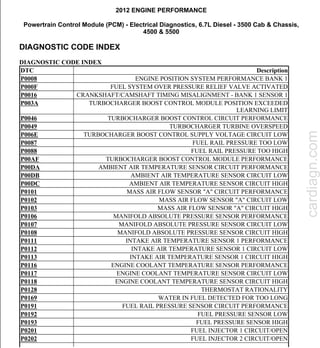
  • 1. 2012 ENGINE PERFORMANCE Powertrain Control Module (PCM) - Electrical Diagnostics, 6.7L Diesel - 3500 Cab & Chassis, 4500 & 5500 DIAGNOSTIC CODE INDEX DIAGNOSTIC CODE INDEX DTC Description P0008 ENGINE POSITION SYSTEM PERFORMANCE BANK 1 P000F FUEL SYSTEM OVER PRESSURE RELIEF VALVE ACTIVATED P0016 CRANKSHAFT/CAMSHAFT TIMING MISALIGNMENT - BANK 1 SENSOR 1 P003A TURBOCHARGER BOOST CONTROL MODULE POSITION EXCEEDED LEARNING LIMIT P0046 TURBOCHARGER BOOST CONTROL CIRCUIT PERFORMANCE P0049 TURBOCHARGER TURBINE OVERSPEED P006E TURBOCHARGER BOOST CONTROL SUPPLY VOLTAGE CIRCUIT LOW P0087 FUEL RAIL PRESSURE TOO LOW P0088 FUEL RAIL PRESSURE TOO HIGH P00AF TURBOCHARGER BOOST CONTROL MODULE PERFORMANCE P00DA AMBIENT AIR TEMPERATURE SENSOR CIRCUIT PERFORMANCE P00DB AMBIENT AIR TEMPERATURE SENSOR CIRCUIT LOW P00DC AMBIENT AIR TEMPERATURE SENSOR CIRCUIT HIGH P0101 MASS AIR FLOW SENSOR "A" CIRCUIT PERFORMANCE P0102 MASS AIR FLOW SENSOR "A" CIRCUIT LOW P0103 MASS AIR FLOW SENSOR "A" CIRCUIT HIGH P0106 MANIFOLD ABSOLUTE PRESSURE SENSOR PERFORMANCE P0107 MANIFOLD ABSOLUTE PRESSURE SENSOR CIRCUIT LOW P0108 MANIFOLD ABSOLUTE PRESSURE SENSOR CIRCUIT HIGH P0111 INTAKE AIR TEMPERATURE SENSOR 1 PERFORMANCE P0112 INTAKE AIR TEMPERATURE SENSOR 1 CIRCUIT LOW P0113 INTAKE AIR TEMPERATURE SENSOR 1 CIRCUIT HIGH P0116 ENGINE COOLANT TEMPERATURE SENSOR PERFORMANCE P0117 ENGINE COOLANT TEMPERATURE SENSOR CIRCUIT LOW P0118 ENGINE COOLANT TEMPERATURE SENSOR CIRCUIT HIGH P0128 THERMOSTAT RATIONALITY P0169 WATER IN FUEL DETECTED FOR TOO LONG P0191 FUEL RAIL PRESSURE SENSOR CIRCUIT PERFORMANCE P0192 FUEL PRESSURE SENSOR LOW P0193 FUEL PRESSURE SENSOR HIGH P0201 FUEL INJECTOR 1 CIRCUIT/OPEN P0202 FUEL INJECTOR 2 CIRCUIT/OPEN cardiagn.com
  • 2. P0203 FUEL INJECTOR 3 CIRCUIT/OPEN P0204 FUEL INJECTOR 4 CIRCUIT/OPEN P0205 FUEL INJECTOR 5 CIRCUIT/OPEN P0206 FUEL INJECTOR 6 CIRCUIT/OPEN P020A FUEL INJECTOR 1 PERFORMANCE P020B FUEL INJECTOR 2 PERFORMANCE P020C FUEL INJECTOR 3 PERFORMANCE P020D FUEL INJECTOR 4 PERFORMANCE P020E FUEL INJECTOR 5 PERFORMANCE P020F FUEL INJECTOR 6 PERFORMANCE P0217 COOLANT TEMPERATURE TOO HIGH P0219 ENGINE OVERSPEED P0253 INJECTION PUMP FUEL CONTROL CIRCUIT LOW P0254 INJECTION PUMP FUEL CONTROL CIRCUIT HIGH P0255 INJECTION PUMP FUEL CONTROL CIRCUIT PERFORMANCE P026A CHARGE AIR COOLER EFFICIENCY BELOW THRESHOLD P0299 MANIFOLD PRESSURE SENSOR OUT OF RANGE LOW P02E1 DIESEL INTAKE AIR FLOW CONTROL PERFORMANCE P02E2 DIESEL INTAKE AIR FLOW CONTROL CIRCUIT LOW P02E3 DIESEL INTAKE AIR FLOW CONTROL CIRCUIT HIGH P02E7 DIESEL INTAKE AIR FLOW POSITION SENSOR PERFORMANCE P02E8 DIESEL INTAKE AIR FLOW POSITION SENSOR CIRCUIT LOW P02E9 DIESEL INTAKE AIR FLOW POSITION SENSOR CIRCUIT HIGH P0300 MULTIPLE CYLINDER MISFIRE P0301 CYLINDER 1 MISFIRE P0302 CYLINDER 2 MISFIRE P0303 CYLINDER 3 MISFIRE P0304 CYLINDER 4 MISFIRE P0305 CYLINDER 5 MISFIRE P0306 CYLINDER 6 MISFIRE P0335 CRANKSHAFT POSITION SENSOR CIRCUIT P0336 CRANKSHAFT POSITION SENSOR PERFORMANCE P0340 CAMSHAFT POSITION SENSOR CIRCUIT - BANK 1 SENSOR 1 P0341 CAMSHAFT POSITION SENSOR PERFORMANCE - BANK 1 SENSOR 1 P0381 WAIT TO START LAMP INOPERATIVE P0401 EGR SYSTEM PERFORMANCE P0402 EGR FLOW EXCESSIVE DETECTED P0404 EGR CONTROL CIRCUIT PERFORMANCE P0405 EGR POSITION SENSOR CIRCUIT LOW P040B EXHAUST GAS RECIRCULATION TEMPERATURE SENSOR "A" CIRCUIT PERFORMANCE cardiagn.com
  • 3. P040C EXHAUST GAS RECIRCULATION TEMPERATURE SENSOR "A" CIRCUIT LOW P040D EXHAUST GAS RECIRCULATION TEMPERATURE SENSOR "A" CIRCUIT HIGH P0420 CATALYST EFFICIENCY BELOW THRESHOLD P0461 FUEL LEVEL SENSOR 1 PERFORMANCE P0462 FUEL LEVEL SENSOR 1 CIRCUIT LOW P0463 FUEL LEVEL SENSOR 1 CIRCUIT HIGH P046C EGR POSITION SENSOR CIRCUIT PERFORMANCE P0471 EXHAUST PRESSURE SENSOR 1 PERFORMANCE P0472 EXHAUST PRESSURE SENSOR 1 LOW P0473 EXHAUST PRESSURE SENSOR 1 HIGH P0489 EGR CONTROL CIRCUIT LOW P049D EGR CONTROL POSITION EXCEEDED LEARNING LIMIT P04DB CRANKCASE VENTILATION SYSTEM DISCONNECTED P0501 VEHICLE SPEED SENSOR 1 PERFORMANCE P0506 IDLE CONTROL SYSTEM RPM - LOWER THAN EXPECTED P0507 IDLE CONTROL SYSTEM RPM - HIGHER THAN EXPECTED P0513 INVALID WIN KEY P051B CRANKCASE PRESSURE SENSOR CIRCUIT RANGE/PERFORMANCE P051C CRANKCASE PRESSURE SENSOR CIRCUIT LOW P051D CRANKCASE PRESSURE SENSOR CIRCUIT HIGH P0521 ENGINE OIL PRESSURE SENSOR PERFORMANCE P0524 ENGINE OIL PRESSURE SENSOR CIRCUIT LOW P0532 A/C PRESSURE SENSOR CIRCUIT LOW P0533 A/C PRESSURE SENSOR CIRCUIT HIGH P0541 INTAKE AIR HEATER CONTROL CIRCUIT 1 LOW P0542 INTAKE AIR HEATER CONTROL CIRCUIT 1 HIGH P0545 EXHAUST GAS TEMPERATURE SENSOR CIRCUIT LOW - BANK 1 SENSOR 1 P0546 EXHAUST GAS TEMPERATURE SENSOR CIRCUIT HIGH - BANK 1 SENSOR 1 P0562 BATTERY VOLTAGE LOW P0563 BATTERY VOLTAGE HIGH P056D REDUCTANT CONTROL MODULE SYSTEM VOLTAGE P0571 BRAKE SWITCH 1 PERFORMANCE P0572 BRAKE SWITCH 1 STUCK ON P0573 BRAKE SWITCH 1 STUCK OFF P0579 SPEED CONTROL SWITCH 1 PERFORMANCE P0580 SPEED CONTROL SWITCH 1 CIRCUIT LOW P0581 SPEED CONTROL SWITCH 1 CIRCUIT HIGH P0585 SPEED CONTROL SWITCH 1/2 CORRELATION cardiagn.com
  • 4. P0591 SPEED CONTROL SWITCH 2 PERFORMANCE P0592 SPEED CONTROL SWITCH 2 CIRCUIT LOW P0593 SPEED CONTROL SWITCH 2 CIRCUIT HIGH P0601 INTERNAL MEMORY CHECKSUM ERROR P0604 INTERNAL CONTROL MODULE RAM ERROR P0606 INTERNAL CONTROL PROCESSOR P0607 ECU INTERNAL PERFORMANCE P061A ETC LEVEL 2 TORQUE PERFORMANCE P061C ETC LEVEL 2 RPM PERFORMANCE P0625 GENERATOR FIELD CONTROL CIRCUIT LOW P0626 GENERATOR FIELD CONTROL CIRCUIT HIGH P0628 FUEL PUMP CONTROL CIRCUIT LOW P0629 FUEL PUMP CONTROL CIRCUIT HIGH P062C ETC LEVEL 2 MPH PERFORMANCE P0630 VIN NOT PROGRAMMED IN PCM P0633 SKIM SECRET KEY NOT STORED IN PCM P063C GENERATOR VOLTAGE SENSE LOW P063D GENERATOR VOLTAGE SENSE HIGH P0642 SENSOR REFERENCE VOLTAGE 1 CIRCUIT LOW P0643 SENSOR REFERENCE VOLTAGE 1 CIRCUIT HIGH P0646 A/C CONTROL CIRCUIT LOW P0647 A/C CONTROL CIRCUIT HIGH P064C GLOW PLUG MODULE INTERNAL PERFORMANCE P0652 SENSOR REFERENCE VOLTAGE 2 LOW P0653 SENSOR REFERENCE VOLTAGE 2 HIGH P0658 ACTUATOR SUPPLY VOLTAGE "A" CIRCUIT LOW P0686 POWER ENABLE CONTROL CIRCUIT LOW P0691 COOLING FAN 1 CONTROL CIRCUIT LOW P0692 COOLING FAN 1 CONTROL CIRCUIT HIGH P0698 SENSOR REFERENCE VOLTAGE 3 CIRCUIT LOW P0699 SENSOR REFERENCE VOLTAGE 3 CIRCUIT HIGH P06A4 SENSOR REFERENCE VOLTAGE 4 CIRCUIT LOW P06A5 SENSOR REFERENCE VOLTAGE 4 CIRCUIT HIGH P06F3 (DIESEL EXHAUST FLUID) REDUCTANT CONTROL MODULE INTERNAL TEMPERATURE SENSOR CIRCUIT HIGH P0700 TRANSMISSION CONTROL SYSTEM (MIL REQUEST) P0850 PARK/NEUTRAL SWITCH PERFORMANCE P1123 POWER TAKE OFF SYSTEM MONITOR CONTROL ERROR P1191 P1191 - INLET AIR TEMPERATURE SENSOR RATIONAL/PERFORMANCE P1192 INLET AIR TEMPERATURE SENSOR CIRCUIT LOW P1193 INLET AIR TEMPERATURE SENSOR CIRCUIT HIGH cardiagn.com
  • 5. P1451 DIESEL PARTICULATE FILTER SYSTEM PERFORMANCE P1484 CATALYST OVERHEAT DETECTION P1507 CRANKCASE FILTER RESTRICTION P1593 SPEED CONTROL SWITCH 1 STUCK P1C54 SCR NOx CATALYST MISSING P1C55 NOx SENSOR INTERMITTENT - BANK 1 SENSOR 1 P1C56 NOx SENSOR INTERMITTENT - BANK 1 SENSOR 2 P1C57 REDUCTANT CONTROL MODULE SHUTDOWN - CRASH EVENT DETECTED P1C6F (DIESEL EXHAUST FLUID) REDUCTANT LINE HEATER RELAY CIRCUIT PERFORMANCE P1C70 SCR ERROR DETECTED - ENGINE DISABLED P2002 DIESEL PARTICULATE FILTER EFFICIENCY BELOW THRESHOLD P202A (DIESEL EXHAUST FLUID) REDUCTANT TANK HEATER CONTROL CIRCUIT OPEN P202B (DIESEL EXHAUST FLUID) REDUCTANT TANK HEATER CONTROL CIRCUIT LOW P202C (DIESEL EXHAUST FLUID) REDUCTANT TANK HEATER CONTROL CIRCUIT HIGH P202E (DIESEL EXHAUST FLUID) REDUCTANT INJECTOR PERFORMANCE P2032 EXHAUST GAS TEMPERATURE SENSOR CIRCUIT LOW- BANK 1 SENSOR 2 P2033 EXHAUST GAS TEMPERATURE SENSOR CIRCUIT HIGH - BANK 1 SENSOR 2 P203C (DIESEL EXHAUST FLUID) REDUCTANT LEVEL SENSOR CIRCUIT LOW P203D (DIESEL EXHAUST FLUID) REDUCTANT LEVEL SENSOR CIRCUIT HIGH P203F (DIESEL EXHAUST FLUID) REDUCTANT LEVEL TOO LOW P2048 (DIESEL EXHAUST FLUID) REDUCTANT INJECTOR CIRCUIT LOW P2049 (DIESEL EXHAUST FLUID) REDUCTANT INJECTOR CIRCUIT HIGH P204A (DIESEL EXHAUST FLUID) REDUCTANT PRESSURE SENSOR CIRCUIT P204B (DIESEL EXHAUST FLUID) REDUCTANT PRESSURE SENSOR CIRCUIT PERFORMANCE P204C (DIESEL EXHAUST FLUID) REDUCTANT PRESSURE SENSOR CIRCUIT LOW P204D (DIESEL EXHAUST FLUID) REDUCTANT PRESSURE SENSOR CIRCUIT HIGH P204E (DIESEL EXHAUST FLUID) REDUCTANT PRESSURE SENSOR CIRCUIT INTERMITTENT P205B (DIESEL EXHAUST FLUID) REDUCTANT TANK TEMPERATURE SENSOR CIRCUIT RANGE/PERFORMANCE P205C (DIESEL EXHAUST FLUID) REDUCTANT TANK TEMPERATURE SENSOR CIRCUIT LOW P205D (DIESEL EXHAUST FLUID) REDUCTANT TANK TEMPERATURE SENSOR cardiagn.com
  • 6. CIRCUIT HIGH P205E (DIESEL EXHAUST FLUID) REDUCTANT TANK TEMPERATURE SENSOR CIRCUIT INTERMITTENT P207F REDUCTANT QUALITY PERFORMANCE P2080 EXHAUST GAS TEMP SENSOR CIRCUIT PERFORMANCE - BANK 1 SENSOR 1 P2084 EXHAUST GAS TEMP SENSOR CIRCUIT PERFORMANCE - BANK 1 SENSOR 2 P208A (DIESEL EXHAUST FLUID) REDUCTANT PUMP CONTROL CIRCUIT OPEN P208B (DIESEL EXHAUST FLUID) REDUCTANT PUMP PERFORMANCE P208C (DIESEL EXHAUST FLUID) REDUCTANT PUMP CONTROL CIRCUIT LOW P208D (DIESEL EXHAUST FLUID) REDUCTANT PUMP CONTROL CIRCUIT HIGH P209F (DIESEL EXHAUST FLUID) REDUCTANT TANK HEATER CONTROL CIRCUIT PERFORMANCE P20A0 (DIESEL EXHAUST FLUID) REDUCTANT PURGE CONTROL VALVE CIRCUIT OPEN P20A2 (DIESEL EXHAUST FLUID) REDUCTANT PURGE CONTROL VALVE CIRCUIT LOW P20A3 (DIESEL EXHAUST FLUID) REDUCTANT PURGE CONTROL VALVE CIRCUIT HIGH P20B0 (DIESEL EXHAUST FLUID) REDUCTANT PUMP TEMPERATURE PERFORMANCE P20B2 (DIESEL EXHAUST FLUID) REDUCTANT HEATER CONTROL VALVE PERFORMANCE P20B5 (DIESEL EXHAUST FLUID) REDUCTANT PUMP HEATER CONTROL CIRCUIT OPEN P20B7 (DIESEL EXHAUST FLUID) REDUCTANT PUMP HEATER CONTROL CIRCUIT LOW P20B8 (DIESEL EXHAUST FLUID) REDUCTANT PUMP HEATER CONTROL CIRCUIT HIGH P20BD (DIESEL EXHAUST FLUID) REDUCTANT PRESSURE LINE HEATER CONTROL CIRCUIT/OPEN P20BE (DIESEL EXHAUST FLUID) REDUCTANT PRESSURE LINE HEATER CONTROL CIRCUIT PERFORMANCE P20BF (DIESEL EXHAUST FLUID) REDUCTANT PRESSURE LINE HEATER CONTROL CIRCUIT LOW P20C0 (DIESEL EXHAUST FLUID) REDUCTANT PRESSURE LINE HEATER CONTROL CIRCUIT HIGH P20C1 (DIESEL EXHAUST FLUID) REDUCTANT RETURN LINE HEATER CONTROL CIRCUIT/OPEN P20C3 (DIESEL EXHAUST FLUID) REDUCTANT RETURN LINE HEATER CONTROL CIRCUIT LOW P20C4 (DIESEL EXHAUST FLUID) REDUCTANT RETURN LINE HEATER CONTROL CIRCUIT HIGH cardiagn.com
  • 7. P20C6 (DIESEL EXHAUST FLUID) REDUCTANT HEATER D CONTROL PERFORMANCE P20E8 (DIESEL EXHAUST FLUID) REDUCTANT PRESSURE TOO LOW P20E9 (DIESEL EXHAUST FLUID) REDUCTANT PRESSURE TOO HIGH P20EC SCR NOx CATALYST - OVER TEMPERATURE BANK 1 P20EE SCR NOx CATALYST EFFICIENCY BELOW THRESHOLD - BANK 1 P20FE (DIESEL EXHAUST FLUID) REDUCTANT METERING UNIT PERFORMANCE P20FF (DIESEL EXHAUST FLUID) REDUCTANT CONTROL MODULE PERFORMANCE P2121 ACCELERATOR PEDAL POSITION SENSOR 1 PERFORMANCE P2122 ACCELERATOR PEDAL POSITION SENSOR 1 CIRCUIT LOW P2123 ACCELERATOR PEDAL POSITION SENSOR 1 CIRCUIT HIGH P2127 ACCELERATOR PEDAL POSITION SENSOR 2 CIRCUIT LOW P2128 ACCELERATOR PEDAL POSITION SENSOR 2 CIRCUIT HIGH P214A SCR NOx CATALYST INLET TEMPERATURE TOO HIGH P214B SCR NOx CATALYST INLET TEMPERATURE TOO HIGH DURING PARTICULATE FILTER REGENERATION P214C SCR NOx CATALYST OUTLET TEMPERATURE TOO HIGH P214D SCR NOx CATALYST OUTLET TEMPERATURE TOO HIGH DURING PARTICULATE FILTER REGENERATION P21C2 (DIESEL EXHAUST FLUID) REDUCTANT LINE HEATER RELAY CONTROL CIRCUIT OPEN P21C3 (DIESEL EXHAUST FLUID) REDUCTANT LINE HEATER RELAY CONTROL CIRCUIT LOW P21C4 (DIESEL EXHAUST FLUID) REDUCTANT LINE HEATER RELAY CONTROL CIRCUIT HIGH P2201 AFTERTREATMENT NOx SENSOR CIRCUIT PERFORMANCE - BANK 1 SENSOR 1 P2202 AFTERTREATMENT NOx SENSOR CIRCUIT - BANK 1 SENSOR 1 P2209 NOx SENSOR HEATER CIRCUIT PERFORMANCE - BANK 1 SENSOR 1 P220A NOx SENSOR SUPPLY CIRCUIT PERFORMANCE - BANK 1 SENSOR 1 P220B NOx SENSOR SUPPLY CIRCUIT PERFORMANCE - BANK 1 SENSOR 2 P2227 BAROMETERIC PRESSURE SENSOR RATIONALITY P2228 BAROMETRIC PRESSURE CIRCUIT LOW P2229 BAROMETRIC PRESSURE CIRCUIT HIGH P2262 TURBOCHARGER BOOST PRESSURE NOT DETECTED - MECHANICAL P2266 WATER IN FUEL SENSOR CIRCUIT LOW P2267 WATER IN FUEL SENSOR CIRCUIT HIGH P2269 WATER IN FUEL CONDITION P226B TURBOCHARGER BOOST PRESSURE NOT RESPONDING P226C TURBOCHARGER BOOST CONTROL "A" SLOW RESPONSE cardiagn.com
  • 8. P2280 AIR FLOW RESTRICTION / LEAK BETWEEN AIR CLEANER AND MAF P2281 AIR LEAK BETWEEN MAF AND THROTTLE BODY P2299 BRAKE PEDAL POSITION / ACCELERATOR PEDAL POSITION INCOMPATIBLE P229E AFTERTREATMENT NOx SENSOR CIRCUIT - BANK 1 SENSOR 2 P229F AFTERTREATMENT NOx SENSOR CIRCUIT PERFORMANCE - BANK 1 SENSOR 2 P22A7 NOx SENSOR HEATER CIRCUIT PERFORMANCE - BANK 1 SENSOR 2 P240F EGR SLOW RESPONSE P242B EXHAUST GAS TEMP SENSOR CIRCUIT PERFORMANCE - BANK 1 SENSOR 3 P242C EXHAUST GAS TEMPERATURE SENSOR CIRCUIT LOW- BANK 1 SENSOR 3 P242D EXHAUST GAS TEMPERATURE SENSOR CIRCUIT HIGH - BANK 1 SENSOR 3 P242F DIESEL PARTICULATE FILTER RESTRICTION - ASH ACCUMULATION P244A DIESEL PARTICULATE FILTER DIFFERENTIAL PRESSURE TOO LOW P244D EXHAUST TEMPERATURE TOO HIGH FOR PARTICULATE FILTER REGENERATION P2453 DIESEL PARTICULATE FILTER PRESSURE SENSOR A CIRCUIT PERFORMANCE P2454 DIESEL PARTICULATE FILTER PRESSURE SENSOR A CIRCUIT LOW P2455 DIESEL PARTICULATE FILTER PRESSURE SENSOR A CIRCUIT HIGH P2457 EXHAUST GAS RECIRCULATION COOLING SYSTEM PERFORMANCE P2459 DIESEL PARTICULATE FILTER REGENERATION TOO FREQUENT P2463 DIESEL PARTICULATE FILTER - SOOT ACCUMULATION P246F EXHAUST GAS TEMP SENSOR CIRCUIT PERFORMANCE - BANK 1 SENSOR 4 P2470 EXHAUST GAS TEMPERATURE SENSOR CIRCUIT LOW - BANK 1 SENSOR 4 P242D EXHAUST GAS TEMPERATURE SENSOR CIRCUIT HIGH - BANK 1 SENSOR 4 P249C EXCESSIVE TIME TO ENTER CLOSED LOOP SCR REDUCTANT INJECTION CONTROL P249E CLOSED LOOP SCR REDUCTANT INJECTION CONTROL AT LIMIT - FLOW TOO HIGH P249F EXCESSIVE TIME TO ENTER CLOSED LOOP DPF REGENERATION CONTROL P24A0 CLOSED LOOP DPF REGENERATION CONTROL AT LIMIT - TEMPERATURE TOO LOW P2503 CHARGING SYSTEM OUTPUT LOW P2504 CHARGING SYSTEM OUTPUT HIGH P2509 PCM/PCM POWER INPUT SIGNAL INTERMITTENT cardiagn.com
  • 9. P2563 TURBOCHARGER BOOST CONTROL POSITION SENSOR PERFORMANCE P2579 TURBOCHARGER SPEED SENSOR CIRCUIT PERFORMANCE P2580 TURBOCHARGER SPEED SENSOR CIRCUIT LOW P2609 INTAKE AIR HEATER SYSTEM PERFORMANCE P268C CYLINDER 1 INJECTOR DATA INCOMPATIBLE P268D CYLINDER 2 INJECTOR DATA INCOMPATIBLE P268E CYLINDER 3 INJECTOR DATA INCOMPATIBLE P268F CYLINDER 4 INJECTOR DATA INCOMPATIBLE P2690 CYLINDER 5 INJECTOR DATA INCOMPATIBLE P2691 CYLINDER 6 INJECTOR DATA INCOMPATIBLE P2BAC NOx EXCEEDANCE - DEACTIVATION OF EGR U0001 CAN C BUS U0101 LOST COMMUNICATION WITH TCM U010C LOST COMMUNICATION WITH TURBOCHARGER/SUPERCHARGER CONTROL MODULE U010E LOST COMMUNICATION WITH DIESEL EXHAUST FLUID CONTROL UNIT U0121 LOST COMMUNICATION WITH ANTI-LOCK BRAKE MODULE U0141 LOST COMMUNICATION WITH IPM (FCM/TIPM) U029D LOST COMMUNICATION WITH NOx SENSOR "A" U029E LOST COMMUNICATION WITH NOx SENSOR "B" U040F INVALID DATA RECEIVED FROM REDUCTANT CONTROL MODULE U059E INVALID DATA RECEIVED FROM NOx SENSOR "A" U059F INVALID DATA RECEIVED FROM NOx SENSOR "B" U11C1 LOST COMMUNICATION WITH DIESEL EXHAUST FLUID CONTROL UNIT U1403 IMPLAUSIBLE FUEL LEVEL SIGNAL RECEIVED U1412 IMPLAUSIBLE VEHICLE SPEED SIGNAL RECEIVED U1421 IMPLAUSIBLE IGNITION KEY OFF TIME RECEIVED U1601 ECU APPLICATION SOFTWARE CODE 1 MISSING OR CORRUPTED cardiagn.com
  • 10. 2012 ENGINE PERFORMANCE Powertrain Control Module (PCM) - Electrical Diagnostics, 6.7L Diesel - 3500 Cab & Chassis, 4500 & 5500 STANDARD PROCEDURE DIESEL AFTERTREATMENT VALIDATION- 6.7L Fig. 1: Diesel Aftertreatment System Diagram Courtesy of CHRYSLER GROUP, LLC SOOT GENERATION CAUSES AND EFFECTS When trying to understand the functionality of the exhaust and aftertreatment system, (more precisely the effects on the Diesel Particulate Filter (DPF)) you must think in terms of standard plumbing principals. Everything flows downstream. Systems and components along the path are affected by the soot in the exhaust, and these components can also contribute to the soot levels (cause and effect). This overview will attempt to elaborate on the causes and effects of the Soot flowing downstream in the system. The soot originates in the combustion chamber as a by-product of the combustion process. This is the beginning of the stream. All soot generated in the combustion chamber flows downstream. Excessive amounts of soot can be caused by faulty inputs to the engine controller, air handling system leaks or restrictions, fuel contamination, or fuel injectors. Some soot will always be generated. Under proper operating conditions, soot levels will be low cardiagn.com
  • 11. and very manageable. The next component downstream is the EGR. The EGR can be affected by soot coming from the combustion process. The soot can cause the EGR to stick open or closed, or become restricted. If the EGR malfunctions, it can cause soot generation which is then added to system. The next component downstream is the Turbocharger. The Turbocharger can be affected by soot coming from the combustion process and/or the EGR. If the Turbocharger malfunctions (sticks, or leaks oil or coolant internally), it can cause soot generation which is then added to system. The next components found downstream are the O2 Sensors. The O2 Sensors can be affected by soot coming from the combustion process, the EGR, and/or the Turbocharger. If an O2 Sensor malfunctions, it can cause (to a much lesser extent) soot generation which is added to system. O2 Sensor codes can be caused by excessive soot. ALL of the soot generated upstream will land in the DPF. If a vehicle sets a DPF DTC, such as P1451 or P242F, which are related to the calculated amount of soot currently caught in the DPF this means the engine controller has calculated that the DPF is getting full. This number is and estimation, hence the name; "Estimated Soot Load Based on Delta" (ESL/D) and is measured in grams. Sometimes soot levels will be estimated high and set faults and there is little soot in the DPF! When a DPF fault sets, it is important to root cause the reason the soot landed in the filter and could not be removed through a normal regeneration. Is fuel contamination the issue causing injectors to stick and over fuel? Is the EGR or Turbocharger sticking causing excess soot? Or is it a combination of these? A DPF should NEVER be replaced without first determining if there is another root cause of the source of the high "Estimated Soot Load Based on Delta" and repairing this issue also. A DPF should also not be replaced without performing the AFTERTREATMENT INSPECTION GUIDELINE procedure. This will visually show you with examples how to determine if replacement of an aftertreatment component is necessary. DIAGNOSTIC TEST 1. VALIDATION 1. Before starting the validation, confirm on the scan tool that the engine is still at an operating temperature of 180°F (82°C). 2. The technician must perform a short light load steady state drive cycle to ensure the vehicle will operate normally and allow a passive regeneration if necessary during the next step. During the NOTE: The following procedure will provide the necessary drive cycle to allow the PCM to learn normal system operation and the ability to detect most aftertreatment sooting issues. It is not necessary to have a technician perform the 50 minute drive cycle however, the technician must verify Estimated Soot Load Based on Delta" (ESL/D), measured in Grams while driving the vehicle at a steady state speed. The technician will monitor the scan tool while another person drives the vehicle. cardiagn.com
  • 12. drive cycle monitor Estimated Soot Load Based on Delta" (ESL/D), measured in Grams for a short period to ensure that the Diesel Particulate Filter (DPF) will not plug during the next steps. In addition, illumination of the MIL during the drive cycle indicates that further diagnosis may be required before proceeding. 3. Record the mileage from the vehicle odometer into section 4D "After Treatment Validation Test" of the Diesel Diagnostic Worksheet step 1. 4. Have an associate (porter) drive at the vehicle least 50 minutes at a steady state speed so the RPM is maintained at about 1900. If highway access is not available, use a lower gear on surface streets. A steady throttle is important. Use cruise control if possible. 5. Once the initial 50 minute drive cycle is complete, return to the repair shop and record the mileage from the vehicle odometer into section 4D "After Treatment Validation Test" of the Diesel Diagnostic Worksheet step 2. Turn the ignition key to OFF. 6. Have the associate restart the engine and record the key cycle event into step 3 of section 4D "After Treatment Validation Test" of the Diesel Diagnostic Worksheet. 7. The technician will ride in the passenger seat while monitoring the scan tool. Monitor "Estimated Soot Load Based on Delta" (ESL/D), measured in Grams. 8. Drive the vehicle and maintain steady engine speed of 1800 - 1900 RPM. Use cruise control if possible, (steady throttle pressure). 9. ESL/D should maintain steady or even start to decrease slowly even though truck is NOT in deSoot mode. This is because the latest software may actually "scrub" soot when driving at higher speeds. 10. Ensure vehicle is operating in "Normal" mode. (Not in desoot, desox or denox mode). 11. Take a reading of the ESL/D. Record the ESLD into step 4 of section 4D "After Treatment Validation Test" of the Diesel Diagnostic Worksheet and continue to drive for 10 minutes. 12. Record that the 10 minute drive cycle has been completed in step 5 of section 4D "After Treatment Validation Test" of the Diesel Diagnostic Worksheet. 13. After 10 minutes, take another reading of the ESL/D and record this number in step 6 of section 4D "After Treatment Validation Test" of the Diesel Diagnostic Worksheet. 14. Step 7 of section 4D "After Treatment Validation Test" of the Diesel Diagnostic Worksheet will automatically calculate the estimated soot load difference. 15. Step 8 of section 4D "After Treatment Validation Test" of the Diesel Diagnostic Worksheet will automatically PASS or FAIL based upon results of step 7 of section 4D "After Treatment Validation Test" of the Diesel Diagnostic Worksheet. Did the ESL/D test pass? Yes  Vehicle is properly repaired. NOTE: If the soot load threshold for a P242F DTC is reached during this short drive cycle, the mil will illuminate and passive regeneration will not occur. cardiagn.com
  • 13. No  Vehicle is NOT repaired completely. Return back to the test that sent you here or continue diagnosing the vehicle with the ENGINE MISFIRE/RUNS ROUGH/POOR PERFORMANCE test procedure. Refer to DIAGNOSIS AND TESTING, 6.7L . MIL LIGHT ON PRETEST PROCEDURE For a complete wiring diagram, Refer to appropriate SYSTEM WIRING DIAGRAMS article . DIAGNOSTIC TEST 1. FUEL SYSTEM, AIR HANDLING, OR AFTERTREATMENT RELATED DTCS PRESENT 1. With the scan tool, read and record all DTCs active and stored. Are any one or more of the following DTCs present (P000F, P0087, P0402, P042E, P0489, P1011, P1451, P2262, P226B, P242F, P245A, P2563)? Yes  Go To 2. No  Go To 5. 2. VISUALLY INSPECT FOR SIGNS OF AFTERMARKET COMPONENTS 1. Inspect for aftermarket engine components on the vehicle (including labels indicating aftermarket software). Is the vehicle equipped with aftermarket performance software/parts? Yes  Performance enhancing software/parts may be the root cause of the customers concern. Performance enhancing software should be removed and the vehicle returned to stock before proceeding.  Go To 3. CAUTION: Inspect for aftermarket engine components on the vehicle (including labels indicating aftermarket software). If equipped with aftermarket components or software, the vehicle must be returned to OEM specifications. NOTE: If equipped with aftermarket components or software, the vehicle must be returned to OEM specifications. cardiagn.com
  • 14. No  Go To 3. 3. REVIEW VEHICLE WARRANTY HISTORY 1. Review vehicle warranty history and/or previously authorized Diesel Diagnostic Worksheets to determine if the vehicle has returned for a repeat repair. Has the vehicle returned within the last 90 days for a repeat with any of the following DTCs present, P000F, P0087, P0402, P042E, P0489, P1011, P1451, P2262, P226B, P242F, P245A, P2563? Yes  Perform the DIESEL FUEL CONTAMINATION AND CLEANING PROCEDURE. Refer to DIESEL FUEL SYSTEM CLEANING PROCEDURE . No  Go To 4. 4. VISUALLY INSPECT FOR EXTERNAL SIGNS OF FUEL CONTAMINATION 1. Inspect the vehicle for the following conditions:  Review the vehicles repair history and verify proper Fuel Filter maintenance intervals have been followed.  Auxiliary fuel tank that is CONNECTED to the vehicles fuel system or used as a STORAGE tank to fill the truck.  Fuel stains on outside and inside of truck box/bed. This may be in indication that the driver is fueling the vehicle from an auxiliary source.  Inspect the fuel filler cap, filler tube, and fuel filler cavity for signs of dirt and possible overfilling. Most auxiliary fuel tanks do not contain automatic shut off filler valves which may lead to over filling of the fuel tank.  Inspect the top of the vehicles fuel tank for excessive oily dirt stains. Sometimes, gravity feed auxiliary fuel tank installers may feed the vehicles fuel tank from the auxiliary tank through the fuel tank vent valves.  Inspect the fuel tank vent valves for signs of dirt or moisture contamination.  Both P1451 AND P242F are the ONLY DTCs present. Were any of the above conditions noted? Yes  Perform the DIESEL FUEL CONTAMINATION AND CLEANING PROCEDURE. Refer to DIESEL FUEL SYSTEM CLEANING PROCEDURE . No cardiagn.com
  • 15.  Go To 5. 5. CHECK FOR TSBs/SOFTWARE FLASHES 1. Check for any TSBs/Software Flashes that may apply. Were any TSBs/Software Flashes found and did they repair the problem? Yes  Repair complete.  Perform POWERTRAIN VERIFICATION TEST - 6.7L. Refer to POWERTRAIN VERIFICATION TEST - 6.7L . No  Perform the diagnostic trouble code test that was found to be present. Refer to DIAGNOSTIC CODE INDEX . PRE-DIAGNOSTIC TROUBLESHOOTING PROCEDURE - 6.7L For a complete wiring diagram, Refer to appropriate SYSTEM WIRING DIAGRAMS article . DIAGNOSTIC TEST 1. NO RESPONSE 1. Make sure the scan tool will communicate with the appropriate modules. Are you currently experiencing a NO RESPONSE condition? Yes  The NO RESPONSE condition must be properly diagnosed before continuing.  Perform the appropriate BUS Communication test . Refer to DIAGNOSIS AND TESTING . No  Go To 2. 2. DTC PRESENT 1. Turn the ignition on. 2. With the scan tool, view PCM for DTCs. NOTE: Before continuing, complete the 6.7L Cummins Turbo Diesel Diagnostic Worksheet. Go to the TechConnect > submit the vehicle's VIN number > Search Tab > and Select Create Diagnostic Worksheet. cardiagn.com
  • 16. Is there a DTC present? Yes  Proceed to the MIL LIGHT ON PRETEST PROCEDURE. Refer to MIL LIGHT ON PRETEST PROCEDURE . No  Go To 3. 3. CHECK FOR SYMPTOM BASED ISSUES 1. Check the vehicle for one of the following conditions:  Engine No Start / Hard Start  Engine Misfires / Runs Rough / Poor Performance  Engine Noise  Excessive Smoke (Black/Blue/White) Do one of the following conditions exist? Yes  Perform the appropriate symptom based diagnostic procedure. Refer to DIAGNOSIS AND TESTING, 6.7L . No  Verify the vehicles performance by performing the Diesel Fuel System Validation procedure. Refer to DIESEL AFTERTREATMENT VALIDATION- 6.7L . PCM/ECM / TCM PROGRAMMING PCM/ECM / TCM FLASH PROGRAMING This procedure will need to be done when one or more of the following situations are true: 1. A vehicle's Powertrain Control Module/Engine Control Module (PCM/ECM) has been replaced. 2. A diagnostic trouble code (DTC) is set P1602 - PCM/ECM Not Programmed. 3. An updated calibration or software release is available for either the PCM/ECM or TCM ECUs. This procedure assumes that the wiTECH™ Vehicle Connection Interface (VCI) pod, StarSCAN® and StarMOBILE® devices are configured to your dealership's network with either a wired or wireless connection. The wiTECH™ VCI pod, StarSCAN® and StarMOBILE® must also be running at the latest operating system and software release level. For more help on how to network your StarSCAN® or StarMOBILE® reference the StarSCAN® / StarMOBILE® Quick Start Networking Guide available on 'DealerCONNECT > Service > StarSCAN® and StarMOBILE® Tools > Online Documentation' or at www.dcctools.com, under the Download cardiagn.com
  • 17. Center. For the wiTECH™ VCI pod use the "HELP" tab in the wiTECH™ Diagnostic Application. TABLE OF CONTENTS 1. Refer to SECTION 1 - PCM/ECM / TCM FLASH PROCEDURE. 2. Refer to REQUIRED TOOLS / EQUIPMENT: 3. Refer to TECH TIPS AND INFORMATION: 4. Refer to PARTS REQUIRED. SECTION 1 - PCM/ECM / TCM FLASH PROCEDURE If using StarSCAN® or StarMOBILE® Desktop Client. Go to REPAIR PROCEDURE - USING STARSCAN® OR STARMOBILE® DESKTOP CLIENT. If using wiTECH™ Diagnostic Application. Go to REPAIR PROCEDURE - WITECH™ DIAGNOSTIC APPLICATION. REPAIR PROCEDURE - USING STARSCAN® OR STARMOBILE® DESKTOP CLIENT 1. Open the hood of the vehicle and install a battery charger. Verify that the charging rate provides a continuous charge of 13.2 - 13.5 Volts. 2. Connect the StarSCAN® or StarMOBILE® to the vehicle data link connector located under the steering column and turn the ignition key to the "RUN" position. 3. Power on the StarSCAN® or StarMOBILE®. If the StarMOBILE® is being used, launch the StarMOBILE® Desktop Client and connect to the appropriate StarMOBILE® device. 4. Retrieve the old ECU part number. From the tool's Home screen, a. Select "ECU View" b. Select "PCM/ECM" c. Select "More Options" d. Select "ECU Flash" e. Record the part number at the top of the Flash PCM/ECM screen for later reference. 5. Program the ECU as follows: a. Using the StarSCAN® / StarMOBILE® at the Home screen, select "ECU View" b. Select "PCM/ECM" c. Select "More Options" d. Select "ECU Flash" e. Select "Browse for New File" and follow the on screen instructions f. Highlight the appropriate calibration based on the part number recorded in Step 4e , or by using Year/Model/Engine and appropriate emissions selection for the vehicle being worked on g. Select "Download to Client/Scantool" NOTE: If this flash process is interrupted or aborted, the flash should be restarted. cardiagn.com
  • 18. h. Once the download is complete, select "Close" and then "Back" i. Highlight the listed calibration, select "Update Controller" and follow the on screen instructions j. When the PCM/ECM update is complete, select "OK" k. Verify that the part number at the top of the Flash PCM/ECM screen has updated to the new part number 6. Continue to complete the process if the ECU has been replaced. 7. Type the necessary information on the "Authorized Modification Label" (p/n 04275086AB) and attach near the VECI label (See Section 3 for details). Refer to SECTION 3 - AUTHORIZED MODIFICATION LABEL. REPAIR PROCEDURE - WITECH™ DIAGNOSTIC APPLICATION 1. Open the hood of the vehicle and install a battery charger. Verify that the charging rate provides a continuous charge of 13.2 - 13.5 Volts. 2. Connect the wiTECH™ Vehicle Connection Interface (VCI) pod to the vehicle data link connector located under the steering column and turn the ignition key to the "RUN" position. 3. Launch the wiTECH™ Diagnostic Application and connect to the appropriate wiTECH™ device. 4. From the wiTECH™ Diagnostic Application Home screen, 1. Select "HELP" 2. Select "HELP CONTENTS" 3. Follow the "HELP TOPIC" for flashing an ECU. SECTION 2 - ADDITIONAL PCM/ECM / TCM REPLACEMENT PROCEDURES If a 2.0L Controller was replaced, navigate to "Misc. Functions" and perform all applicable routines: 1. PCM/ECM Replaced - Located within the Security Module 2. ECU Replacement With Value Transfer - if the ECU to be replaced is still responsive NOTE: If this flash process is interrupted or aborted, the flash should be restarted. NOTE: If this flash process is interrupted or aborted, the flash should be restarted. NOTE: Find the PCM/ECM /TCM Type for the vehicle, read and write down the steps, and then go to the step by step instructions for additional information on how to perform these procedures. Refer to STEP-BY-STEP INSTRUCTIONS. NOTE: The available routines may vary depending on model and year of vehicle. NOTE: If the PCM/ECM data transfer is able to be completed, it may not be necessary to perform routines 7 - 9. cardiagn.com
  • 19. 3. ECU Replacement Without Value Transfer - if the ECU to be replaced is NOT responsive 4. Verify PCM/ECM VIN 5. Injector Quantity Adjustment 6. Program Variant Code 7. Service Diesel Particulate Filter Regeneration 8. Reset Zero Fuel 9. Reset of Lambda Values If a PT Cruiser, 2.2L Controller was replaced, navigate to "Misc. Functions" and perform all applicable routines: 1. PCM/ECM Replaced - Located within the Security Module 2. Injector Quantity Adjustment - Only on 06 PT AND up 3. IMA Rapid Calibration Test - Only on 06 PT AND up If a 3.0L Controller was replaced, navigate to "Misc. Functions" and perform all applicable routines: 1. PCM/ECM Replaced - Located within the Security Module 2. ECU Replacement With Value Transfer - if the ECU to be replaced is still responsive 3. ECU Replacement Without Value Transfer - if the ECU to be replaced is NOT responsive 4. Injector Quantity Adjustment 5. Program Variant Code 6. Verify PCM/ECM VIN 7. Diesel Particulate Filter (Used) Learning 8. Reset of Lambda Values 9. Reset Zero Fuel 10. NOx Catalyst (New) Initialization 11. IMA Rapid Calibration Test 12. Fuel Mean Value Adaptation Initialization 13. Exhaust Throttle Plate Adaptive Learn Position If a 2.8L Controller was replaced, navigate to "Misc. Functions" and perform all applicable routines: NOTE: The available routines may vary depending on model and year of vehicle. NOTE: The available routines may vary depending on model and year of vehicle. NOTE: If the PCM/ECM data transfer is able to be completed, it may not be necessary to perform routines 7 - 12. NOTE: The available routines may vary depending on model and year of vehicle. cardiagn.com
  • 20. 1. PCM/ECM Replaced - Located within the Security Module 2. ECU Replacement With Value Transfer - if the ECU to be replaced is still responsive 3. ECU Replacement Without Value Transfer - if the ECU to be replaced is NOT responsive 4. Injector Quantity Adjustment 5. Program Variant Code 6. Fuel Mean Value Adaptation Initialization 7. IMA Rapid Calibration Test 8. Set Oil Dilution Mass Value If a PM/MK, 2.2L Controller was replaced, navigate to "Misc. Functions" and perform all applicable routines: 1. PCM/ECM Replaced - Located within the Security Module 2. Engine ECU Replacement 3. Injector Quantity Adjustment 4. Program Variant Code 5. Swirl Control Learn 6. Throttle Valve Learn 7. VGT Learn 8. MAF Sensor Replace 9. O2 Sensor Replace 10. Used DPF initialize If a 5.9L Controller was replaced, navigate to "Misc. Functions" and perform all applicable routines: 1. PCM/ECM Replaced - Located within the Security Module 2. Check PCM/ECM VIN - if NOT WCM equipped If a 6.7L Controller was replaced, navigate to "Misc. Functions" and perform all applicable routines: NOTE: If the PCM/ECM data transfer is able to be completed, it may not be necessary to perform routines 6 - 8. NOTE: The available routines may vary depending on model and year of vehicle. NOTE: If the PCM/ECM data transfer is able to be completed, it may not be necessary to perform routines 5 - 10. NOTE: The available routines may vary depending on model and year of vehicle. NOTE: The available routines may vary depending on model and year of vehicle. cardiagn.com
  • 21. 1. PCM/ECM Replaced - Located within the Security Module 2. Injector Quantity Adjustment 3. Enable / Disable Vehicle Features - need to enable features 4. Set max vehicle speed 5. Set max cruise speed 6. Idle shutdown timer 7. PTO RPM adjustment 8. Set PTO Max vehicle speed 9. Reset Regenerative Filter Timers TCM Replacement: If an Aisin TCM was replaced, perform the following additional steps and/or routines: If an EATX TCM was replaced, perform the following additional steps and/or routines: If an NGC3 TCM ONLY was replaced, perform the following additional steps and/or routines: If an NGC4 TCM ONLY was replaced, perform the following additional steps and/or routines: 1. Quicklearn If an EGS TCM was replaced, perform the following additional steps and/or routines: 1. Initialize EGS STEP-BY-STEP INSTRUCTIONS PCM/ECM Replaced The vehicle PIN (Personal Identification Number) will be required to complete the routine. This information may be obtained in three ways: 1. The original selling invoice 2. DealerCONNECT > Parts > Key Codes 3. Contacting the District Manager. From the "Home" screen, select "ECU View" NOTE: The numbers can be retrieved from the old PCM/ECM using the scan tool if the PCM/ECM is still functional or they may be retrieved from the Fuel Injectors themselves. The numbers are stamped on the intake manifold side of the injectors. cardiagn.com
  • 22.  Select the applicable Security Module  Select "Misc. Functions"  Select "PCM/ECM Replaced" and follow the on screen instructions.  When complete, select "Finish" Check PCM VIN From the "Home" screen, select "ECU View"  Select "PCM/ECM"  Select "Misc. Functions"  Select "Check PCM/ECM VIN" and follow the on screen instructions.  When complete, select "Finish" Diesel Particulate Filter (Used) Learning From the "Home" screen, select "ECU View"  Select "PCM/ECM"  Select "Misc. Functions"  Select "Diesel Particulate Filter (Used) Learning" and follow the on screen instructions.  When complete, select "Finish" ECU Replacement with Value Transfer From the "Home" screen, select "ECU View"  Select "PCM/ECM"  Select "Misc. Functions"  Select "ECU Replacement with Value Transfer" and follow the on screen instructions.  When complete, select "Finish" ECU Replacement without Value Transfer From the "Home" screen, select "ECU View"  Select "PCM/ECM"  Select "Misc. Functions"  Select "ECU Replacement without Value Transfer" and follow the on screen instructions.  When complete, select "Finish" Enable / Disable Vehicle Features cardiagn.com
  • 23. From the "Home" screen, select "ECU View"  Select "PCM/ECM"  Select "Misc. Functions"  Select "Enable / Disable Vehicle Features" and follow the on screen instructions.  When complete, select "Finish" Exhaust Throttle Plate Adaptive Learn Position From the "Home" screen, select "ECU View"  Select "PCM/ECM"  Select "Misc. Functions"  Select "Exhaust Throttle Plate Adaptive Learn Position" and follow the on screen instructions.  When complete, select "Finish" Fuel Mean Value Adaptation Initialization From the "Home" screen, select "ECU View"  Select "PCM/ECM"  Select "Misc. Functions"  Select "Fuel Mean Value Adaptation Initialization" and follow the on screen instructions.  When complete, select "Finish" IMA Rapid Calibration From the "Home" screen, select "ECU View"  Select "PCM/ECM"  Select "Misc. Functions"  Select "IMA Rapid Calibration Test" and follow the on screen instructions.  When complete, select "Finish" Initialize EGS From the "Home" screen, select "ECU View"  Select "PCM/ECM"  Select "Misc. Functions"  Select "Initialize EGS" and follow the on screen instructions.  When complete, select "Finish" cardiagn.com
  • 24. Injector Quantity Adjustment From the "Home" screen, select "ECU View"  Select "PCM/ECM"  Select "Misc. Functions"  Select "Injector Quantity Adjustment" and follow the on screen instructions.  When complete, select "Finish" Mobile DeSoot - NO Minimum Required Soot Load From the "Home" screen, select "ECU View"  Select "PCM/ECM"  Select "Misc. Functions"  Select "Mobile DeSoot - NO Minimum Required Soot Load" and follow the on screen instructions.  When complete, select "Finish" NOx Catalyst (New) Initialization From the "Home" screen, select "ECU View"  Select "PCM/ECM"  Select "Misc. Functions"  Select "NOx Catalyst (New) Initialization" and follow the on screen instructions.  When complete, select "Finish" Program Variant Code From the "Home" screen, select "ECU View"  Select "PCM/ECM"  Select "Misc. Functions"  Select "Program Variant Code" and follow the on screen instructions.  When complete, select "Finish" Quicklearn From the "Home" screen, select "ECU View"  Select "PCM/ECM"  Select "Misc. Functions"  Select "Quicklearn" and follow the on screen instructions. cardiagn.com
  • 25.  When complete, select "Finish" Reset Regenerative Filter Timers From the "Home" screen, select "ECU View"  Select "PCM/ECM"  Select "Misc. Functions"  Select "Reset Regenerative Filter Times" and follow the on screen instructions.  When complete, select "Finish" Set Oil Dilution Mass Value From the "Home" screen, select "ECU View"  Select "PCM/ECM"  Select "Misc. Functions"  Select "Set Oil Dilution Mass Value" and follow the on screen instructions.  When complete, select "Finish" SECTION 3 - AUTHORIZED MODIFICATION LABEL Type the necessary information on the "Authorized Modification Label" and attach near the VECI label. Fig. 2: Authorized Modification Label Courtesy of CHRYSLER GROUP, LLC 1. Powertrain Control / Transmission Control Module Part Numbers (Insert P/Ns) Used 2. Change Authority: TSB XX--XX 3. Dealer Code: XXXXX 4. Date: XX-XX-XX REQUIRED TOOLS / EQUIPMENT: NOTE: The following step is required by law when reprogramming a PCM/ECM and/or TCM. cardiagn.com
  • 26. TECH TIPS AND INFORMATION: 1. The wiTECH™ Diagnostic Application is the preferred method for flashing any Chrysler vehicle ECU. For more information, training tutorials are available under the "HELP" tab in the wiTECH™ Diagnostic Application or at www.dcctools.com, under the 'Training Aids' link. 2. To use the StarMOBILE® in Pass-Through Mode requires that your StarMOBILE® is connected to the dealership's network via a wired or wireless connection. For more information on how to use the StarMOBILE in Pass-Through Mode see the StarMOBILE® training tutorials available on 'DealerCONNECT > Service > StarSCAN® and StarMOBILE® Tools > Training Aids' link or at www.dcctools.com, under the 'Training Aids' link. 3. If the flash process is interrupted or aborted, the flash should be restarted. 4. Due to the PCM/ECM / TCM programming procedure, a DTC may be set in other ECUs within the vehicle. Some DTCs may cause the MIL to illuminate. From the "Home" screen select "System View". Then select "All DTCs". Press "Clear All Stored DTCs" if there are any DTCs shown on the list. 5. Do not allow the battery charger to time out or the charging rate to climb above 13.5 Volts during the flash process. 6. The StarSCAN® and StarMOBILE® diagnostic tools fully support Internet connectivity and must be configured for your dealership's network. For help on setting up your StarSCAN® / StarMOBILE® for the dealership's network, Refer to the StarSCAN® / StarMOBILE® Quick Start Networking Guide available on 'DealerCONNECT > Service > StarSCAN® and StarMOBILE® Tools > Online Documentation' or at www.dcctools.com, under the download center. 7. The operating software in the StarSCAN® and StarMOBILE® must be programmed with the latest software release level. The software level is visible in the blue header at the top of the StarSCAN® and StarMOBILE® Desktop Client screens. For instructions on how to update your scan tool, Refer to the StarSCAN® / StarMOBILE® Software Update guide available on 'DealerCONNECT > Service > StarSCAN® and StarMOBILE® Tools > Online Documentation' or at www.dcctools.com, under the download center. PARTS REQUIRED StarSCAN® StarMOBILE® wiTECH™ Battery Charger Battery Charger Battery Charger StarSCAN® Tool Kit StarMOBILE® Tool Kit wiTECH™ Tool Kit StarSCAN® Vehicle Cable StarMOBILE® Vehicle Cable wiTECH™ Vehicle Cable TechCONNECT PC or equivalent TechCONNECT PC or equivalent wiTECH™ Diagnostic Application CAUTION: Extreme care must be taken when programming a calibration into a generic PCM. Do not randomly select a calibration. Once a calibration is selected and programmed, the controller cannot be reprogrammed to a different calibration. The module can only be reprogrammed to a more recent version of that calibration. cardiagn.com
  • 27. POWERTRAIN VERIFICATION TEST - 6.7L DIAGNOSTIC TEST 1. POWERTRAIN VERIFICATION TEST 1. Clear the DTC before continuing. 2. Check if any of the following conditions exist. 3. The PCM has been disconnected or replaced. 4. The battery power has been disconnected. 5. If the PCM has been replaced, do the following: 6. Record injector correlation codes. 7. For ABS and Airbag Systems: Action: Enter correct VIN and Mileage in PCM. Erase ABS and Airbag Module codes. 8. If the PCM has not been replaced, do the following. 9. Inspect the vehicles to ensure that all engine components are connected. Reassemble and reconnect components as necessary. 10. Attempt to start the engine. 11. If the engine is unable to start, look for any Technical Service Bulletins that may relate to this condition. Return to DTC list if necessary. 12. If this verification procedure is being performed after a No Trouble Code repair, do the following. 13. Check to see if the initial symptom still exists. If the initial or another symptom exists, the repair is not complete. Check all pertinent Technical Service Bulletins and return to the DTC list if necessary. 14. If this verification procedure is being performed after a Trouble Code repair, do the following. 15. Connect the scan tool to the data link connector and erase trouble codes. 16. With the scan tool, reset all memory values. 17. If this test is for an A/C trouble code, ensure it is operating during the following road test. Qty Part Number DESCRIPTION 1 04275086AB Label, Authorized Modification NOTE: If the battery was disconnected for any reason, you must perform the Battery Reconnection procedure in the BATTERY SYSTEM - SERVICE INFORMATION . NOTE: If the Powertrain Control Module has been replaced and the correct VIN and mileage have not been programmed, a DTC will be set in the ABS, Airbag Modules and Wireless Control Module. cardiagn.com
  • 28. 18. Drive the vehicle for at least five minutes, For some of the drive, go at least 64 km/h (40 MPH). At some point stop the vehicle and turn the engine off for 10 seconds or more; then restart and continue. Make sure the transmission shifts through all gears. 19. Upon completion of the road test, turn the engine off and read trouble codes with the scan tool. If a trouble code has been set, return to the DTC list and follow the path specified. Are any DTCs present? Yes  Repair is not complete, perform appropriate diagnostic procedure. Refer to DIAGNOSTIC CODE INDEX . No  Repair is complete. INTERMITTENT CONDITION - 6.7L POSSIBLE CAUSES DIAGNOSTIC TEST 1. INTERMITTENT CONDITION 1. Perform any Technical Service Bulletins (TSBs) that may apply. 2. Review the scan tool Freeze Frame information. If possible, try to duplicate the conditions under which the DTC set. 3. With the engine running at normal operating temperature, monitor the scan tool parameters related to the DTC while wiggling the wire harness. Look for parameter values to change and/or a DTC to set. 4. Turn the ignition off. 5. Visually inspect the related wire harness. Disconnect all the related harness connectors. Look for any chafed, pierced, pinched, partially broken wires and broken, bent, pushed out, or corroded POSSIBLE CAUSES INTERMITTENT CONDITION NOTE: The conditions that set the DTC are not present at this time. The following list may help in identifying the intermittent condition. WARNING: When the engine is operating, do not stand in direct line with the fan. Do not put your hands near the pulleys, belts or fan. Do not wear loose clothing. Failure to follow these instructions may result in possible serious or fatal injury. cardiagn.com
  • 29. terminals. 6. Perform a voltage drop test on the related circuits between the suspected inoperative component and the PCM. 7. Inspect and clean all PCM, engine, and chassis grounds that are related to the most current DTC. 8. If numerous trouble codes were set, use a wire schematic and look for any common ground or supply circuits. 9. For any Relay DTCs, actuate the Relay with the scan tool and wiggle the related wire harness to try to interrupt the actuation. 10. For intermittent Misfire DTCs check for restrictions in the Intake and Exhaust system, proper installation of Sensors, vacuum leaks, and binding components that are run by the accessory drive belt. 11. Use the scan tool to perform a System Test if one applies to failing component. 12. A co-pilot, data recorder, and/or lab scope should be used to help diagnose intermittent conditions. Were any problems found during the above inspections? Yes  Perform the necessary repairs.  Perform the POWERTRAIN VERIFICATION TEST 6.7L. Refer to POWERTRAIN VERIFICATION TEST - 6.7L . No  Test Complete. cardiagn.com
  • 30. 2012 ENGINE PERFORMANCE Powertrain Control Module (PCM) - Electrical Diagnostics, 6.7L Diesel - 3500 Cab & Chassis, 4500 & 5500 DIAGNOSIS AND TESTING P0008-ENGINE POSITION SYSTEM PERFORMANCE BANK 1 cardiagn.com
  • 31. Fig. 1: Crankshaft Position Sensor & Camshaft Position Sensor Circuit Schematic Courtesy of CHRYSLER GROUP, LLC For a complete wiring diagram, refer to appropriate SYSTEM WIRING DIAGRAMS article . THEORY OF OPERATION The Powertrain Control Module (PCM) will turn on the MIL lamp immediately after this diagnostic runs and cardiagn.com
  • 32. fails. The PCM will turn off the MIL lamp after the diagnostic runs and passes in four consecutive drive cycles. WHEN MONITORED: With the engine running. SET CONDITION: The PCM has detected that the Crank Position Sensor (CKP) and Cam Position Sensor (CMP) signals are reversed. POSSIBLE CAUSES Always perform the Pre-Diagnostic Troubleshooting procedure before proceeding. Refer to PRE- DIAGNOSTIC TROUBLESHOOTING PROCEDURE - 6.7L . DIAGNOSTIC TEST 1. ACTIVE DTC 1. Ignition on, engine not running. 2. With the scan tool, clear the DTC. 3. Start or crank the engine. 4. With the scan tool, read DTCs. Did the DTC reset? Yes  Go To 2. No  Perform the INTERMITTENT CONDITION - 6.7L diagnostic procedure. Refer to INTERMITTENT CONDITION - 6.7L . 2. CRANK AND CAM SENSOR CONNECTORS REVERSED 1. This DTC indicates that the CKP and CMP Position Sensor signals are reversed. 2. Switch the CKP and CMP Position Sensor connectors. 3. With the scan tool, clear the DTC. 4. Start or crank the engine. 5. With the scan tool, read DTCs. Did the DTC reset? Possible Causes CRANK AND CAM POSITION SENSOR CONNECTORS REVERSED cardiagn.com
  • 33. Yes  Using the wiring diagram as a guide, check the connectors and wiring for proper configuration.  Perform the POWERTRAIN VERIFICATION TEST - 6.7L. Refer to POWERTRAIN VERIFICATION TEST - 6.7L . No  Repair complete.  Perform the POWERTRAIN VERIFICATION TEST - 6.7L. Refer to POWERTRAIN VERIFICATION TEST - 6.7L . P000F-FUEL SYSTEM OVER PRESSURE RELIEF VALVE ACTIVATED For a complete wiring diagram, refer to appropriate SYSTEM WIRING DIAGRAMS article . THEORY OF OPERATION The Powertrain Control Module (PCM) will turn on the MIL lamp immediately after this diagnostic runs and fails. This DTC will cause active regeneration to be disabled. The PCM will turn off the MIL lamp after the diagnostic runs and passes in 4 consecutive drive cycles. WHEN MONITORED: With the engine running. SET CONDITION: Fuel pressure deviation from setpoint occurs at a rate higher than a calibrated amount. POSSIBLE CAUSES Always perform the Pre-Diagnostic Troubleshooting procedure before proceeding. Refer to PRE- DIAGNOSTIC TROUBLESHOOTING PROCEDURE - 6.7L . DIAGNOSTIC TEST 1. CHECK THE FUEL DELIVERY SYSTEM 1. Perform the CHECKING THE FUEL DELIVERY SYSTEM diagnostic procedure. Refer to Possible Causes PRESSURE LIMITING VALVE LIFT PUMP HIGH PRESSURE PUMP EXCESSIVE INJECTOR DRAINS cardiagn.com
  • 34. DIAGNOSIS AND TESTING, 6.7L . Were any problems found? Yes  Repair as necessary. No  Perform the INTERMITTENT CONDITION - 6.7L diagnostic procedure. Refer to INTERMITTENT CONDITION - 6.7L . P0016-CRANKSHAFT/CAMSHAFT TIMING MISALIGNMENT - BANK 1 SENSOR 1 cardiagn.com
  • 35. Fig. 2: Crankshaft Position Sensor & Camshaft Position Sensor Circuit Schematic Courtesy of CHRYSLER GROUP, LLC For a complete wiring diagram, refer to appropriate SYSTEM WIRING DIAGRAMS article . THEORY OF OPERATION The Crankshaft Position Sensor (CKP) and Camshaft Position Sensor (CMP) are hall effect type sensors. The cardiagn.com
  • 36. Powertrain Control Module (PCM) provides the sensors with a 5-Volt supply and a ground on the sensor return circuit. As the notch on the crank pulley or the windows on the camshaft gear travel by the position sensor, a signal is generated on the position sensor signal circuit. The PCM interprets this signal and converts it to an engine speed. If the fault is active the engine will run derated and a hard start/rough idle is possible. WHEN MONITORED: While engine is running. The Powertrain Control Module (PCM) monitors the position of the notch on the crankshaft speed sensor target and the camshaft speed sensor target. If the two positions do not match, the PCM then determines that there is a mechanical mis-alignment between the two sensors. SET CONDITION: When the Crankshaft Position Sensor (CKP) and Camshaft Position Sensor (CMP) are out of sync for more than five seconds. The Powertrain Control Module (PCM) illuminates the MIL light immediately. POSSIBLE CAUSES Always perform the Pre-Diagnostic Troubleshooting procedure before proceeding. Refer to PRE- DIAGNOSTIC TROUBLESHOOTING PROCEDURE - 6.7L . DIAGNOSTIC TEST 1. DAMAGE TO THE CKP OR CMP 1. Visually inspect the condition of the tone wheel, CKP, and CMP for damage. Are any of the components damaged? Yes  Repair or replace any damaged component.  Perform the POWERTRAIN VERIFICATION TEST - 6.7L. Refer to POWERTRAIN VERIFICATION TEST - 6.7L . No  Go To 2. 2. MECHANICAL MISALIGNMENT OF THE CKP OR CMP 1. Verify the tone wheel is properly positioned relative to the locating pin in the front face of the Possible Causes DAMAGE TO THE CRANKSHAFT POSITION SENSOR (CKP) OR CAMSHAFT POSITION SENSOR (CMP) DAMAGED TONE WHEEL MECHANICAL MISALIGNMENT OF THE CKP OR CMP MECHANICAL MISALIGNMENT OF THE CRANKSHAFT AND CAMSHAFT GEARS cardiagn.com
  • 37. crankshaft. Is the tone wheel properly installed? Yes  Go To 3. No  Repair the tone wheel installation.  Perform the POWERTRAIN VERIFICATION TEST - 6.7L. Refer to POWERTRAIN VERIFICATION TEST - 6.7L . 3. MECHANICAL MISALIGNMENT OF THE CRANKSHAFT AND CAMSHAFT GEARS 1. Check the mechanical alignment of the camshaft gear to the crankshaft gear. Refer to service information for assistance. Are the gear teeth in proper alignment? Yes  Perform the INTERMITTENT CONDITION - 6.7L diagnostic procedure. Refer to INTERMITTENT CONDITION - 6.7L . No  Repair the gear alignment.  Perform the POWERTRAIN VERIFICATION TEST - 6.7L. Refer to POWERTRAIN VERIFICATION TEST - 6.7L . P003A-TURBOCHARGER BOOST CONTROL MODULE POSITION EXCEEDED LEARNING LIMIT cardiagn.com
  • 38. Fig. 3: Variable Geometry Turbocharger (VGT) Control Circuit Schematic Courtesy of CHRYSLER GROUP, LLC For a complete wiring diagram, refer to appropriate SYSTEM WIRING DIAGRAMS article . THEORY OF OPERATION cardiagn.com
  • 39. The Variable Geometry Turbocharger (VGT) is electronically controlled by the Electronic Turbo Actuator. The Electronic Turbo Actuator is a smart device; it communicates information with the Powertrain Control Module (PCM) over the CAN C BUS. The Electronic Turbo Actuator performs its own internal diagnostics and reports failures back to the PCM. The PCM then decodes the error message and converts it to a fault code. The PCM lights the Malfunction Indicator Lamp (MIL) after the diagnostic runs and fails in two consecutive drive cycles. The PCM will turn off the MIL immediately after this diagnostic runs and passes in four (4) consecutive drive cycles. WHEN MONITORED: With the ignition on. SET CONDITION: The VGT Actuator calibrated end-stops were not detected. POSSIBLE CAUSES Always perform the Pre-Diagnostic Troubleshooting procedure before proceeding. Refer to PRE- DIAGNOSTIC TROUBLESHOOTING PROCEDURE - 6.7L . DIAGNOSTIC TEST 1. ACTIVE DTC 1. Turn ignition on, engine not running. 2. With the scan tool, read DTCs Is P003A active? Yes  Replace the Turbocharger Assembly in accordance with the service information.  Perform the POWERTRAIN VERIFICATION TEST - 6.7L. Refer to POWERTRAIN VERIFICATION TEST - 6.7L . No  Perform the INTERMITTENT CONDITION - 6.7L diagnostic procedure. Refer to INTERMITTENT CONDITION - 6.7L . P0046-TURBOCHARGER BOOST CONTROL CIRCUIT PERFORMANCE Possible Causes VGT ACTUATOR CALIBRATION MISSING/CORRUPTED cardiagn.com
  • 40. Fig. 4: Turbocharger Boost Control Circuit Schematic Courtesy of CHRYSLER GROUP, LLC For a complete wiring diagram, refer to appropriate SYSTEM WIRING DIAGRAMS article . THEORY OF OPERATION The Variable Geometry Turbocharger (VGT) is electronically controlled by the Electronic Turbo Actuator. The Electronic Turbo Actuator is a smart device; it communicates information with the Powertrain Control Module cardiagn.com
  • 41. (PCM) over the J1939 BUS. The Electronic Turbo Actuator performs its own internal diagnostics and reports failures back to the PCM. The PCM then decodes the error message and converts it to a fault code. The PCM lights the Malfunction Indicator Lamp (MIL) after the diagnostic runs and fails in two consecutive drive cycles. The PCM will turn off the MIL immediately after this diagnostic runs and passes in four consecutive drive cycles. WHEN MONITORED: With the ignition on. SET CONDITION: The Electronic Turbo Actuator does not receive a valid J1939 BUS message from the Powertrain Control Module (PCM) for five seconds. POSSIBLE CAUSES Always perform the Pre-Diagnostic Troubleshooting procedure before proceeding. Refer to PRE- DIAGNOSTIC TROUBLESHOOTING PROCEDURE - 6.7L . DIAGNOSTIC TEST 1. OTHER DTCs 1. Ignition on, engine not running. 2. With the scan tool, read DTCs. Is U010C active? Yes  Repair U010C first.  Perform the POWERTRAIN VERIFICATION TEST - 6.7L. Refer to POWERTRAIN VERIFICATION TEST - 6.7L . No  Go To 2. 2. POWERTRAIN CONTROL MODULE 1. Turn ignition off. Possible Causes (F344) SMART POWER RELAY FEED (K918) ACTUATOR GROUND TURBOCHARGER ASSEMBLY POWERTRAIN CONTROL MODULE (PCM) cardiagn.com
  • 42. 2. Disconnect the Electronic Turbo Actuator harness connector. 3. Ignition on, engine not running. 4. After 75 seconds, monitor the system response with the scan tool. Is U010C active? Yes  Go To 3. No  Replace the Powertrain Control Module in accordance with the Service Information.  Perform the POWERTRAIN VERIFICATION TEST - 6.7L. Refer to POWERTRAIN VERIFICATION TEST - 6.7L . 3. INTERMITTENT CONNECTION 1. Turn ignition off. 2. Reconnect the Electronic Turbo Actuator harness connector. 3. Ignition on, engine not running. 4. After 75 seconds, monitor the system response with the scan tool. Is P0046 active? Yes  Go To 4. No  Repair complete.  Perform the POWERTRAIN VERIFICATION TEST - 6.7L. Refer to POWERTRAIN VERIFICATION TEST - 6.7L . 4. PCM CONNECTION 1. Turn ignition off. 2. Disconnect the PCM harness connector. Were their any dirty or damaged terminals? NOTE: Check connectors - Clean/repair as necessary. NOTE: Check connectors - Clean/repair as necessary. cardiagn.com
  • 43. Yes  Repair/Replace as necessary.  Perform the POWERTRAIN VERIFICATION TEST - 6.7L. Refer to POWERTRAIN VERIFICATION TEST - 6.7L . No  Go To 5. 5. INTERMITTENT CONNECTION 1. Turn ignition off. 2. Reconnect the Electronic Turbo Actuator harness connector. 3. Reconnect the PCM harness connector. 4. Ignition on, engine not running. 5. After 75 seconds, monitor the system response with the scan tool. Is P0046 active? Yes  Replace the Turbocharger Assembly in accordance with the service information.  Perform the POWERTRAIN VERIFICATION TEST - 6.7L. Refer to POWERTRAIN VERIFICATION TEST - 6.7L . No  Repair complete.  Perform the POWERTRAIN VERIFICATION TEST - 6.7L. Refer to POWERTRAIN VERIFICATION TEST - 6.7L . P0049-TURBOCHARGER TURBINE OVERSPEED For a complete wiring diagram, refer to appropriate SYSTEM WIRING DIAGRAMS article . THEORY OF OPERATION The Turbocharger Speed Sensor is a variable reluctance speed sensor. It consists of a coil of wire and an iron core. The target on the turbocharger shaft is a ground flat surface in the center of the shaft. As the flat surface on the turbocharger shaft spins past the speed sensor, a signal is generated. The Powertrain Control Module (PCM) interprets this signal and converts it to a turbocharger speed reading. If this fault becomes active the PCM will light the MIL light immediately. During this time the PCM uses an estimated turbocharger speed. An engine power derate may be experienced. The PCM turns off the MIL when the diagnostic runs and passes in four consecutive drive cycles. WHEN MONITORED: cardiagn.com
  • 44. When the key is on and the Powertrain Control Module (PCM) detects a valid turbocharger speed. SET CONDITION: Powertrain Control Module (PCM) detects that the Turbocharger Speed Sensor is out of range high. POSSIBLE CAUSES Always perform the Pre-Diagnostic Troubleshooting procedure before proceeding. Refer to PRE- DIAGNOSTIC TROUBLESHOOTING PROCEDURE - 6.7L . DIAGNOSTIC TEST 1. OTHER DTCS 1. With the scan tool, read DTCs. Are any DTCs present for Inlet Air Pressure Sensor or Boost Pressure Sensor? Yes  Troubleshoot other DTCs first.  Perform the POWERTRAIN VERIFICATION TEST - 6.7L. Refer to POWERTRAIN VERIFICATION TEST - 6.7L . No  Go To 2. 2. INTERMITTENT CONDITION 1. Start the engine. 2. Using the accelerator pedal, accelerate the engine speed to high idle and hold the engine speed at high idle for at least 20 seconds. Does DTC P0049 become active? Yes  Go To 3. No Possible Causes (K540) TURBO SPEED SENSOR SIGNAL CIRCUIT SHORTED TO GROUND (K540) TURBO SPEED SENSOR SIGNAL CIRCUIT OPEN/HIGH RESISTANCE (K541) TURBO SPEED SENSOR RETURN CIRCUIT OPEN/HIGH RESISTANCE TURBOCHARGER SPEED SENSOR cardiagn.com
  • 45.  Perform the INTERMITTENT CONDITION - 6.7L diagnostic procedure. Refer to INTERMITTENT CONDITION - 6.7L . 3. TURBOCHARGER SPEED SENSOR Fig. 5: Checking Turbocharger Speed Sensor Courtesy of CHRYSLER GROUP, LLC 1. Turn Ignition off. 2. Disconnect the Turbocharger Speed Sensor connector. 3. Measure the resistance across the (K540) Turbocharger Speed Sensor Signal circuit and the (K541) NOTE: Check connectors - Clean/repair as necessary. cardiagn.com
  • 46. Turbocharger Speed Sensor Return circuit at the Turbocharger Speed Sensor. Is the resistance between 600 and 1600 Ohms? Yes  Go To 4. No  Replace the Turbocharger Speed Sensor.  Perform the POWERTRAIN VERIFICATION TEST - 6.7L. Refer to POWERTRAIN VERIFICATION TEST - 6.7L . 4. CHECK THE (K540) TURBO SPEED SENSOR SIGNAL CIRCUIT FOR A SHORT TO GROUND Fig. 6: Checking Turbo Speed Sensor Signal Circuit For Short To Ground Courtesy of CHRYSLER GROUP, LLC 1. Measure the resistance between ground and the (K540) Turbocharger Speed Sensor Signal circuit at the Turbocharger Speed Sensor connector. Is the resistance greater than 10k Ohms? Yes cardiagn.com
  • 47.  Go To 5. No  Repair the (K540) Turbocharger Speed Sensor Signal circuit for a short to ground.  Perform the POWERTRAIN VERIFICATION TEST - 6.7L. Refer to POWERTRAIN VERIFICATION TEST - 6.7L . 5. CHECK THE (K540) TURBO SPEED SENSOR SIGNAL CIRCUIT FOR AN OPEN/HIGH RESISTANCE cardiagn.com
  • 48. Fig. 7: Checking Turbo Speed Sensor Signal Circuit For Open Or High Resistance Courtesy of CHRYSLER GROUP, LLC 1. Disconnect the PCM C1 harness connector. 2. Measure the resistance of the (K540) Turbocharger Speed Sensor Signal circuit between the Turbocharger Speed Sensor harness connector and the PCM C1 harness connector. Is the resistance below 5.0 Ohms? Yes  Go To 6. No  Repair the (K540) Turbocharger Speed Sensor Signal circuit for an open or high resistance.  Perform the POWERTRAIN VERIFICATION TEST - 6.7L. Refer to POWERTRAIN VERIFICATION TEST - 6.7L . 6. CHECK THE (K541) TURBO SPEED SENSOR RETURN CIRCUIT FOR AN OPEN/HIGH RESISTANCE NOTE: Check connectors - Clean/repair as necessary. cardiagn.com
  • 49. Fig. 8: Checking Turbo Speed Sensor Return Circuit For Open Or High Resistance Courtesy of CHRYSLER GROUP, LLC 1. Measure the resistance of the (K541) Turbocharger Speed Sensor Return circuit between the Turbocharger Speed Sensor harness connector and the PCM C1 harness connector. Is the resistance below 5.0 Ohms? Yes  Go To 7. cardiagn.com
  • 50. No  Repair the (K541) Turbocharger Speed Sensor Return circuit for an open or high resistance.  Perform the POWERTRAIN VERIFICATION TEST - 6.7L. Refer to POWERTRAIN VERIFICATION TEST - 6.7L . 7. POWERTRAIN CONTROL MODULE 1. Reconnect PCM C1 harness connector. 2. Reconnect the Turbocharger Speed Sensor connector. 3. Turn the ignition on. 4. With the scan tool, clear DTCs. 5. Test drive the vehicle. Does DTC P0049 become active? Yes  Replace the Powertrain Control Module in accordance with the Service Information.  Perform the POWERTRAIN VERIFICATION TEST - 6.7L. Refer to POWERTRAIN VERIFICATION TEST - 6.7L . No  Repair complete.  Perform the POWERTRAIN VERIFICATION TEST - 6.7L. Refer to POWERTRAIN VERIFICATION TEST - 6.7L . P006E-TURBOCHARGER BOOST CONTROL SUPPLY VOLTAGE CIRCUIT LOW cardiagn.com
  • 51. Fig. 9: Turbocharger Boost Control Circuit Schematic Courtesy of CHRYSLER GROUP, LLC For a complete wiring diagram, refer to appropriate SYSTEM WIRING DIAGRAMS article . THEORY OF OPERATION The Variable Geometry Turbocharger (VGT) is electronically controlled by the Electronic Turbo Actuator. The Electronic Turbo Actuator is a smart device; it communicates information with the PCM over the J1939 BUS. cardiagn.com
  • 52. The Electronic Turbo Actuator performs its own internal diagnostics and reports failures back to the PCM. The PCM then decodes the error message and converts it to a fault code. The PCM lights the Malfunction Indicator Lamp (MIL) after the diagnostic runs and fails in two consecutive drive cycles. The PCM will turn off the MIL immediately after this diagnostic runs and passes in four consecutive drive cycles. WHEN MONITORED: With the iIgnition on. SET CONDITION: Supplied voltage to the VGT Actuator dropped below 10.0 Volts. POSSIBLE CAUSES Always perform the Pre-Diagnostic Troubleshooting procedure before proceeding. Refer to PRE- DIAGNOSTIC TROUBLESHOOTING PROCEDURE - 6.7L . DIAGNOSTIC TEST 1. ACTIVE DTC 1. Turn the ignition on. 2. With the scan tool, read DTCs. Is P006E active? Yes  Go To 2. No  Perform the INTERMITTENT CONDITION - 6.7L diagnostic procedure. Refer to INTERMITTENT CONDITION - 6.7L . 2. RELATED DTCs 1. Ignition on. 2. With the scan tool, read DTCs. Are there any other system voltage low DTCs present? Yes Possible Causes (F344) SMART POWER RELAY FEED OPEN/HIGH RESISTANCE SMART POWER RELAY TURBOCHARGER ASSEMBLY cardiagn.com
  • 53.  Repair the (F344) Smart Power Relay Feed circuit for an open or high resistance.  Perform the POWERTRAIN VERIFICATION TEST - 6.7L. Refer to POWERTRAIN VERIFICATION TEST - 6.7L . No  Go To 3. 3. CHECK THE (F344) SMART POWER RELAY FEED FOR AN OPEN 1. Disconnect the VGT Actuator harness connector. 2. With a voltmeter connected to ground, measure the voltage of the (F344) Smart Power Relay Feed circuit at the VGT Actuator harness connector. Is the voltage above 12.0 Volts? Yes  Replace the Turbocharger Assembly in accordance with the service information.  Perform the POWERTRAIN VERIFICATION TEST - 6.7L. Refer to POWERTRAIN VERIFICATION TEST - 6.7L . No  Repair the (F344) Smart Power Relay Feed circuit for an open or high resistance.  Perform the POWERTRAIN VERIFICATION TEST - 6.7L. Refer to POWERTRAIN VERIFICATION TEST - 6.7L . P0087-FUEL RAIL PRESSURE TOO LOW cardiagn.com
  • 55. Fig. 10: Fuel Rail Pressure Sensor Circuit Schematic Courtesy of CHRYSLER GROUP, LLC For a complete wiring diagram, refer to appropriate SYSTEM WIRING DIAGRAMS article . THEORY OF OPERATION The Powertrain Control Module (PCM) will turn on the MIL lamp immediately after this diagnostic runs and fails. This DTC will cause active regeneration to be disabled. The PCM will turn off the MIL lamp after the diagnostic runs and passes in four consecutive drive cycles. WHEN MONITORED: With the engine running. SET CONDITION: Actual fuel pressure differs from set point more than a calibrated amount for a calibrated amount of time. POSSIBLE CAUSES Always perform the Pre-Diagnostic Troubleshooting procedure before proceeding. Refer to PRE- DIAGNOSTIC TROUBLESHOOTING PROCEDURE - 6.7L . DIAGNOSTIC TEST 1. P000F PRESENT 1. Ignition on, engine not running. 2. With the scan tool, read DTCs. Yes  Troubleshoot P000F first.  Perform the POWERTRAIN VERIFICATION TEST - 6.7L. Refer to POWERTRAIN VERIFICATION TEST - 6.7L . Possible Causes P000F PRESENT EXTERNAL FUEL LEAKS LOW LIFT PUMP FLOW FUEL FILTER HIGH PRESSURE PUMP INJECTOR LEAKAGE IN TANK LIFT PUMP FUEL PRESSURE LIMITING VALVE cardiagn.com
  • 56. No  Go To 2. 2. OTHER DTCS 1. With the scan tool, read DTCs. Are any other injector/fuel pressure related DTCs present? Yes  Troubleshoot other injector/fuel pressure related DTCs first. No  Go To 3. 3. EXTERNAL FUEL LEAKS 1. Put on personal protective equipment. 2. Operate engine at idle when looking for fuel leaks. 3. Use the scan tool to operate engine at a variety of engine speeds. Any external leaks detected? Yes  Repair or replace component with external fuel leak.  Perform the POWERTRAIN VERIFICATION TEST - 6.7L. Refer to POWERTRAIN VERIFICATION TEST - 6.7L . No  Go To 4. 4. CHECK THE FUEL DELIVERY SYSTEM 1. Perform the CHECKING THE FUEL DELIVERY SYSTEM diagnostic procedure. Refer to DIAGNOSIS AND TESTING, 6.7L . Were any problems found? Yes  Repair as necessary. No  Perform the INTERMITTENT CONDITION - 6.7L diagnostic procedure. Refer to INTERMITTENT CONDITION - 6.7L . cardiagn.com
  • 57. P0088-FUEL RAIL PRESSURE TOO HIGH cardiagn.com
  • 59. Fig. 11: Fuel Rail Pressure Sensor Circuit Schematic Courtesy of CHRYSLER GROUP, LLC For a complete wiring diagram, refer to appropriate SYSTEM WIRING DIAGRAMS article . THEORY OF OPERATION The Powertrain Control Module (PCM) will turn on the MIL lamp immediately after the diagnostic runs and fails. During this time the ETC lamp will also illuminate. The PCM will turn off the MIL lamp after the diagnostic runs and passes in four consecutive drive cycles. WHEN MONITORED: With the engine running. SET CONDITION: Fuel pressure is above a calibrated value for a calibrated amount of time. POSSIBLE CAUSES Always perform the Pre-Diagnostic Troubleshooting procedure before proceeding. Refer to PRE- DIAGNOSTIC TROUBLESHOOTING PROCEDURE - 6.7L . DIAGNOSTIC TEST 1. OTHER DTCs 1. With the scan tool, read DTCs. Are any other injector/fuel pressure related DTCs present? Yes  Troubleshoot other injector/fuel pressure related DTCs first. No Possible Causes FUEL CONTROL ACTUATOR CHECK VALVE DAMAGED OR BLOCKED LOW PRESSURE FUEL SYSTEM SUPPLY HIGH PRESSURE FUEL SYSTEM LEAKS HIGH INLET RESTRICTION FUEL FILTER FUEL PRESSURE SENSOR IN TANK LIFT PUMP cardiagn.com
  • 60.  Go To 2. 2. CHECK THE FUEL DELIVERY SYSTEM 1. Perform the CHECKING THE FUEL DELIVERY SYSTEM procedure. Refer to DIAGNOSIS AND TESTING, 6.7L . Did vehicle pass the CHECKING THE FUEL DELIVERY SYSTEM TEST? Yes  Go To 3. No  Perform the appropriate repair.  Perform the POWERTRAIN VERIFICATION TEST - 6.7L. Refer to POWERTRAIN VERIFICATION TEST - 6.7L . 3. FUEL CONTROL ACTUATOR 1. Check for a mechanically stuck Fuel Control Actuator (FCA). Using the scan tool, actuate the Fuel Control Actuator. Do you hear a click from the Fuel Control Actuator when you cycle the actuator off with the scan tool? Yes  Go To 4. No  Replace the Fuel Control Actuator in accordance with the service information.  Perform the POWERTRAIN VERIFICATION TEST - 6.7L. Refer to POWERTRAIN VERIFICATION TEST - 6.7L . 4. CHECK VALVE DAMAGED OR BLOCKED 1. Check the fuel drain line check valve in the rear of the cylinder head for signs of damage, blockage, or debris. Is the check valve damaged or blocked? Yes  Repair the cause of the damaged or blocked check valve or replace the valve.  Perform the POWERTRAIN VERIFICATION TEST - 6.7L. Refer to POWERTRAIN NOTE: The Fuel Control Actuator will only click when cycled off. cardiagn.com
  • 61. VERIFICATION TEST - 6.7L . No  Go To 5. 5. FUEL PRESSURE SENSOR 1. Using the scan tool, monitor the fuel pressure reading from the Fuel Rail Pressure Sensor at idle and at 2000 RPM. Is the fuel rail pressure reading higher at 2000 RPM than at idle? Yes  Repair Complete.  Perform the POWERTRAIN VERIFICATION TEST - 6.7L. Refer to POWERTRAIN VERIFICATION TEST - 6.7L . No  Replace the Fuel Rail Pressure Sensor in accordance with the service information.  Perform the POWERTRAIN VERIFICATION TEST - 6.7L. Refer to POWERTRAIN VERIFICATION TEST - 6.7L . P00AF-TURBOCHARGER BOOST CONTROL MODULE PERFORMANCE cardiagn.com
  • 62. Fig. 12: Turbocharger Boost Control Circuit Schematic Courtesy of CHRYSLER GROUP, LLC For a complete wiring diagram, refer to appropriate SYSTEM WIRING DIAGRAMS article . THEORY OF OPERATION The Variable Geometry Turbocharger (VGT) is electronically controlled by the Electronic Turbo Actuator. The Electronic Turbo Actuator is a smart device; it communicates information with the Powertrain Control Module cardiagn.com
  • 63. (PCM) over the J1939 BUS. The Electronic Turbo Actuator performs its own internal diagnostics and reports failures back to the Powertrain Control Module (PCM). The PCM then decodes the error message and converts it to a fault code. The PCM lights the Malfunction Indicator Lamp (MIL) after the diagnostic runs and fails in two consecutive drive cycles. The PCM will turn off the MIL immediately after this diagnostic runs and passes in four consecutive drive cycles. WHEN MONITORED: With the ignition on. SET CONDITION: The Electronic Turbo Actuator has detected an internal error in the Variable Geometry Turbocharger (VGT) smart device. POSSIBLE CAUSES Always perform the Pre-Diagnostic Troubleshooting procedure before proceeding. Refer to PRE- DIAGNOSTIC TROUBLESHOOTING PROCEDURE - 6.7L . DIAGNOSTIC TEST 1. OTHER DTCS 1. Ignition on, engine not running. 2. With the scan tool, read DTCs. Is U010C active? Yes  Repair U010C first.  Perform the POWERTRAIN VERIFICATION TEST - 6.7L. Refer to POWERTRAIN VERIFICATION TEST - 6.7L . No  Go To 2. 2. ELECTRONIC TURBO ACTUATOR 1. Turn ignition off. 2. Disconnect the Electronic Turbo Actuator harness connector. Possible Causes TURBOCHARGER ASSEMBLY NOTE: Check connectors - Clean/repair as necessary. cardiagn.com
  • 64. Are there dirty or damaged pins? Yes  Repair/Replace as necessary.  Perform the POWERTRAIN VERIFICATION TEST - 6.7L. Refer to POWERTRAIN VERIFICATION TEST - 6.7L . No  Replace the Turbocharger Assembly in accordance with the service information.  Perform the POWERTRAIN VERIFICATION TEST - 6.7L. Refer to POWERTRAIN VERIFICATION TEST - 6.7L . P00DA-AMBIENT AIR TEMPERATURE SENSOR CIRCUIT PERFORMANCE cardiagn.com
  • 65. Fig. 13: Diesel Exhaust Fluid (DEF) Dosing Control Unit Wiring Diagram Courtesy of CHRYSLER GROUP, LLC For a complete wiring diagram, refer to appropriate SYSTEM WIRING DIAGRAMS article . THEORY OF OPERATION The Diesel Exhaust Fluid (DEF) Ambient Air Temperature Sensor is mounted to the DEF Supply Pump Assembly bracket. The Powertrain Control Module provides a 5-Volt Signal and a sensor ground circuit for the DEF Ambient Air Temperature Sensor. The DEF Ambient Air Temperature Sensor signal is provided to the cardiagn.com
  • 66. DEF Dosing Control Unit via the PCM. The DEF Dosing Control Unit uses this information along with the diesel exhaust fluid temperature information to determine when the DEF System heaters need to be turned on. The PCM will turn on the MIL Lamp immediately after the monitor runs and fails and the PCM will substitute a default value for the DEF Ambient Air Temperature Sensor. WHEN MONITORED: There are two for this DTC. The first monitor runs at initial key on after an eight hours cold soak. The DEF Ambient Air Temperature Sensor is compared to the other temperature sensors. The second monitor runs after the engine is running. The PCM looks for a change in temperature over time. SET CONDITION: The Powertrain Control Module (PCM) detects that the DEF Ambient Air Temperature Sensor is out of range as compared to the other temperature sensors at key on or is not changing over time. POSSIBLE CAUSES Always perform the Pre-Diagnostic Troubleshooting procedure before proceeding. Refer to PRE- DIAGNOSTIC TROUBLESHOOTING PROCEDURE - 6.7L . DIAGNOSTIC TEST 1. ACTIVE DTC 1. Turn the ignition on. 2. With the scan tool, read DTCs. Is the DTC active? Yes  Go To 2. No Possible Causes HIGH RESISTANCE IN THE (G32) DEF AMBIENT AIR TEMPERATURE SENSOR SIGNAL CIRCUIT HIGH RESISTANCE IN THE (K900) DEF AMBIENT AIR TEMPERATURE SENSOR GROUND CIRCUIT DEF AMBIENT AIR TEMPERATURE SENSOR SIGNAL CIRCUIT POWERTRAIN CONTROL MODULE (PCM) NOTE: If there are any 5-Volt supply DTCs present, repair those DTCs before proceeding with this test. cardiagn.com
  • 67.  Perform the INTERMITTENT CONDITION - 6.7L diagnostic procedure. Refer to INTERMITTENT CONDITION - 6.7L . 2. CHECK THE DEF AMBIENT AIR TEMPERATURE SENSOR 1. With the scan tool, erase DTCs. 2. Turn the ignition off. 3. Disconnect the DEF Ambient Air Temperature Sensor harness connector. 4. Turn the ignition on and wait 30 seconds while monitoring the scan tool. 5. Use a jumper and connect the DEF Ambient Air Temperature Sensor Signal circuit to the DEF Ambient Air Temperature Sensor Ground circuit at the DEF Ambient Air Temperature Sensor harness connector and monitor the scan tool for 30 seconds. Did the P00DC-DEF AMBIENT AIR TEMPERATURE SENSOR HIGH set with the sensor disconnected and the P00DB-DEF AMBIENT AIR TEMPERATURE SENSOR LOW set with the jumper in place? Yes  Replace the DEF Ambient Air Temperature Sensor in accordance with the service information. Refer to SENSOR, DIESEL EXHAUST FLUID AMBIENT TEMPERATURE, REMOVAL .  Perform the POWERTRAIN VERIFICATION TEST - 6.7L. Refer to POWERTRAIN VERIFICATION TEST - 6.7L . No  Go To 3. 3. CHECK THE (G32) DEF AMBIENT AIR TEMPERATURE SENSOR SIGNAL CIRCUIT FOR AN OPEN/HIGH RESISTANCE cardiagn.com
  • 69. Fig. 14: Checking DEF Ambient Air Temperature Sensor Signal Circuit For An Open Or High Resistance Courtesy of CHRYSLER GROUP, LLC 1. Turn the ignition off. 2. Disconnect the PCM C2 harness connector. 3. Measure the resistance of the (G32) DEF Ambient Air Temperature Sensor Signal circuit between the DEF Ambient Air Temperature Sensor harness connector and the PCM C2 harness connector. Is the resistance below 5.0 Ohms? Yes  Go To 4. No  Repair the (G32) DEF Ambient Air Temperature Sensor Signal circuit for an open or high resistance.  Perform the POWERTRAIN VERIFICATION TEST - 6.7L. Refer to POWERTRAIN VERIFICATION TEST - 6.7L . 4. CHECK THE (K900) DEF AMBIENT AIR TEMPERATURE SENSOR GROUND CIRCUIT FOR AN OPEN/HIGH RESISTANCE cardiagn.com
  • 71. Fig. 15: Checking DEF Ambient Air Temperature Sensor Ground Circuit For An Open Or High Resistance Courtesy of CHRYSLER GROUP, LLC 1. Measure the resistance of the (K900) DEF Ambient Air Temperature Sensor Ground circuit between the DEF Ambient Air Temperature Sensor harness connector and the PCM C2 harness connector. Is the resistance below 5.0 Ohms? Yes  Replace the Powertrain Control Module in accordance with the service information. Refer to MODULE, POWERTRAIN CONTROL, 6.7L DIESEL, REMOVAL .  Perform the POWERTRAIN VERIFICATION TEST - 6.7L. Refer to POWERTRAIN VERIFICATION TEST - 6.7L . No  Repair the (K900) DEF Ambient Air Temperature Sensor Ground circuit for an open or high resistance.  Perform the POWERTRAIN VERIFICATION TEST - 6.7L. Refer to POWERTRAIN VERIFICATION TEST - 6.7L . P00DB-AMBIENT AIR TEMPERATURE SENSOR CIRCUIT LOW cardiagn.com
  • 72. Fig. 16: Diesel Exhaust Fluid (DEF) Dosing Control Unit Wiring Diagram Courtesy of CHRYSLER GROUP, LLC For a complete wiring diagram, refer to appropriate SYSTEM WIRING DIAGRAMS article . THEORY OF OPERATION The Diesel Exhaust Fluid (DEF) Ambient Air Temperature Sensor is mounted to the DEF Supply Pump Assembly bracket. The Powertrain Control Module provides a 5-Volt Signal and a sensor ground circuit for the DEF Ambient Air Temperature Sensor. The DEF Ambient Air Temperature Sensor signal is provided to the cardiagn.com
  • 73. DEF Dosing Control Unit via the PCM. The DEF Dosing Control Unit uses this information along with the diesel exhaust fluid temperature information to determine if the Selective Catalytic Reduction (SCR) system is required. WHEN MONITORED: With the ignition on. SET CONDITION: The Powertrain Control Module detects that the DEF Ambient Air Temperature Sensor signal voltage is below 0.12 of a volt for one second. POSSIBLE CAUSES Always perform the Pre-Diagnostic Troubleshooting procedure before proceeding. Refer to PRE- DIAGNOSTIC TROUBLESHOOTING PROCEDURE - 6.7L . DIAGNOSTIC TEST 1. ACTIVE DTC 1. Turn the ignition on. 2. With the scan tool, record all Freeze frame data. 3. With the scan tool, erase DTCs. 4. Turn the ignition off for 75 seconds. 5. Turn the ignition on. 6. With the scan tool, read DTCs. Did the DTC return? Yes  Go To 2. Possible Causes (G32) DEF AMBIENT AIR TEMPERATURE SENSOR SIGNAL CIRCUIT SHORTED TO GROUND (G32) DEF AMBIENT AIR TEMPERATURE SENSOR SIGNAL CIRCUIT SHORTED TO THE (K900) DEF AMBIENT AIR TEMPERATURE SENSOR GROUND CIRCUIT DEF AMBIENT AIR TEMPERATURE SENSOR POWERTRAIN CONTROL MODULE (PCM) NOTE: If there are any 5-Volt supply DTCs present, repair those DTCs before proceeding with this test. cardiagn.com
  • 74. No  Perform the INTERMITTENT CONDITION - 6.7L diagnostic procedure. Refer to INTERMITTENT CONDITION - 6.7L . 2. CHECK THE DEF AMBIENT AIR TEMPERATURE SENSOR 1. With the scan tool, Erase DTCs. 2. Turn the ignition off. 3. Disconnect the DEF Ambient Air Temperature Sensor harness connector. 4. Turn the ignition on. 5. With the scan tool, View DTCs. Did the DTC P00DC-DEF AMBIENT AIR TEMPERATURE SENSOR HIGH set as active? Yes  Replace the DEF Ambient Air Temperature Sensor in accordance with the service information. Refer to SENSOR, DIESEL EXHAUST FLUID AMBIENT TEMPERATURE, REMOVAL .  Perform the POWERTRAIN VERIFICATION TEST - 6.7L. Refer to POWERTRAIN VERIFICATION TEST - 6.7L . No  Go To 3. 3. CHECK THE (G32) DEF AMBIENT AIR TEMPERATURE SENSOR SIGNAL CIRCUIT FOR A SHORT TO GROUND cardiagn.com
  • 75. Fig. 17: Checking DEF Ambient Air Temperature Sensor Signal Circuit For A Short To Ground Courtesy of CHRYSLER GROUP, LLC cardiagn.com
  • 76. 1. Turn the ignition off. 2. Disconnect the PCM C2 harness connector. 3. Measure the resistance between ground and the (G32) DEF Ambient Air Temperature Sensor Signal circuit at the DEF Ambient Air Temperature Sensor harness connector. Is the resistance above 10k Ohms? Yes  Go To 4. No  Repair the (G32) DEF Ambient Air Temperature Sensor Signal circuit for a short to ground.  Perform the POWERTRAIN VERIFICATION TEST - 6.7L. Refer to POWERTRAIN VERIFICATION TEST - 6.7L . 4. CHECK FOR THE (G32) DEF AMBIENT AIR TEMPERATURE SENSOR SIGNAL CIRCUIT SHORTED TO ANOTHER CIRCUIT 1. Measure the resistance between the (G32) DEF Ambient Air Temperature Sensor Signal circuit and the all other circuits at the PCM C2 harness connector. Is the resistance above 10k Ohms? Yes  Replace the Powertrain Control Module in accordance with the service information. Refer to MODULE, POWERTRAIN CONTROL, 6.7L DIESEL, REMOVAL .  Perform the POWERTRAIN VERIFICATION TEST - 6.7L. Refer to POWERTRAIN VERIFICATION TEST - 6.7L . No  Repair the short between the (G32) DEF Ambient Air Temperature Sensor Signal circuit and the circuit that measured below 10k Ohms.  Perform the POWERTRAIN VERIFICATION TEST - 6.7L. Refer to POWERTRAIN VERIFICATION TEST - 6.7L . P00DC-AMBIENT AIR TEMPERATURE SENSOR CIRCUIT HIGH NOTE: Check connectors - Clean/repair as necessary. cardiagn.com
  • 77. Fig. 18: Diesel Exhaust Fluid (DEF) Dosing Control Unit Wiring Diagram Courtesy of CHRYSLER GROUP, LLC For a complete wiring diagram, refer to appropriate SYSTEM WIRING DIAGRAMS article . THEORY OF OPERATION The Diesel Exhaust Fluid (DEF) Ambient Air Temperature Sensor is mounted to the DEF Supply Pump Assembly bracket. The Powertrain Control Module provides a 5-Volt Signal and a sensor ground circuit for the DEF Ambient Air Temperature Sensor. The DEF Ambient Air Temperature Sensor signal is provided to the cardiagn.com
  • 78. DEF Dosing Control Unit via the PCM. The DEF Dosing Control Unit uses this information along with the diesel exhaust fluid temperature information to determine if the Selective Catalytic Reduction (SCR) system is required. WHEN MONITORED: With the ignition on. SET CONDITION: The Powertrain Control Module detects that the DEF Ambient Air Temperature Sensor is above 4.8 Volts for one second. POSSIBLE CAUSES Always perform the Pre-Diagnostic Troubleshooting procedure before proceeding. Refer to PRE- DIAGNOSTIC TROUBLESHOOTING PROCEDURE - 6.7L . DIAGNOSTIC TEST 1. ACTIVE DTC 1. Turn the ignition on. 2. With the scan tool, record all Freeze frame data. 3. With the scan tool, erase DTCs. 4. Turn the ignition off for 75 seconds. 5. Turn the ignition on. 6. With the scan tool, read DTCs. Did the DTC return? Yes Possible Causes (G32) DEF AMBIENT AIR TEMPERATURE SENSOR SIGNAL CIRCUIT SHORTED TO VOLTAGE (G32) DEF AMBIENT AIR TEMPERATURE SENSOR SIGNAL CIRCUIT OPEN/HIGH RESISTANCE (K900) DEF AMBIENT AIR TEMPERATURE SENSOR GROUND CIRCUIT OPEN/HIGH RESISTANCE DEF AMBIENT AIR TEMPERATURE SENSOR POWERTRAIN CONTROL MODULE (PCM) NOTE: If there are any 5-Volt supply DTCs present, repair those DTCs before proceeding with this test. cardiagn.com
  • 79.  Go To 2. No  Perform the INTERMITTENT CONDITION - 6.7L diagnostic procedure. Refer to INTERMITTENT CONDITION - 6.7L . 2. CHECK THE (G32) DEF AMBIENT AIR TEMPERATURE SENSOR SIGNAL CIRCUIT FOR A SHORT TO VOLTAGE 1. Disconnect the DEF Ambient Air Temperature Sensor harness connector. 2. With a voltmeter connected to ground, measure the voltage of the (G32) DEF Ambient Air Temperature Sensor Signal circuit at the DEF Ambient Air Temperature Sensor harness connector. Does the voltage measure above 5.1 Volts? Yes  Repair the (G32) DEF Ambient Air Temperature Sensor Signal circuit for a short to voltage.  Perform the POWERTRAIN VERIFICATION TEST - 6.7L. Refer to POWERTRAIN VERIFICATION TEST - 6.7L . No  Go To 3. 3. CHECK THE DEF AMBIENT AIR TEMPERATURE SENSOR 1. With the scan tool, erase DTCs. 2. While monitoring with scan tool, use a jumper and connect the DEF Ambient Air Temperature Sensor Signal circuit to the DEF Ambient Air Temperature Sensor Ground circuit at the DEF Ambient Air Temperature Sensor harness connector. Did the DTC P00DB-DEF AMBIENT AIR TEMPERATURE SENSOR LOW set as active or pending? Yes  Replace the DEF Ambient Air Temperature Sensor in accordance with the service information. Refer to SENSOR, DIESEL EXHAUST FLUID AMBIENT TEMPERATURE, REMOVAL .  Perform the POWERTRAIN VERIFICATION TEST - 6.7L. Refer to POWERTRAIN VERIFICATION TEST - 6.7L . NOTE: Check connectors - Clean/repair as necessary. NOTE: Be careful not to spread the terminals. cardiagn.com
  • 80. No  Go To 4. 4. CHECK THE (G32) DEF AMBIENT AIR TEMPERATURE SENSOR SIGNAL CIRCUIT FOR AN OPEN/HIGH RESISTANCE cardiagn.com
  • 82. Fig. 19: Checking DEF Ambient Air Temperature Sensor Signal Circuit For An Open Or High Resistance Courtesy of CHRYSLER GROUP, LLC 1. Turn the ignition off. 2. Disconnect the PCM C2 harness connector. 3. Measure the resistance of the (G32) DEF Ambient Air Temperature Sensor Signal circuit between the DEF Ambient Air Temperature Sensor harness connector and the PCM C2 harness connector. Is the resistance below 5.0 Ohms? Yes  Go To 5. No  Repair the (G32) DEF Ambient Air Temperature Sensor Signal circuit for an open or high resistance.  Perform the POWERTRAIN VERIFICATION TEST - 6.7L. Refer to POWERTRAIN VERIFICATION TEST - 6.7L . 5. CHECK THE (K900) DEF AMBIENT AIR TEMPERATURE SENSOR GROUND CIRCUIT FOR AN OPEN/HIGH RESISTANCE cardiagn.com
  • 84. Fig. 20: Checking DEF Ambient Air Temperature Sensor Ground Circuit For An Open Or High Resistance Courtesy of CHRYSLER GROUP, LLC 1. Measure the resistance of the (K900) DEF Ambient Air Temperature Sensor Ground circuit between the DEF Ambient Air Temperature Sensor harness connector and the PCM C2 harness connector. Is the resistance below 5.0 Ohms? Yes  Replace the Powertrain Control Module in accordance with the service information. Refer to MODULE, POWERTRAIN CONTROL, 6.7L DIESEL, REMOVAL .  Perform the POWERTRAIN VERIFICATION TEST - 6.7L. Refer to POWERTRAIN VERIFICATION TEST - 6.7L . No  Repair the (K900) DEF Ambient Air Temperature Sensor Ground circuit for an open or high resistance.  Perform the POWERTRAIN VERIFICATION TEST - 6.7L. Refer to POWERTRAIN VERIFICATION TEST - 6.7L . P0101-MASS AIR FLOW SENSOR "A" CIRCUIT PERFORMANCE cardiagn.com
  • 85. Fig. 21: Turbocharger Boost Control Circuit Schematic Courtesy of CHRYSLER GROUP, LLC For a complete wiring diagram, refer to appropriate SYSTEM WIRING DIAGRAMS article . THEORY OF OPERATION The Mass Air Flow Sensor is a frequency based device. A constant voltage is applied to a heated wire. This wire is positioned in the air stream and is heated by the electrical current that the voltage produces. As air flows cardiagn.com
  • 86. across it, it cools down. The heated wire or film is a positive temperature coefficient (ptc) resistor. This means that it's resistance drops when it's temperature drops. The drop in resistance allows more current to flow through it in order to maintain the programmed temperature. This current is changed to a frequency which is sent to the PCM and interpreted as air flow. Adjustments for air temperature and humidity are taken into consideration since they also affect the temperature of the heated wire or film. This diagnostic has two parts, a key on monitor and a monitor that runs in operating conditions when the EGR valve is closed. The key on monitor diagnostic fails if the Mass Air Flow Sensor reads a non-zero value at key on, engine off. The engine running monitor compares an estimated charge air flow value to the Mass Air Flow sensor reading. This monitor only runs when the EGR valve is commanded closed. During this time the MAF sensor value should equal the charge air flow estimate. The PCM will light the MIL lamp if this diagnostic runs and fails in two consecutive drive cycles. The PCM will turn off the MIL lamp when the diagnostic runs and passes in four consecutive drive cycles. WHEN MONITORED: Ignition on. SET CONDITION: With the engine running and EGR flow equal to zero, the Mass Air Flow sensor value does not equal the charge air flow estimate. POSSIBLE CAUSES Always perform the Pre-Diagnostic Troubleshooting procedure before proceeding. Refer to PRE- DIAGNOSTIC TROUBLESHOOTING PROCEDURE - 6.7L . DIAGNOSTIC TEST 1. ACTIVE DTC 1. Turn the ignition on. 2. With the scan tool, record all Freeze frame data. 3. With the scan tool, erase DTCs. 4. Turn the ignition off for 75 seconds. 5. Start the engine attempt to duplicate the conditions that set the DTC. 6. With the scan tool, read DTCs. Possible Causes TURBOCHARGER, EGR OR INTAKE AIR SYSTEM RELATED DTCS MAF SENSOR AIR FILTER AIR INTAKE LEAK NOTE: If there are any other EGR, Turbocharger, or Intake system DTCs present, repair those DTCs before proceeding. cardiagn.com
  • 87. Did the DTC reset? Yes  Go To 2. No  Perform the INTERMITTENT CONDITION - 6.7L diagnostic procedure. Refer to INTERMITTENT CONDITION - 6.7L . 2. CHECK THE MAF SENSOR 1. Start the engine. Warm the engine up to operating temperature and then let it idle for five minutes. 2. With the scan tool in Data Display, verify that the EGR Valve is at 0%. 3. With the scan tool, read the MAF Sensor value. Does the Mass Air Flow Sensor read from 3.0 - 6.75 lb/min for an auto transmission, or 3.5 - 7.5 lb/min for a manual transmission? Yes  Go To 3. No  Replace the Mass Air Flow Sensor in accordance with the service information.  Perform the POWERTRAIN VERIFICATION TEST - 6.7L. Refer to POWERTRAIN VERIFICATION TEST - 6.7L . 3. CHECK THE AIR FILTER 1. Remove lid from air filter box. 2. Remove air filter and inspect for excessive debris or filter media damage. 3. Make sure the filter was installed properly. Was the air filter damaged or full of debris? Yes  Replace the Air Filter.  Perform the POWERTRAIN VERIFICATION TEST - 6.7L. Refer to POWERTRAIN VERIFICATION TEST - 6.7L . No NOTE: This is how long it takes for the EGR Valve to close. cardiagn.com
  • 88.  Go To 4. 4. CHECK THE MAF SENSOR 1. Turn the Ignition off. 2. Remove MAF sensor from the air filter box. Is it free from debris? Yes  Go To 5. No  Clean the Mass Air Flow Sensor using low pressure air and reinstall, repair complete.  Perform the POWERTRAIN VERIFICATION TEST - 6.7L. Refer to POWERTRAIN VERIFICATION TEST - 6.7L . 5. CHECK FOR AN AIR LEAK IN THE INTAKE SYSTEM 1. Perform the INTAKE AIR SYSTEM PRESSURE TEST procedure. Refer to DIAGNOSIS AND TESTING, 6.7L . 2. Any leak between the air box to the intake manifold could cause this fault. Were there any Intake Air System leaks? Yes  Repair the leak in the Intake Air System.  Perform the POWERTRAIN VERIFICATION TEST - 6.7L. Refer to POWERTRAIN VERIFICATION TEST - 6.7L . No  Replace the Mass Air Flow Sensor in accordance with the service information.  Perform the POWERTRAIN VERIFICATION TEST - 6.7L. Refer to POWERTRAIN VERIFICATION TEST - 6.7L . P0102-MASS AIR FLOW SENSOR "A" CIRCUIT LOW cardiagn.com
  • 89. Fig. 22: Turbocharger Boost Control Circuit Schematic Courtesy of CHRYSLER GROUP, LLC For a complete wiring diagram, refer to appropriate SYSTEM WIRING DIAGRAMS article . THEORY OF OPERATION The Mass Air Flow (MAF) Sensor is a frequency based device. A constant voltage is applied to a heated wire. This wire is positioned in the air stream and is heated by the electrical current that the voltage produces. As air cardiagn.com
  • 90. flows across it, it cools down. The heated wire or film is a Positive Temperature Coefficient (PTC) resistor, which means that the resistance of it drops when the temperature drops. The drop in resistance allows more current to flow through it in order to maintain the programmed temperature. The current flow is changed to a frequency, which is sent to the Powertrain Control Module (PCM) and interpreted as air flow. Adjustments for air temperature and humidity are taken into consideration, since they also affect the temperature of the heated wire or film. The engine running monitor compares an estimated fresh air flow value to the Mass Air Flow Sensor reading. The PCM will light the Malfunction Indicator Lamp (MIL) immediately after this diagnostic runs and fails. The PCM will turn off the MIL when the diagnostic runs and passes in four consecutive drive cycles. WHEN MONITORED: When the PCM is powered on. SET CONDITION: The frequency detected is below what is allowable for the sensor. POSSIBLE CAUSES Always perform the Pre-Diagnostic Troubleshooting procedure before proceeding. Refer to PRE- DIAGNOSTIC TROUBLESHOOTING PROCEDURE - 6.7L . DIAGNOSTIC TEST 1. ACTIVE DTC 1. Ignition on, engine not running. 2. With the scan tool, erase DTCs. 3. Start the engine and let idle for at least two minutes. 4. With the scan tool, read DTCs. Did the DTC return? Yes Possible Causes INTAKE OR EXHAUST SYSTEM LEAKING OR RESTRICTED (F344) SMART POWER RELAY OUTPUT CIRCUIT OPEN (F344) SMART POWER RELAY OUTPUT CIRCUIT SHORTED TO THE (K916) RETURN CIRCUIT (K157) MAF SENSOR SIGNAL CIRCUIT OPEN (K157) MAF SENSOR SIGNAL CIRCUIT SHORTED TO THE (K916) RETURN CIRCUIT (K157) MAF SENSOR SIGNAL CIRCUIT SHORTED TO GROUND MASS AIR FLOW (MAF) SENSOR POWERTRAIN CONTROL MODULE (PCM) cardiagn.com
  • 91.  Go To 2. No  Perform the INTERMITTENT CONDITION - 6.7L diagnostic procedure. Refer to INTERMITTENT CONDITION - 6.7L . 2. CHECK THE (F344) SMART POWER RELAY OUTPUT CIRCUIT 1. Turn the ignition off. 2. Disconnect the MAF harness connector. 3. Turn the ignition on, engine not running. 4. Measure the voltage of the (F344) Smart Power Relay Output circuit at the MAF Sensor harness connector. Is the voltage equal to battery voltage? Yes  Go To 3. No  Repair the (F344) Smart Power Relay Output circuit for an open or short to ground.  Perform the POWERTRAIN VERIFICATION TEST - 6.7L. Refer to POWERTRAIN VERIFICATION TEST - 6.7L . 3. CHECK FOR THE (F344) SMART POWER RELAY OUTPUT CIRCUIT SHORTED TO THE (K916) RETURN CIRCUIT NOTE: Check connectors - Clean/repair as necessary. cardiagn.com