Analog To Digital Conversion (ADC) Programming in LPC2148
•
0 recomendaciones•639 vistas

Analog To Digital Conversion (ADC) Programming in LPC2148

Recomendados
Más contenido relacionado
La actualidad más candente
La actualidad más candente (20)
Similar a Analog To Digital Conversion (ADC) Programming in LPC2148
Similar a Analog To Digital Conversion (ADC) Programming in LPC2148 (20)
Más de Omkar Rane
Más de Omkar Rane (20)
Último
Último (20)
Analog To Digital Conversion (ADC) Programming in LPC2148
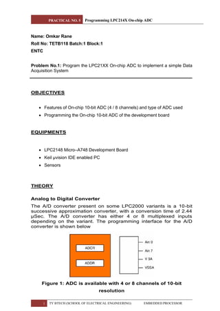
- 1. PRACTICAL NO. 5 Programming LPC214X On-chip ADC 1 TY BTECH (SCHOOL OF ELECTRICAL ENGINEERING) EMBEDDED PROCESSOR Name: Omkar Rane Roll No: TETB118 Batch:1 Block:1 ENTC Problem No.1: Program the LPC21XX On-chip ADC to implement a simple Data Acquisition System OBJECTIVES • Features of On-chip 10-bit ADC (4 / 8 channels) and type of ADC used • Programming the On-chip 10-bit ADC of the development board EQUIPMENTS • LPC2148 Micro–A748 Development Board • Keil µvision IDE enabled PC • Sensors THEORY Analog to Digital Converter The A/D converter present on some LPC2000 variants is a 10-bit successive approximation converter, with a conversion time of 2.44 µSec. The A/D converter has either 4 or 8 multiplexed inputs depending on the variant. The programming interface for the A/D converter is shown below Figure 1: ADC is available with 4 or 8 channels of 10-bit resolution
- 2. PRACTICAL NO. 5 Programming LPC214X On-chip ADC 2 TY BTECH (SCHOOL OF ELECTRICAL ENGINEERING) EMBEDDED PROCESSOR Features of ADC • 2 internal ADC's - ADC0 (6 Channel), ADC1 (8 Channel) • Type: 10-bit, Successive Approximation type, • Supports burst mode (repeated conversion at 3-bit to 10-bit resolution) • Supports simultaneous conversion on both ADC's • Conversion time: 2.44 micro-seconds • Start of Conversion by software control / on timer match /transition on a pin • Range: 0 V – VREF (+3.3 V) • Max. clock frequency is 4.5 MHz, (by programming ADC Control (ADxCON Register) ADC Control Registers: 1. SEL: The bits from (0 to 7) are used to select the channel for ADC conversion. One bit is allotted for each channel. For example setting the Bit-0 will make the ADC to sample AD0.1 for conversion. And setting the bit -1 will make AD0.1; similarly setting bit-7 will do the conversion for AD0.7. Important step is we have PINSEL according to the port we are using for example PINSEL0 for PORT0 in PLC2148. 2. CLCKDIV: The bits from (8 to 15) are for Clock Divisor. Here the APB clock (ARM Peripheral Bus clock) is divided by this value plus one to produce the clock required for the A/D converter, which should be less than or equal to 4.5 MHz as we are using successive approximation method in LPC2148. 3. BURST: The bit 16 is used for BURST conversion mode. Setting 1: The ADC will do the conversion for all the channels that are selected in SEL bits. Setting 0: Will disable the BURST conversion mode. 4. CLCKS: The bits from (17 to 19) three bits are used for selecting resolution and the number of clocks for A/D conversion in burst mode as it is continuous A/D conversion mode. 5. PDN: The bit 21 is for selecting Power down Mode of ADC in LPC2148. 1. A/D is in PDN mode. 2. A/D is in operational mode 6. START: The bits from (24 to 26) are for START. When the BURST conversion mode is OFF by setting 0, these START bits are useful for when to start the A/D conversion. The START is used for edge controlled conversion also. That is when there is an input in CAP or MAT pin of LPC2148 the A/D starts to convert. 7. EDGE: The 27th bit is for EDGE is used only when the START bit contains 010-111. It starts conversion when there is CAP or MAT input you can see above table for that. Setting: 0 - On Falling Edge 1- On Rising Edge
- 3. PRACTICAL NO. 5 Programming LPC214X On-chip ADC 3 TY BTECH (SCHOOL OF ELECTRICAL ENGINEERING) EMBEDDED PROCESSOR Configure ADC (AD0CR / AD1CR) Observations: Voltage Theoretical Values Practical Values ADC Hex Values 1.0 V 1/1024=9.7656 mV 1021 V 013D 1.5 V 1.5/1024=1.4648 mV 1591 V 01EE 2.0 V 2/1024=1.9531 mV 2072 V 0283 2.5 V 2.5/1024=2.4414 mV 2587 V 0329 3.0 V 3/1024=2.587 mV 3106 V 03C4 3.1 V 3.1/1024=3.027 mV 3229 V 03EA INTERFACING DETAILS / CONNECTIONS
- 4. PRACTICAL NO. 5 Programming LPC214X On-chip ADC 4 TY BTECH (SCHOOL OF ELECTRICAL ENGINEERING) EMBEDDED PROCESSOR ALGORITHM / FLOWCHART Steps for configuring the on-chip ADC 1. Configuring the ADC Power and ADC Port Pin 2. Configure ADC (AD0CR / AD1CR) 3. Reading the status of ADC 4. Reading the conversion results and displaying the Hex value on LCD display PROGRAM CODE adc_new.c file: #include "lpc214x.h" #include"stdio.h" #include"UART.h" #define ADC0 1<<24 #define ADC1 1<<26 #define ADC_ON 1<<21 #define ADC_Start 1<<24 #define ADC_Channel 0x03 #define ADC_Divider 0x03<<8 #define ADC_Burst 1<<16 #define ADC_CLKS 0x00<<17 void Display(int); void adcdelay(unsigned int time) { unsigned int i,j; for(i=0;i<time;i++) { for(j=0;j<10000;j++); } }
- 5. PRACTICAL NO. 5 Programming LPC214X On-chip ADC 5 TY BTECH (SCHOOL OF ELECTRICAL ENGINEERING) EMBEDDED PROCESSOR void ADCInit(void) { int i; i=PINSEL1; i=(i& 0xF0FFFFFF); PINSEL1=(i | (ADC0 | ADC1)); AD0CR=(ADC_Channel | ADC_Divider|ADC_Burst|ADC_CLKS); i=AD0CR; AD0CR=(i|ADC_ON); } unsigned int get_adc_voltage(unsigned int volt) { unsigned int volt_mv; volt_mv=((volt*3300)/1024); return volt_mv; } int main(void) { unsigned int ad0_data,ad1_data,voltage; unsigned char * String="ADC Value(hex)"; UartInit(9600); ADCInit(); //ADCInit(); printf("rn %s",String); while(1) { if(AD0STAT & 0x03) { ad1_data=(AD0DR1 & 0x0000FFC0)>>6; adcdelay(500); voltage=get_adc_voltage(ad1_data); printf("rnADC Voltage (mV)=%4d",voltage); Display(ad1_data); } return 0; } }
- 6. PRACTICAL NO. 5 Programming LPC214X On-chip ADC 6 TY BTECH (SCHOOL OF ELECTRICAL ENGINEERING) EMBEDDED PROCESSOR void Display(int v) { unsigned char Character[17]={"0123456789ABCDEF"}; unsigned char res[5]={"n"}; int i=0; unsigned int DivValue=0x1000,BaseValue=16; while(DivValue) { res[i]=Character[v/DivValue]; i++; v%=DivValue; DivValue/=BaseValue; } printf("rn ADC value in Hex = %s",res); UART_PutChar('n'); } Header File UART.h : void UartInit(unsigned int); int UART_PutChar(unsigned char); UART.c file: #include "lpc214x.h" #include "stdio.h" void UartInit(unsigned int baudrate) //setting the baud rate for 115200 baud { int i,FDiv; i = PINSEL0; // read the value of the pins function i = i & 0xFFFFFFF0; // modify the value PINSEL0 = (i | 0x05); // set the functionality of the TxD and Rxd Pin :01
- 7. PRACTICAL NO. 5 Programming LPC214X On-chip ADC 7 TY BTECH (SCHOOL OF ELECTRICAL ENGINEERING) EMBEDDED PROCESSOR //set the baud rate U0LCR = 0x83; // Line control register :DLAB=1 ; 8 bits ; 1 stop bit ; no parity FDiv = (15000000 / 16 ) / baudrate ; // U0DLM = FDiv /256; //0x00; U0DLL = FDiv %256; //0x97; U0LCR = 0x03; // Line control register :DLAB=0 ; 8 bits ; 1 stop bit ; no parity U0TER = 0x80; } int UART_GetChar(void) { while(!(U0LSR & 0x1)); return(U0RBR); } int UART_PutChar(unsigned char Ch) { if (Ch == 'n') { while (!(U0LSR & 0x20)); U0THR = 0x0D; /* output CR */ } while(!(U0LSR & 0x20)); return( U0THR = Ch); } int fputc(int ch, FILE *f) { return (UART_PutChar(ch)); } struct __FILE { int handle; /* Add whatever you need here */ }; FILE __stdout;
- 8. PRACTICAL NO. 5 Programming LPC214X On-chip ADC 8 TY BTECH (SCHOOL OF ELECTRICAL ENGINEERING) EMBEDDED PROCESSOR PROGRAM OUTPUT / RESULTS Host Machine and Target Board
- 9. PRACTICAL NO. 5 Programming LPC214X On-chip ADC 9 TY BTECH (SCHOOL OF ELECTRICAL ENGINEERING) EMBEDDED PROCESSOR
- 10. PRACTICAL NO. 5 Programming LPC214X On-chip ADC 10 TY BTECH (SCHOOL OF ELECTRICAL ENGINEERING) EMBEDDED PROCESSOR UART Readings On Host PC: 1.0 Volt 1.5 Volt
- 11. PRACTICAL NO. 5 Programming LPC214X On-chip ADC 11 TY BTECH (SCHOOL OF ELECTRICAL ENGINEERING) EMBEDDED PROCESSOR 2.0 Volt 2.5 Volt
- 12. PRACTICAL NO. 5 Programming LPC214X On-chip ADC 12 TY BTECH (SCHOOL OF ELECTRICAL ENGINEERING) EMBEDDED PROCESSOR 3.0 Volt 3.1 Volt ‘
- 13. PRACTICAL NO. 5 Programming LPC214X On-chip ADC 13 TY BTECH (SCHOOL OF ELECTRICAL ENGINEERING) EMBEDDED PROCESSOR REFERENCES 1. Andrew Sloss, Dominic Symes, Chris Wright, “ARM System Developer’s Guide – Designing and Optimizing System Software, ELSEVIER. 2. LPC 214x User manual (UM10139): www.nxp.com 3. ARM architecture reference manual: www.arm.com 4. Trevor Martin, “An Engineer’s Introduction to the LPC2100 series”, Hitex (UK) CONCLUSION In this experiment we studied about various registers in ADC on chip peripheral of LPC 2148 . We programmed them suitably to obtain respective results via UART . AD0.1 was given voltage between 0-3.1 V and voltage readings observed via UART on terminal screen. Theoretical and practical values almost same.