SlideShare una empresa de Scribd logo
1 de 21
Descargar para leer sin conexión
Paul Ahern - ie.linkedin.com/in/paulahern1
“Copper – Low-k Interconnect Technology Review” 1
Abstract
The one hallmark that typifies the evolution of integrated circuit technology
is the relentless move towards faster clock speeds and smaller geometries. The
foremost test facing chipmakers today is how to continue to drive this process
forward, extending Moore’s Law in the face of fundamental obstacles. The two
areas which are providing the biggest hurdles to IC manufacturing today (1) are
trying to scale lithography, and (2) scaling interconnect technology into the sub-22
nanometer range.
Figure 1 – Comparison between the front end transistor design for (a) 32nm and (b) 22nm process
nodes. The 22nm device employs a Tri-Gate transistor with multiple oxide “fins” positioned
perpendicularly to the substrate to deliver higher performance and lower power consumption
1
.
On the lithographic aspect, higher printing resolution and tighter spacing is
being achieved through the use of optical techniques such as phase shift masking,
immersion lithography and multiple-exposure pattering until preferred alternatives
such as extreme UV or electron-beam lithography are ready for mainstream usage.
At the 22nm process node we have for the first time entered a regimen where the
process node will not be dictated by the gate length, as 25nm gate lengths are
Paul Ahern - ie.linkedin.com/in/paulahern1
“Copper – Low-k Interconnect Technology Review” 2
typical, and also where the historic 2D planar design of transistor has been replaced
by a 3D “Tri-gate” design by companies such as Intel2
and AMD – with close to 3
billion transistors present on Intel’s Ivy bridge family of CPUs (see figure 1).
Meanwhile, on the interconnect side, the challenge is to adequately route
the signal into and out of the transistors in the device front-end while keeping pace
with increases in speed and packing density and also sidestepping the problems of
latency due to Resistive-Capacitive (RC) delay.
This review paper will focus on the development of interconnect technology,
from the SiO2 / aluminium system into the low-k/copper process node, and detail the
path forward for ever-shrinking process geometries which are fabricated for the first
time in all three dimensions.
From Aluminium to Copper
Aluminium has served the semiconductor industry well as a back-end metallisation
medium. Robert Noyce, then of Fairchild Semiconductor but later to be a co-founder
of Intel, filed his patent describing the “Semiconductor Device & Lead Structure3
”
approach in 1957. Noyce was the first to conceive using deposited aluminium metal
lines to connect transistors, diodes and other devices on the surface of a monolithic
piece of silicon, and aluminium remained the metallisation of choice up until the
0.18µm process node.
Aluminium can be deposited by Physical Vapour Deposition (PVD) or
Chemical Vapour Deposition (CVD) methods, giving a layer with sufficiently low
resistivity and good adherence to SiO2. Later, copper was added as an alloying
material in concentrations of up to 0.5 atomic percent, in order to improve the
electromigration lifetime of the conductor through the mechanisms of reduced
electron mobility and pinning defects at the grain boundaries4
.
Paul Ahern - ie.linkedin.com/in/paulahern1
“Copper – Low-k Interconnect Technology Review” 3
Figure 2 – (Left) SEM isometric view and (right) cross-section view of a 10 level copper metallised
integrated circuit
5
.
The 1994 edition of the pan-industry “National Technology Roadmap for
Semiconductors” (NTRS) was the first to focus on the upcoming need for new back-
end conductor materials and low-k dielectrics to satisfy the anticipated device
scaling and power requirements6
. As aluminium began to run out of steam, copper
was seen as its natural successor as an interconnect material due to its good
combination of material properties: high conductivity, low resistivity, ease of
deposition using the existing process methods, and having high electromigration
resistance.
There are also some inherent problems with copper such as its tendency to
corrode due to the absence of a self-passivating layer like that formed by aluminium,
and its questionable adhesion characteristics. In addition, new processing steps that
would be required to accommodate its inclusion in the fabrication process such as
damascene processing, electrochemical plating and chemical mechanical polishing
(CMP). Also, due to coppers tendency to diffuse into SiO2, cobalt or tungsten (and its
silicides) must be used instead of copper as the initial contact via layer where the
first metal layer connects into the transistor gate.
Paul Ahern - ie.linkedin.com/in/paulahern1
“Copper – Low-k Interconnect Technology Review” 4
Copper Patterning & the “Damascene” Methodology
One process change necessitated by the inclusion of copper as a back end metallic is
that dry etch processes, long utilised for aluminium, must be redesigned. These
subtractive etch chemistries are no longer viable with copper as the necessary etch
chemistries required cannot be generated within the acceptable thermal budget of
the fabrication process. Chemical Mechanical Polishing (CMP) is instead used to
planarise the surface of the wafer after copper has been laid down on the surface.
The term “damascening” has its roots in antiquity as a method for inlaying
patterned metals, typically gold or silver, into an object for purely aesthetic reasons.
In the world of integrated circuits, damascene is the process where copper layers are
patterned into an insulative substrate – dual damascene being where the vias and
the metal lines are deposited in one combined process step. A dual damascene
methodology has several advantages, such as its lower cost, lower via resistances
(due to the monolithic nature of the via-metal line stack), and faster processing time
with less process steps to monitor. Disadvantages are mainly due to the complexity
of controlling such a convoluted process and limitations on the aspect ratios that can
be filled by a one-step electroplating route7
.
Figure 3 – A diagrammatical representation of a standard “Via-First” dual-damascene process
8
.
Paul Ahern - ie.linkedin.com/in/paulahern1
“Copper – Low-k Interconnect Technology Review” 5
As shown in figure (3) previously, the via-first process starts at (a) with the
deposition of an interlayer dielectric (ILD). A photoresist layer is applied and
patterned in step (b) and the via structures are etched in step (c). After the resist
has been “ashed” or cleaned in step (d), another layer of resist is applied (e) which
patterns the locations for the metal lines. The lines are etched in step (f), with the
dark blue layer in the diagram representing a previously deposited embedded etch
stop layer which is usually composed of silicon nitride, the resist removed in step (g).
A barrier layer is applied in step (h) whose purpose is to promote adhesion of the
subsequent copper seed layer to the underlying ILD material and also to act as a
shunt layer to prevent electromigration. In step (i), copper fills the via/line trench
from the bottom up by a process of electroplating with additives, and in step (j) the
overhanging copper which is in excess from the electroplating process is planarised
back by a process of chemical mechanical polishing (CMP).
Deviations from Via-First Dual Damascene Processing
Variations on the via-first process are available: trench-first dual damascene
processing, as the name implies, flips the process so that the metal lines are
patterned first, the exposed resist layer removed, and then the remaining resist layer
is used to pattern the vias. The main disadvantage of this method is that via
lithography must be done on a resist surface which has already been cleaned and
can be quite rough. This results in slightly lower achievable minimum via sizes than
in the via-first scheme, meaning that below the 0.25µm process node the benefits of
a trench-first process are negligible9
.
Meanwhile, self-aligned (or “buried”) dual damascene is an interesting
variation which has not as yet found widespread acceptance in the semiconductor
manufacturing community. Patented by AMD in 199510
, the process works by
patterning the vias in the embedded etch stop layer before the second half of the ILD
is laid down with the trench pattern, and then both the via and trench are opened up
simultaneously with one etch step. While a perfectly controllable self-aligned
process would offer many advantages in terms of process simplification, the
disadvantages are that via-trench alignment is absolutely critical and misalignment
Paul Ahern - ie.linkedin.com/in/paulahern1
“Copper – Low-k Interconnect Technology Review” 6
can give vias which do not have a circular appearance, and also an etch process with
very high oxide:nitride selectivity is needed11
.
Interlayer Dielectrics Overview
The interlayer dielectric or “ILD” layer is used to insulate conductive metal
layers from one another to prevent shorting of the semiconductor device. As the
feature size of integrated circuits decreases into the nanometre range, the limiting
factor of integrated circuitry shifts from the traditional front-end attributes of gate
length and gate thickness, to back-end properties such as the conductivity of the
metal lines and interconnect layers, the parasitic capacitance and resistance of the
ILD materials, and the compatibility and mechanical properties of these new
materials. As such, low-k materials have a large part to play in the semiconductor
industries goal of extending Moore’s law for as long as feasibly possible.
Electrical Properties Mechanical Properties Thermal Properties
 Low dielectric constant
 Low dielectric loss
 Low leakage current
 No incorporated charges
 High reliability
 Good adhesion
 Low shrinkage
 Crack resistant
 Low film stress
 Sufficient hardness
 Thermal stability
 Low coefficient of
expansion
 Low shrinkage
 Sufficient heat
conductivity
Chemical Properties Processing Properties Metallisation Properties
 Resistant to acids and
bases
 High etch selectivity
 Low impurity levels
 No corrosion
 Low moisture uptake
 No outgassing
 Long storage life
 Environmentally safe
 Good Patternability
 Good gap fill
properties
 Good planarisation
uniformity
 Good deposition
uniformity
 Low pinhole rate
 Low particulate
count
 Low cost of
ownership
 Low metal temperature
 Compatible with
diffusion barriers
 Low contact resistance
 Good electromigration
performance
 Low level of stress
voiding
 Absence of hillock
formation
Figure 4 – An idealised “shopping list” of criteria which a successful ILD material must
demonstrate12
.
Paul Ahern - ie.linkedin.com/in/paulahern1
“Copper – Low-k Interconnect Technology Review” 7
The main reason that dielectric materials have come under the research
spotlight is due to their effect on device speed. At a process node size of 0.18µm
and above, the ILD layers acted as insulators but also provided important structural
support to the metal layers on the wafer. However, below the 180nm process node,
the intrinsic electrical and physical properties of the ILD material is much more
important13
. RC, or interconnect, delay now exceeds the gate delay of devices, and
its influence is even more prominent when the number of layers of metal lines, and
consequently the number of ILD layers, is increased. Resistance [R] can be
decreased by moving from aluminium to copper metallisation, and capacitance [C] is
reduced by the introduction of new ILD materials. Another concern is that, in order
to reduce dielectric heating, the capacitance must be further reduced by using
materials with a low dielectric constant (k) value – as high temperatures inside an
operating device can quickly lead to failure due to electromigration, diffusion of
implant regions and dielectric breakdown.
Type Interlayer Dielectric (ILD) materials Dielectric Constant (k)
Oxide Derivatives SiO2 3.9
SiOF (CVD) 3.5
Carbon doped oxide (CDO) films of
Hydrogen Silsesquioxane (HSD)
Methylsilsesquioxane (MSQ)
2.9 ~ 2.5
Organic Materials Fluoropolymide (spin-on) 2.8
Benzo-cyclo butene 2.7
Polyethylene 2.4
Polypropylene 2.3
Fluoropolymer 2.24
Parylene-F 2.2
PTFE (spun-on “Teflon”) 2.1 ~ 1.9
Highly Porous Oxides Aerogels & xerogels 2.5 ~ 1.8
Air 1
Figure 5 - Proposed CVD plasma deposited materials for future semiconductor fabrication
processes14
, 15
.
Paul Ahern - ie.linkedin.com/in/paulahern1
“Copper – Low-k Interconnect Technology Review” 8
Low-k Materials: Moving Beyond SiO2
Early contenders as a replacement for SiO2 were fluorine-based organic
polymers16
, SiO2-based inorganic oxides 17
and porous materials18
. Low-k dielectric
materials require some specific material properties as well as the prerequisite
electrical properties - these include the ability of the material to be deposited in a
low thermal budget scheme, to fill into narrow, deep metal layer interconnect gaps
without void formation, to be uniform in density to facilitation uniform planarisation
of the layer during chemical mechanical polishing (CMP) and have a high resistance
to moisture absorption from the atmosphere19
by possessing good barrier
hermeticity.
SiOF or FSG (Fluorinated Silicon Glass) became popular in the semiconductor
industry as it offered a rapid, step-wise integration into the standard SiO2 ILD regime,
and could be deposited using the standard PECVD or HDP-CVD deposition toolset.
The incorporation of Fluorine into amorphous SiO2 films reduces the film dielectric
constant and offers a film of high density and high thermal stability, and all this with
an appreciable decrease of the dielectric constant of the ILD layer from k  4 for SiO2
to k  3.5 for the plasma-deposited SiOF layers20
.
For all these reasons, doped ILD layers quickly became prevalent in any
semiconductor design where the patterning size was at or under 130nm where the
speed of signal propagation was important, giving a faster switching transistor device
with the added benefit of lower power consumption, with the added benefit of
reduced “cross-talk” between metal layers.
A further advantage was that the incorporation of fluorine into the ILD
introduced an etching character to the material during the deposition process. This
enhances the “gap-filling” capability of the film and allows metal lines with narrower
pitches to be conformally covered with a lesser instance of voiding. This allowed a
cost advantage as it resulted in more metal lines in a smaller area on the device
being fabricated21
.
The first wave of 180nm products that arrived at the end of 1999 contained
regular silica or fluorinated silicate glass (FSG) layers, with a range of dielectric
constant values between 3.7 and 4.2. The SiOF layers were deposited by various
Paul Ahern - ie.linkedin.com/in/paulahern1
“Copper – Low-k Interconnect Technology Review” 9
techniques such as PECVD using carbon fluorides, room temperature catalytic CVD
and electron cyclic resonance (ECR) plasma CVD. The announcement by IBM that it
was to pioneer Copper metallisation in its PowerPC 750 chip product increased
doubt in the industry about the readiness and need for low-k ILD layers. The modest
decrease in RC delay achieved by using copper only served to postpone the
development of the low-k materials by one process generation.
Migration to Carbon-Doped Oxides (CDO)
With the industry switching to copper metallisation, and 300mm wafer sizes
in order to take advantage of economies of scale, an opportunity presented itself to
usher in a new type of ILD material. At the time, the front-runner for next
generation 130nm process geometries was “SiLK”, a spin-on aromatic polymer
manufactured by Dow Chemical containing 60 at% Carbon, 39 at% Hydrogen and 1
at% Oxygen, but no Silicon. SiLK promised an attractive dielectric constant decrease
of k  2.7, but was expensive and required many complicated process tweaks to
integrate it, including mineral hard mask layers for polishing and adhesion reasons.
There were also reliability concerns with SiLK when integrated into a copper
metallisation scheme, with poor electromigration performance seen when compared
to the traditional Cu/SiO2 based regime.
Enter carbon–doped oxide (CDO), which built upon the fluorinated silicon
dioxide model and gave a more modest k decrease of 2.8 but crucially could be
deposited using well-understood plasma enhanced chemical vapour deposition (PE-
CVD) tools. The plasma processing initially left a damaged and strained film on the
wafer surface, but post-processing plasma treatments and thermal annealing
processes were developed that could be used to reduce these artefacts and give a
useable film22
.
Effect of Doping on the Dielectric Constant of SiO2
There are many theories as to the influence of doping on the dielectric constant of
SiO2. One or more of the following models may responsible for the decrease in k by
dopant species incorporation.
Paul Ahern - ie.linkedin.com/in/paulahern1
“Copper – Low-k Interconnect Technology Review” 10
Film Porosity: A model by Han23
and Aydil states that that incorporation of a dopant
species leads to a less dense, more porous film with controlled void formation.
Hydroxide Substitution: A model first proposed by Lim24
and co-workers that the
dopant displaces relatively more polarisable molecules such as SiOH in the film, thus
reducing the dielectric constant.
Silicon Oxide Bond Substitution: A model put forward by Shapiro25
and co-workers.
The belief is that Si-O bonds within the SiO2 matrix are replaced with Si-F bonds
which reduces the total polarisability of the matrix and hence lowers the electronic
contribution of the dielectric constant. Also, a further theory by Lim26
and co-
workers expands on this model with the idea that incorporation of Si-F or SiOF bonds
in the place of Si-O bonds reduces further the ionic character of the matrix and thus
the dielectric constant of the total film.
For carbon doped oxides, Ding & co-workers27
showed that an increase in the
cross-linking in the structure due to increased number of C-O and C-F bonds leads to
a lower observed dielectric constant value which varies strongly with the amount of
carbon and fluorine in the pre-cursor gases28
.
Process Control With Low-k Dielectrics
One of the challenges with carbon doped oxides concerns process control,
with many laboratory techniques used to control the electrical and mechanical
properties of the film. Dynamic Secondary-Ion Mass Spectroscopy (SIMS) is used to
monitor the carbon levels within the bulk of the film by depth profiling as well as the
crucial surface layers where carbon depletion can be an issue if the wafer is allowed
to sit under ambient pressure for too long. This can be remedied by the addition of
an adventitious surface layer of fluorocarbons on the carbon doped oxide surface by
varying the plasma chemistry to a slightly less oxygen-rich composition29
. Any post-
treatment needs to also monitor carefully any shrinkage in the film which could
adversely affect downstream lithographic steps in the process.
Paul Ahern - ie.linkedin.com/in/paulahern1
“Copper – Low-k Interconnect Technology Review” 11
Figure 6 – Some of the common process integration challenges involved in the Copper/low-k system
30
.
Moisture content and the rate of water uptake is a critical concern for low-k
dielectric films. A revealing study by Cheng et al31
showed that in FSG films (Fluoro-
Silicate Glass), the water absorption rate increases with increasing fluorine content.
High fluorine concentrations, which should give the lowest dielectric constant value,
are thus not utilised due to poor film stability as they absorb atmospheric water.
SiOF films with fluorine contents over 5 at% fluorine can expect to lose about 0.5 at%
after a week exposed in the cleanroom environment.
Moisture absorption and fluorine displacement increases rapidly for films
with higher at% F. Similarly, in carbon doped oxide films it was found that plasma
post-treatments usually lead to an increase in moisture uptake from the local
environment and a subsequent loss in carbon from the material due to substitution,
with the expected increase in k value32
.
For carbon doped oxides the presence of so-called “caged” SiO bonds in a
matrix composed of separate Si-O-Si and Si-O-C bonds has been put forward as being
responsible for the properties of the CDO film33
. Deliberately inducing pores into the
material allows a further decrease in the k value down to ~2.1.
Paul Ahern - ie.linkedin.com/in/paulahern1
“Copper – Low-k Interconnect Technology Review” 12
Interaction Between Low-k Dielectrics & Metal Layers / Oxides.
From the point of view of process control and integration, one of the most important
requirements is that the dopant from the low-k layer remain stationary and not
diffuse into other layers. This is difficult with SiOF as Fluorine is one of the most
mobile atoms; diffusion of F into metal layers will give rise to a corrosive interaction
with parts or all of the metal stack.
Work undertaken by Passemard and co-workers34
directly linked the level of
Fluorine to the level of corrosion in metal lines fabricated in a Ti/TiN/AlCu/TiN
regime. Visual inspection showed that below 3.4 at% Fluorine there was no
corrosion, but between 3.4 and 5 at% fluorine corrosion increased in the Ti/TiN
layers. Above 5 at% Fluorine the corrosion started to affect the AlCu layer also.
In all cases the corrosion begins at the outside edges of the metal lines.
In addition to this work, Choi and co-workers reported that the corrosion occurred in
the barrier layers (Ti and TiN) but not in the Al layers themselves35
. Labiadh’s
studies36
on Copper metal layers and SiOF dielectrics showed that there was no
diffusion from the SiOF into the copper layer or vice versa, but that F could be seen
in the Ti and TiN barrier layers.
Surmounting the Mechanical Adhesion Problem
One huge issue with the copper – low-k system is that the reliability and
robustness of the processing of such materials is strongly dependent on the
mechanical adhesion between layers in the back end of the process. While copper is
an improvement over aluminium in terms of its resistance, copper suffers from lower
adhesion compared to aluminium. This necessitates an understanding of its
behaviour in interaction with other materials it will come into contact with during
semiconductor processing37
.
Paul Ahern - ie.linkedin.com/in/paulahern1
“Copper – Low-k Interconnect Technology Review” 13
Figure 7 – SEM images showing the result of a four-point bending test on a carbon doped oxide –
copper IC. Sample (a) displays poor adhesion, sample (b) good adhesion. The crack dimensions can
be measured and used to understand the mechanisms for crack initiation & propagation
38
.
The mechanical adhesion and the dielectric constant of the film have an
inversely proportional relationship. Adhesion can be measured by four-point bend
testing to measure the dissipation of surface energy when a crack is propagated
along the CDO to copper interface, or it can be calculated from cross-sectional
nanoindentation39
of the film coupled with an understanding of its material
properties such as the Young’s Modulus. The dielectric constant can be measured by
using a standard four point probe, or by a more complicated mercury probe system
in which a blob of mercury is used as a temporary metal gate to form a parallel plate
capacitor system where conductance and K values can be read, usually in the form of
an “in-line” metrology step with the wafer fab. Targeting the K value too low leads
to issues with mechanical strength, film adhesion, low uniformity across the wafer
and voiding in the ILD film.
ILD Materials for 22nm Process Node & Below
The relentless march towards smaller feature sizes requires continued
materials & process research in order to forestall the much-mooted demise of
Moore’s Law. For low-k materials, the ability to continually reduce the intrinsic k
value of a monolithic thin film is becoming more and more challenging, and so the
easiest route seems to be the introduction of some porous character to existing
materials to further decrease RC delay. There are a huge number of potential
options being evaluated at present, with everything from porous silicate glass to
Paul Ahern - ie.linkedin.com/in/paulahern1
“Copper – Low-k Interconnect Technology Review” 14
aerogels being considered and piloted. It appears that the age of spin-on low-k
materials may have finally arrived after their shortcomings for carbon-doped oxides,
with porous SiLK now again being evaluated.
Many materials use some version of a sol-gel process to achieve a spin-on
material which is then exposed to a solvent to give an ordered, 3D network by
polymerisation and which has an easily-controlled pore size. Of critical importance
here is the distribution of pore sizes in the material, as a structure with open pores
and a wide variety of pore sizes will have poor mechanical strength rendering it
unusable in real-world processing conditions.
ATM Incorporated, in conjunction with fab equipment vendor ASM
International, have developed and patented40
the ability to produce porous, stable
carbon doped oxide films with k values of ~2 through a process of plasma-enhanced
CVD using precursors of cyclic siloxane and a pore-forming polymer species with a
thermally-cleavable organic group, termed a “porogen”. The porogen is a sacrificial
material which is then removed by UV curing to give a resultant film with adequate
mechanical strength, well-controlled pore size distribution and a pore fraction of
42% and a mean pore size of 3.3nm41
.
IBM, a long-standing leader in the low-k field, has shown details of their
solution, dubbed “post porosity plasma protection” or “P4” scheme. The film uses a
bridged oxy-carbosilane material which has open pores which are then charged with
an organic material prior to patterning and thermally removed at the end of the
process step. This solution is readily integrated with existing copper dual-damascene
processing and minimises Plasma-Induced Damage (PID) to the film which can be
caused by aggressive oxygen etch chemistries to porous materials.
Paul Ahern - ie.linkedin.com/in/paulahern1
“Copper – Low-k Interconnect Technology Review” 15
Figure 8 – IBM’s “P4” process, which stands for “Post Porosity Plasma Protection”, promises
a film with sufficient mechanical strength to withstand CMP. The filler material is then removed
afterwards to give open pores
42
.
The endgame for low-k materials is ultimately their elimination, replacing
them with a porous “air-gap” which will have a k value of ~1 and excellent reliability
in terms of enhanced gate leakage current, cross-talk and electromigration
performance. A major challenges is how to accurately self-align the air pocket
between the vias and trenches being patterned by the existing dual damascene
processing without the use of a mask layer. Conserving the mechanical integrity of
the device is also critical so that it can survive chemical-mechanical polishing and
adequately seal the internal air gaps to prevent any ingress of contamination.
To this end, many research groups43
are focussing on the use of some kind of
sacrificial material to form the air gap, and then once the copper lines have been
formed, this material can be completely removed to give aligned air cavities. The
main problem with this approach is that the overall thermal budget of the process
might not allow for the high-temperature processes needed to cleanly remove the
sacrificial material.
Paul Ahern - ie.linkedin.com/in/paulahern1
“Copper – Low-k Interconnect Technology Review” 16
Figure 9 – Cross-section diagram of how air gaps can be achieved in a dual damascene process.
Conventional carbon doped oxide (SiOC) is deposited and allowed to pinch closed at the opening at
the top of the metal trench, leaving an appreciable amount of ILD material for mechanical support
and to act as a chemical barrier layer
44
.
Copper Metallisation Beyond 22nm
The move towards air gaps brings with it a slew of challenges for the metallic parts of
the back-end process. Long-standing Chemical Vapour Deposition (CVD) methods
which have been successfully employed for decades, and even the relatively recent
Physical Vapour Deposition (PVD) techniques which were implemented at the 45nm
process node are suddenly faced with the possibility of being unable to fill the sub-
14nm metal trenches which are on the horizon. They require the deposition of
barrier layers which may be only 15Å, or three atomic layers, thick. Similarly, the
vast improvements that have been made in copper electroplating which have
allowed this technique to continue to be relevant, even at current process
geometries, must begin anew in order to keep pace with the need for highly
selective bottom-filling of vias and trenches of ever-smaller sizes.
Academia, equipment suppliers and the semiconductor industry has in turn
begun to look at new techniques such as Atomic Layer Deposition (ALD) coupled with
new metallic species to act as conductors. ALD allows for the deposition of
conformal layers which are only as thick as a single atom, in a very slow and
Paul Ahern - ie.linkedin.com/in/paulahern1
“Copper – Low-k Interconnect Technology Review” 17
controllable method, but it is thought that CVD may offer higher-purity films with
better conformal step-coverage.
Figure 10 – Diagram of an atomic layer deposition (ALD) process
45
. Very thin films can be laid down
by the successive use of a gas phase elemental deposition. The ultimate film thickness is governed by
the amount of ALD series, so thickness control is both precise and straightforward.
The currently-used Ta/TaN seed & barrier layer stack is likely to be replaced
with cobalt46
or ruthenium47
deposited by either ALD, CVD or a combination of both.
Ruthenium offers better wettability and adhesion with copper, but has poorer
polishing characteristics when it comes to CMP – conversely, cobalt is easier to
polish but is not an ideal barrier layer to stop the migration of oxygen, which means
long term reliability from corrosion and oxidation may suffer. Another issue is
electromigration performance48
, although cobalt would appear to offer advantages
here as a recent paper demonstrates49
. The authors show that cobalt films
deposited by CVD onto copper lines show a significant enhancement in
electromigration performance over time, which is critical as at smaller feature sizes
the gate region can be spanned and shorted by the presence of only a few atoms of
contamination.
Paul Ahern - ie.linkedin.com/in/paulahern1
“Copper – Low-k Interconnect Technology Review” 18
Figure 11 – Right
50
: Log scale of electromigration failure time comparing samples with & without a
cobalt capping layer. Left: Cross-section STEM image of a copper interconnect with cobalt cap. EDX
mapping below shows the distribution of tantalum, copper and cobalt in the via and its sidewalls.
Conclusion
Moving from aluminium to copper as an interconnect metal has provided many
advantages for semiconductor manufacturers, but has not been without its pitfalls.
New, complex process steps have been introduced in order to adapt the IC
manufacturing flow to accommodate copper and its characteristics; CMP, seed layer
deposition technology, improvements to electroplating bath chemistries and novel
etch steps have all been necessary. Improvements in low-k dielectric materials have
allowed the disruption of the inherent back-end speed bottleneck in semiconductor
devices to be mitigated. The result of even faster devices of smaller geometries have
extended Moore’s Law successfully for many process generations – however,
continual improvements are essential if the industry is to scale devices below the
crucial 22nm process node.
Paul Ahern - ie.linkedin.com/in/paulahern1
“Copper – Low-k Interconnect Technology Review” 19
References
1
M. Bohr & K. Mistry, “Intel’s Revolutionary 22nm Transistor Technology”
http://download.intel.com/newsroom/kits/22nm/pdfs/22nm-Details_Presentation.pdf; retrieved
21/11/2012.
2
M. Bohr & K. Mistry, ibid.
3
Noyce, Robert N., "Semiconductor Device-and-Lead Structure”, Reprint of U.S. Patent 2,981,877
(Issued April 25, 1961. Filed July 30, 1959), Solid-State Circuits Newsletter, IEEE, vol.12, no.2, pp.34-
40, (2007).
4
May, G.S. & Sze, S.M., “Fundamentals of Semiconductors Fabrication”, John Wiley & Sons (2004).
5
Edelstein, D. et al "Reliability, yield, and performance of a 90 nm SOI/Cu/SiCOH technology",
Proceedings of the IEEE 2004 International Interconnect Technology Conference, pp. 214- 216 (2004).
6
Rathore, H. S. & Chandra, K. “Chapter 4 - Copper, low-k dielectrics, and their reliability” from
“Semiconductor Manufacturing Handbook” editor Hwaiyu Geng, McGraw Hill (2005).
7
Dixit, G. A. & Havemann, R. H. “Overview of the Interconnect-Copper and Low-k Integration” chapter
from “Handbook of Semiconductor Manufacturing Technology, Second Edition” Edited by Robert
Doering and Yoshio Nishi, CRC Press (2007).
8
Weng, C. J. “Systematic defect improvement integration of dual damascene processes development
on nano semiconductor fabrication”, Materials Science in Semiconductor Processing, Vol. 13, Issues
5–6, pp. 376-382 (2010).
9
Wolf, S. “Introduction to dual-damascene interconnect processes” chapter from “Silicon Processing
for the VLSI era” Vol. 4 pp. 674-679, Lattice Press (2004).
10
US Patent Number 5,614,765 “Self-Aligned Via Dual Damascene” Avanzino et al.
http://www.google.co.uk/patents/US5614765, retrieved 3/12/2012.
11
Wolf, S. ibid.
12
After table presented in Semiconductor International Vol. 20 Issue 8 pp. 126 (1997).
13
May, G.S. & Sze, S.M., “Fundamentals of Semiconductors Fabrication”, John Wiley & Sons (2004).
14
After “The Future of Dielectric CVD High Density Plasmas”, Peter Singer, Semiconductor
International magazine (1997).
15
Saraswat, Prof. K. “Low-k Dielectrics” course notes, Dept. of Electrical Engineering, Stanford
University. http://www.stanford.edu/class/ee311/NOTES/Interconnect%20Lowk.pdf retreived
26/11/2012.
16
Muranka, S. P. “Fluorinted Silicon oxide glasses”, Solid State Technology, Vol. 38, pp. 83-88 (1996).
17
Fukuda, T. et al “Proceedings of the third international dielectrics for VLSI/ULSI Multilevel
Interconnection Conference” pp. 41 (1997).
18
Hendricks, N. H. “Solid State Technology” Vol. 38 pp. 117 (1995).
19
Kalkman, A.J. et al “SiOF and SiO2 deposition in an ECR-HDP reactor: Tool characterisation and film
analysis”, Microelectronic Engineering Vol. 37/38pp. 271-276 (1997).
Paul Ahern - ie.linkedin.com/in/paulahern1
“Copper – Low-k Interconnect Technology Review” 20
20
Reynard, J. "Integration of fluorine-doped silicon oxide in copper pilot line for 0.12-μm technology".
Microelectronic Engineering, Vol. 60, 113 (2002)
21
Homma, T. “Fluorinated interlayer dielectric films in ULSI multilevel interconnections” , Journal of
Non-crystalline Solids, Vol. 187 pp. 49-59 (1995).
22
Wang, Y. H. et al, Electrochemical & Solid-State Letters, Vol. 6, F1 (2003).
23
Han, S. M. & Aydil, E. S., Journal of Vacuum Science & Technology (A), Vol. 15 pp. 2893 (1997).
24
Lim, S. W. et al, Journal of Electrochemistry Society, Vol. 144 pp. 2531 (1997).
25
Shapiro, M. J. et al, Journal of Thin Solid Films, Vol. 270 pp. 503 (1995).
26
Lim, S. W. et al, Japan Journal of Applied Physics, Vol. 35 pp. 1468 (1996).
27
Wang, P.F. et al “An amorphous SiCOF film with low dielectric constant prepared by plasma-
enhanced chemical vapor deposition”, Thin Solid Films, Vol. 385, pp. 115-119 (2001).
28
Ding, S.J. et al “Structure characterization of carbon and fluorine-doped silicon oxide films with low
dielectric constant”, Materials Chemistry & Physics, Vol. 71, Issue 2, pp. 125-130 (2001).
29
I. Reid et al, “Suppression of carbon depletion from carbon-doped low-k dielectric layers during
fluorocarbon-based plasma etching” Microelectronic Engineering Vol. 83, Issues 11–12, pp. 2458–
2461 (2006).
30
Jan, C.H., IEDM Short Course (2003).
31
Cheng, Y. L. et al “Characterization and reliability of low dielectric constant fluorosilicate glass and
silicon rich oxide process for deep sub-micron device application” Thin Solid Films, Vol. 398 – 399 pp.
533–538 (2001).
32
Wangz, Y. H. & Kumar, R. “Stability of Carbon-Doped Silicon Oxide Low-k Thin Films” J. Electrochem.
Soc. Vol. 151, Issue 4, F73-F76 (2004).
33
Yang, C.S. et al “The influence of carbon content in carbon-doped silicon oxide film by thermal
treatment”, Thin Solid Films, Vol. 435, Issues 1–2, pp. 165-169 (2003).
34
Passemard, G. et al “Study of fluorine stability in fluoro-silicate glass and effects on dielectric
properties”, Microelectronic Engineering, Vol. 33, pp. 335-342 (1997).
35
Choi, J. H. et al “IEEE VMIC Conference Reports”, pp. 397 (1995).
36
Labiadh, A. “Study of the thermal stability at the Cu/SiOF interface”, Microelectronic Engineering,
Vol. 33, Issues 1-4 pp. 369-375 (1997).
37
Felder, Eric et al “Characterization of the adhesion of thin film by Cross-Sectional Nanoindentation
Analysis of the substrate edge chipping and the film delamination” Comptes Rendus Mecanique, Vol.
339, pp. 443 – 457 (2011).
38
Molina-Aldareguia, J.M. et al “Adhesion studies in integrated circuit interconnect structures”,
Engineering Failure Analysis, Vol. 14, Issue 2, pp. 349-354 (2007).
Paul Ahern - ie.linkedin.com/in/paulahern1
“Copper – Low-k Interconnect Technology Review” 21
39
Sánchez, J.M. et al “Cross-sectional nanoindentation: a new technique for thin film interfacial
adhesion characterization”, Acta Materialia, Vol. 47, Issue 17, pp. 4405-4413 (1999).
40
Xu, C. “Porogen Material for ultralow-k dielectrics” US Patent Number 7,456,488 B2,
http://assignments.uspto.gov/assignments/q?db=pat&pat=7456488 retrieved 27/11/2012.
41
LaPedus, M. “Challenges Mount For Interconnects” Semiconductor Manufacturing & Design,
http://semimd.com/blog/2012/06/26/challenges-mount-for-interconnect/, retrieved 27/11/2012.
42
Frot, T. et al “Post Porosity Plasma Protection - a new approach to integrate k ≤ 2.2 porous ULK
materials” Interconnect Technology Conference & 2011 Materials for Advanced Metallization
(IITC/MAM), IEEE International (2011).
43
Gosset, L. G. et al “General review of issues and perspectives for advanced copper interconnections
using air gap as ultra-low K material”. Proceedings of the IEEE 2003 International Interconnect
Technology Conference (2003).
44
Korczynski, E. “IEDM Shows Air-gaps By Design” news article on Semiconductor Manufacturing &
Design, http://semimd.com/blog/2011/02/05/iedm-2010-shows-air-gaps-for-real/ retrieved
26/11/2012.
45
Wang, H. et al, "Atomic Layer Deposition of Lanthanum-Based Ternary Oxides," Electrochemical &
Solid-State Letters Vol. 12 (4), G13-G15 (2009).
46
Kim, H. et al “Applications of atomic layer deposition to nanofabrication and emerging
nanodevices”, Thin Solid Films, Vol. 517, Issue 8, pp. 2563-2580 (2009).
47
Gebregziabiher, D. K. et al “Electrochemical atomic layer deposition of copper nanofilms on
ruthenium”, Journal of Crystal Growth, Vol. 312, Issue 8, pp. 1271-1276 (2010).
48
Yang, C.-C. et al "Characterization of Copper Electromigration Dependence on Selective Chemical
Vapor Deposited Cobalt Capping Layer Thickness," Electron Device Letters, IEEE , Vol.32, no.4, pp.560-
562 (2011).
49
Yang, C.-C. et al, “Co capping layers for Cu/low-k interconnects”, Microelectronic Engineering, Vol.
92, pp. 79-82 (2012).
50
Yang, C.-C. et al, ibid.

Más contenido relacionado

La actualidad más candente

Vlsi design and fabrication ppt
Vlsi design and fabrication  pptVlsi design and fabrication  ppt
Vlsi design and fabrication pptManjushree Mashal
 
Reactive ion etching (RIE)
Reactive ion etching (RIE)Reactive ion etching (RIE)
Reactive ion etching (RIE)SumanKundu40
 
Lithography, Photolithography--ABU SYED KUET
Lithography, Photolithography--ABU SYED KUETLithography, Photolithography--ABU SYED KUET
Lithography, Photolithography--ABU SYED KUETA. S. M. Jannatul Islam
 
High k dielectrics
High k dielectricsHigh k dielectrics
High k dielectricsSubash John
 
Ellipsometry- non destructive measuring method
Ellipsometry- non destructive measuring methodEllipsometry- non destructive measuring method
Ellipsometry- non destructive measuring methodViji Vijitha
 
Vlsi assembly technology
Vlsi  assembly technologyVlsi  assembly technology
Vlsi assembly technologyAshu0711
 
Band structure and surface properties of 1-4 layers of MoS2
Band structure and surface properties of 1-4 layers of MoS2Band structure and surface properties of 1-4 layers of MoS2
Band structure and surface properties of 1-4 layers of MoS2Po-Chun Yeh
 
Extreme uv lithography
Extreme uv lithographyExtreme uv lithography
Extreme uv lithographyZUNAIR ARSLAN
 
Heterostructures, HBTs and Thyristors : Exploring the "different"
Heterostructures, HBTs and Thyristors : Exploring the "different"Heterostructures, HBTs and Thyristors : Exploring the "different"
Heterostructures, HBTs and Thyristors : Exploring the "different"Shuvan Prashant
 
Laser diode fabrication
Laser diode fabricationLaser diode fabrication
Laser diode fabricationuttam999
 
Dielectric materials
Dielectric materialsDielectric materials
Dielectric materialsFarkhandaAna
 
Zinc oxide thin film
Zinc oxide thin filmZinc oxide thin film
Zinc oxide thin filmNavyaprajith
 

La actualidad más candente (20)

Vlsi design and fabrication ppt
Vlsi design and fabrication  pptVlsi design and fabrication  ppt
Vlsi design and fabrication ppt
 
CNTFET
CNTFETCNTFET
CNTFET
 
Reactive ion etching (RIE)
Reactive ion etching (RIE)Reactive ion etching (RIE)
Reactive ion etching (RIE)
 
ESD protection
ESD protection ESD protection
ESD protection
 
Lithography, Photolithography--ABU SYED KUET
Lithography, Photolithography--ABU SYED KUETLithography, Photolithography--ABU SYED KUET
Lithography, Photolithography--ABU SYED KUET
 
High k dielectrics
High k dielectricsHigh k dielectrics
High k dielectrics
 
Rosh ppt
Rosh pptRosh ppt
Rosh ppt
 
Ellipsometry- non destructive measuring method
Ellipsometry- non destructive measuring methodEllipsometry- non destructive measuring method
Ellipsometry- non destructive measuring method
 
Laser soldering
Laser solderingLaser soldering
Laser soldering
 
BULK METALLIC GLASS
BULK METALLIC GLASSBULK METALLIC GLASS
BULK METALLIC GLASS
 
Vlsi assembly technology
Vlsi  assembly technologyVlsi  assembly technology
Vlsi assembly technology
 
Band structure and surface properties of 1-4 layers of MoS2
Band structure and surface properties of 1-4 layers of MoS2Band structure and surface properties of 1-4 layers of MoS2
Band structure and surface properties of 1-4 layers of MoS2
 
Extreme uv lithography
Extreme uv lithographyExtreme uv lithography
Extreme uv lithography
 
Heterostructures, HBTs and Thyristors : Exploring the "different"
Heterostructures, HBTs and Thyristors : Exploring the "different"Heterostructures, HBTs and Thyristors : Exploring the "different"
Heterostructures, HBTs and Thyristors : Exploring the "different"
 
METAMATERIALS
METAMATERIALSMETAMATERIALS
METAMATERIALS
 
3dchips
3dchips3dchips
3dchips
 
Laser diode fabrication
Laser diode fabricationLaser diode fabrication
Laser diode fabrication
 
Perovskite
PerovskitePerovskite
Perovskite
 
Dielectric materials
Dielectric materialsDielectric materials
Dielectric materials
 
Zinc oxide thin film
Zinc oxide thin filmZinc oxide thin film
Zinc oxide thin film
 

Destacado

Globalfoundries, DAC 2011 Update
Globalfoundries, DAC 2011 UpdateGlobalfoundries, DAC 2011 Update
Globalfoundries, DAC 2011 UpdateMarketing EDA
 
Dfm dem prospectus
Dfm dem prospectusDfm dem prospectus
Dfm dem prospectusMedvarsity
 
45nm Product Press Briefing
45nm Product Press Briefing45nm Product Press Briefing
45nm Product Press Briefingangsikod
 
Intel 45nm high-k metal-gate press release
Intel 45nm high-k metal-gate press releaseIntel 45nm high-k metal-gate press release
Intel 45nm high-k metal-gate press releaseangsikod
 
Issm 2010-po-o-102 ppt-for_cdrom_final_revised
Issm 2010-po-o-102 ppt-for_cdrom_final_revisedIssm 2010-po-o-102 ppt-for_cdrom_final_revised
Issm 2010-po-o-102 ppt-for_cdrom_final_revisedSidewinder2011
 
HIGH-K DEVICES BY ALD FOR SEMICONDUCTOR APPLICATIONS
HIGH-K DEVICES BY ALD FOR SEMICONDUCTOR APPLICATIONSHIGH-K DEVICES BY ALD FOR SEMICONDUCTOR APPLICATIONS
HIGH-K DEVICES BY ALD FOR SEMICONDUCTOR APPLICATIONSJonas Sundqvist
 
45nm Summary Foils
45nm Summary Foils45nm Summary Foils
45nm Summary Foilsangsikod
 
45nm transistor properties
45nm transistor properties45nm transistor properties
45nm transistor propertiesDeiptii Das
 
Physical Design Flow Challenges at 28nm on Multi-million Gate Blocks
Physical Design Flow Challenges at 28nm on Multi-million Gate BlocksPhysical Design Flow Challenges at 28nm on Multi-million Gate Blocks
Physical Design Flow Challenges at 28nm on Multi-million Gate BlockseInfochips (An Arrow Company)
 
半導體製程
半導體製程半導體製程
半導體製程zhchenwin
 
3D or Tri-gate transistors
3D or Tri-gate transistors3D or Tri-gate transistors
3D or Tri-gate transistorsKaranvir Singh
 
Process of Semiconductor Manufacturing
Process of Semiconductor ManufacturingProcess of Semiconductor Manufacturing
Process of Semiconductor ManufacturingWAFER WORLD, INC
 
intel PDF 32nm Technology Update Mark Bohr
intel  PDF  	32nm Technology Update Mark Bohrintel  PDF  	32nm Technology Update Mark Bohr
intel PDF 32nm Technology Update Mark Bohrfinance6
 

Destacado (20)

Globalfoundries, DAC 2011 Update
Globalfoundries, DAC 2011 UpdateGlobalfoundries, DAC 2011 Update
Globalfoundries, DAC 2011 Update
 
Dfm dem prospectus
Dfm dem prospectusDfm dem prospectus
Dfm dem prospectus
 
45nm Product Press Briefing
45nm Product Press Briefing45nm Product Press Briefing
45nm Product Press Briefing
 
Intel 45nm high-k metal-gate press release
Intel 45nm high-k metal-gate press releaseIntel 45nm high-k metal-gate press release
Intel 45nm high-k metal-gate press release
 
Issm 2010-po-o-102 ppt-for_cdrom_final_revised
Issm 2010-po-o-102 ppt-for_cdrom_final_revisedIssm 2010-po-o-102 ppt-for_cdrom_final_revised
Issm 2010-po-o-102 ppt-for_cdrom_final_revised
 
HIGH-K DEVICES BY ALD FOR SEMICONDUCTOR APPLICATIONS
HIGH-K DEVICES BY ALD FOR SEMICONDUCTOR APPLICATIONSHIGH-K DEVICES BY ALD FOR SEMICONDUCTOR APPLICATIONS
HIGH-K DEVICES BY ALD FOR SEMICONDUCTOR APPLICATIONS
 
45nm Summary Foils
45nm Summary Foils45nm Summary Foils
45nm Summary Foils
 
High k dielectric
High k dielectricHigh k dielectric
High k dielectric
 
45nm transistor properties
45nm transistor properties45nm transistor properties
45nm transistor properties
 
Physical Design Flow Challenges at 28nm on Multi-million Gate Blocks
Physical Design Flow Challenges at 28nm on Multi-million Gate BlocksPhysical Design Flow Challenges at 28nm on Multi-million Gate Blocks
Physical Design Flow Challenges at 28nm on Multi-million Gate Blocks
 
Metal oxide semiconductor
Metal oxide semiconductorMetal oxide semiconductor
Metal oxide semiconductor
 
半導體製程
半導體製程半導體製程
半導體製程
 
Sushant
SushantSushant
Sushant
 
50 years of Moore's Law.
50 years of Moore's Law.50 years of Moore's Law.
50 years of Moore's Law.
 
tri gate transistors
tri gate transistorstri gate transistors
tri gate transistors
 
3D or Tri-gate transistors
3D or Tri-gate transistors3D or Tri-gate transistors
3D or Tri-gate transistors
 
Process of Semiconductor Manufacturing
Process of Semiconductor ManufacturingProcess of Semiconductor Manufacturing
Process of Semiconductor Manufacturing
 
FET FOR DIPLOMA
FET FOR DIPLOMAFET FOR DIPLOMA
FET FOR DIPLOMA
 
intel PDF 32nm Technology Update Mark Bohr
intel  PDF  	32nm Technology Update Mark Bohrintel  PDF  	32nm Technology Update Mark Bohr
intel PDF 32nm Technology Update Mark Bohr
 
3d transistor
3d transistor3d transistor
3d transistor
 

Similar a Copper interconnect and low-k dielectrics for sub-22nm chips

Metallization
Metallization Metallization
Metallization GKGanesh2
 
Planarized, Extendible, Multilayer Fabrication
Planarized, Extendible, Multilayer FabricationPlanarized, Extendible, Multilayer Fabrication
Planarized, Extendible, Multilayer FabricationAlexander Cohen
 
(cathodic protection)
(cathodic protection) (cathodic protection)
(cathodic protection) Mohamed Safwat
 
Welcome to International Journal of Engineering Research and Development (IJERD)
Welcome to International Journal of Engineering Research and Development (IJERD)Welcome to International Journal of Engineering Research and Development (IJERD)
Welcome to International Journal of Engineering Research and Development (IJERD)IJERD Editor
 
MOSFET, SOI-FET and FIN-FET-ABU SYED KUET
MOSFET, SOI-FET and FIN-FET-ABU SYED KUETMOSFET, SOI-FET and FIN-FET-ABU SYED KUET
MOSFET, SOI-FET and FIN-FET-ABU SYED KUETA. S. M. Jannatul Islam
 
EDL2003_RF power silicon-on-glass VDMOSFET
EDL2003_RF power silicon-on-glass VDMOSFETEDL2003_RF power silicon-on-glass VDMOSFET
EDL2003_RF power silicon-on-glass VDMOSFETSteven Theeuwen
 
Dielectric Q-V Measurements using COS technique
Dielectric Q-V Measurements using COS techniqueDielectric Q-V Measurements using COS technique
Dielectric Q-V Measurements using COS techniqueMichael Shifrin
 
Electrical characterization of semiconductor-insulator interfaces in VLSI:ULS...
Electrical characterization of semiconductor-insulator interfaces in VLSI:ULS...Electrical characterization of semiconductor-insulator interfaces in VLSI:ULS...
Electrical characterization of semiconductor-insulator interfaces in VLSI:ULS...Dang Trang
 
Micro-alloyed copper overhead line conductors - Wire & Cable Technology Inter...
Micro-alloyed copper overhead line conductors - Wire & Cable Technology Inter...Micro-alloyed copper overhead line conductors - Wire & Cable Technology Inter...
Micro-alloyed copper overhead line conductors - Wire & Cable Technology Inter...Leonardo ENERGY
 
MSE PhD lecture. Adv. Mater. Synthesis. Thin Films. Oct 23, 2014.
MSE PhD lecture. Adv. Mater. Synthesis. Thin Films. Oct 23, 2014.MSE PhD lecture. Adv. Mater. Synthesis. Thin Films. Oct 23, 2014.
MSE PhD lecture. Adv. Mater. Synthesis. Thin Films. Oct 23, 2014.Toru Hara
 
Mse phd lecture
Mse phd lectureMse phd lecture
Mse phd lectureToru Hara
 
Introduction_to_Electroforming
Introduction_to_ElectroformingIntroduction_to_Electroforming
Introduction_to_ElectroformingKathleen Stillman
 
Basic Multilayer PCB Manufacturing Training Module
Basic Multilayer PCB Manufacturing Training ModuleBasic Multilayer PCB Manufacturing Training Module
Basic Multilayer PCB Manufacturing Training ModuleKimBilugan
 
Axios bridge final-english
Axios bridge  final-englishAxios bridge  final-english
Axios bridge final-englishChris Rodopoulos
 

Similar a Copper interconnect and low-k dielectrics for sub-22nm chips (20)

Pvc cmos finale
Pvc cmos finale Pvc cmos finale
Pvc cmos finale
 
Metallization
Metallization Metallization
Metallization
 
Planarized, Extendible, Multilayer Fabrication
Planarized, Extendible, Multilayer FabricationPlanarized, Extendible, Multilayer Fabrication
Planarized, Extendible, Multilayer Fabrication
 
(cathodic protection)
(cathodic protection) (cathodic protection)
(cathodic protection)
 
Welcome to International Journal of Engineering Research and Development (IJERD)
Welcome to International Journal of Engineering Research and Development (IJERD)Welcome to International Journal of Engineering Research and Development (IJERD)
Welcome to International Journal of Engineering Research and Development (IJERD)
 
MOSFET, SOI-FET and FIN-FET-ABU SYED KUET
MOSFET, SOI-FET and FIN-FET-ABU SYED KUETMOSFET, SOI-FET and FIN-FET-ABU SYED KUET
MOSFET, SOI-FET and FIN-FET-ABU SYED KUET
 
EDL2003_RF power silicon-on-glass VDMOSFET
EDL2003_RF power silicon-on-glass VDMOSFETEDL2003_RF power silicon-on-glass VDMOSFET
EDL2003_RF power silicon-on-glass VDMOSFET
 
cmos_steps.ppt
cmos_steps.pptcmos_steps.ppt
cmos_steps.ppt
 
2220 2447-1-pb
2220 2447-1-pb2220 2447-1-pb
2220 2447-1-pb
 
Analog vlsi
Analog vlsiAnalog vlsi
Analog vlsi
 
Dielectric Q-V Measurements using COS technique
Dielectric Q-V Measurements using COS techniqueDielectric Q-V Measurements using COS technique
Dielectric Q-V Measurements using COS technique
 
eDRAM-Crolles_2005
eDRAM-Crolles_2005eDRAM-Crolles_2005
eDRAM-Crolles_2005
 
Electrical characterization of semiconductor-insulator interfaces in VLSI:ULS...
Electrical characterization of semiconductor-insulator interfaces in VLSI:ULS...Electrical characterization of semiconductor-insulator interfaces in VLSI:ULS...
Electrical characterization of semiconductor-insulator interfaces in VLSI:ULS...
 
Micro-alloyed copper overhead line conductors - Wire & Cable Technology Inter...
Micro-alloyed copper overhead line conductors - Wire & Cable Technology Inter...Micro-alloyed copper overhead line conductors - Wire & Cable Technology Inter...
Micro-alloyed copper overhead line conductors - Wire & Cable Technology Inter...
 
MSE PhD lecture. Adv. Mater. Synthesis. Thin Films. Oct 23, 2014.
MSE PhD lecture. Adv. Mater. Synthesis. Thin Films. Oct 23, 2014.MSE PhD lecture. Adv. Mater. Synthesis. Thin Films. Oct 23, 2014.
MSE PhD lecture. Adv. Mater. Synthesis. Thin Films. Oct 23, 2014.
 
Mse phd lecture
Mse phd lectureMse phd lecture
Mse phd lecture
 
Introduction_to_Electroforming
Introduction_to_ElectroformingIntroduction_to_Electroforming
Introduction_to_Electroforming
 
Basic Multilayer PCB Manufacturing Training Module
Basic Multilayer PCB Manufacturing Training ModuleBasic Multilayer PCB Manufacturing Training Module
Basic Multilayer PCB Manufacturing Training Module
 
Axios bridge final-english
Axios bridge  final-englishAxios bridge  final-english
Axios bridge final-english
 
High k dielectric
High k dielectricHigh k dielectric
High k dielectric
 

Último

Call Girls In Sikandarpur Gurgaon ❤️8860477959_Russian 100% Genuine Escorts I...
Call Girls In Sikandarpur Gurgaon ❤️8860477959_Russian 100% Genuine Escorts I...Call Girls In Sikandarpur Gurgaon ❤️8860477959_Russian 100% Genuine Escorts I...
Call Girls In Sikandarpur Gurgaon ❤️8860477959_Russian 100% Genuine Escorts I...lizamodels9
 
Call Girls In Connaught Place Delhi ❤️88604**77959_Russian 100% Genuine Escor...
Call Girls In Connaught Place Delhi ❤️88604**77959_Russian 100% Genuine Escor...Call Girls In Connaught Place Delhi ❤️88604**77959_Russian 100% Genuine Escor...
Call Girls In Connaught Place Delhi ❤️88604**77959_Russian 100% Genuine Escor...lizamodels9
 
Case study on tata clothing brand zudio in detail
Case study on tata clothing brand zudio in detailCase study on tata clothing brand zudio in detail
Case study on tata clothing brand zudio in detailAriel592675
 
Innovation Conference 5th March 2024.pdf
Innovation Conference 5th March 2024.pdfInnovation Conference 5th March 2024.pdf
Innovation Conference 5th March 2024.pdfrichard876048
 
Call US-88OO1O2216 Call Girls In Mahipalpur Female Escort Service
Call US-88OO1O2216 Call Girls In Mahipalpur Female Escort ServiceCall US-88OO1O2216 Call Girls In Mahipalpur Female Escort Service
Call US-88OO1O2216 Call Girls In Mahipalpur Female Escort Servicecallgirls2057
 
Ten Organizational Design Models to align structure and operations to busines...
Ten Organizational Design Models to align structure and operations to busines...Ten Organizational Design Models to align structure and operations to busines...
Ten Organizational Design Models to align structure and operations to busines...Seta Wicaksana
 
MAHA Global and IPR: Do Actions Speak Louder Than Words?
MAHA Global and IPR: Do Actions Speak Louder Than Words?MAHA Global and IPR: Do Actions Speak Louder Than Words?
MAHA Global and IPR: Do Actions Speak Louder Than Words?Olivia Kresic
 
Lowrate Call Girls In Sector 18 Noida ❤️8860477959 Escorts 100% Genuine Servi...
Lowrate Call Girls In Sector 18 Noida ❤️8860477959 Escorts 100% Genuine Servi...Lowrate Call Girls In Sector 18 Noida ❤️8860477959 Escorts 100% Genuine Servi...
Lowrate Call Girls In Sector 18 Noida ❤️8860477959 Escorts 100% Genuine Servi...lizamodels9
 
8447779800, Low rate Call girls in Uttam Nagar Delhi NCR
8447779800, Low rate Call girls in Uttam Nagar Delhi NCR8447779800, Low rate Call girls in Uttam Nagar Delhi NCR
8447779800, Low rate Call girls in Uttam Nagar Delhi NCRashishs7044
 
Marketplace and Quality Assurance Presentation - Vincent Chirchir
Marketplace and Quality Assurance Presentation - Vincent ChirchirMarketplace and Quality Assurance Presentation - Vincent Chirchir
Marketplace and Quality Assurance Presentation - Vincent Chirchirictsugar
 
8447779800, Low rate Call girls in Kotla Mubarakpur Delhi NCR
8447779800, Low rate Call girls in Kotla Mubarakpur Delhi NCR8447779800, Low rate Call girls in Kotla Mubarakpur Delhi NCR
8447779800, Low rate Call girls in Kotla Mubarakpur Delhi NCRashishs7044
 
Contemporary Economic Issues Facing the Filipino Entrepreneur (1).pptx
Contemporary Economic Issues Facing the Filipino Entrepreneur (1).pptxContemporary Economic Issues Facing the Filipino Entrepreneur (1).pptx
Contemporary Economic Issues Facing the Filipino Entrepreneur (1).pptxMarkAnthonyAurellano
 
8447779800, Low rate Call girls in Shivaji Enclave Delhi NCR
8447779800, Low rate Call girls in Shivaji Enclave Delhi NCR8447779800, Low rate Call girls in Shivaji Enclave Delhi NCR
8447779800, Low rate Call girls in Shivaji Enclave Delhi NCRashishs7044
 
Intro to BCG's Carbon Emissions Benchmark_vF.pdf
Intro to BCG's Carbon Emissions Benchmark_vF.pdfIntro to BCG's Carbon Emissions Benchmark_vF.pdf
Intro to BCG's Carbon Emissions Benchmark_vF.pdfpollardmorgan
 
8447779800, Low rate Call girls in Saket Delhi NCR
8447779800, Low rate Call girls in Saket Delhi NCR8447779800, Low rate Call girls in Saket Delhi NCR
8447779800, Low rate Call girls in Saket Delhi NCRashishs7044
 
APRIL2024_UKRAINE_xml_0000000000000 .pdf
APRIL2024_UKRAINE_xml_0000000000000 .pdfAPRIL2024_UKRAINE_xml_0000000000000 .pdf
APRIL2024_UKRAINE_xml_0000000000000 .pdfRbc Rbcua
 
Flow Your Strategy at Flight Levels Day 2024
Flow Your Strategy at Flight Levels Day 2024Flow Your Strategy at Flight Levels Day 2024
Flow Your Strategy at Flight Levels Day 2024Kirill Klimov
 
Call Girls Miyapur 7001305949 all area service COD available Any Time
Call Girls Miyapur 7001305949 all area service COD available Any TimeCall Girls Miyapur 7001305949 all area service COD available Any Time
Call Girls Miyapur 7001305949 all area service COD available Any Timedelhimodelshub1
 
2024 Numerator Consumer Study of Cannabis Usage
2024 Numerator Consumer Study of Cannabis Usage2024 Numerator Consumer Study of Cannabis Usage
2024 Numerator Consumer Study of Cannabis UsageNeil Kimberley
 

Último (20)

Call Girls In Sikandarpur Gurgaon ❤️8860477959_Russian 100% Genuine Escorts I...
Call Girls In Sikandarpur Gurgaon ❤️8860477959_Russian 100% Genuine Escorts I...Call Girls In Sikandarpur Gurgaon ❤️8860477959_Russian 100% Genuine Escorts I...
Call Girls In Sikandarpur Gurgaon ❤️8860477959_Russian 100% Genuine Escorts I...
 
Call Girls In Connaught Place Delhi ❤️88604**77959_Russian 100% Genuine Escor...
Call Girls In Connaught Place Delhi ❤️88604**77959_Russian 100% Genuine Escor...Call Girls In Connaught Place Delhi ❤️88604**77959_Russian 100% Genuine Escor...
Call Girls In Connaught Place Delhi ❤️88604**77959_Russian 100% Genuine Escor...
 
Case study on tata clothing brand zudio in detail
Case study on tata clothing brand zudio in detailCase study on tata clothing brand zudio in detail
Case study on tata clothing brand zudio in detail
 
Innovation Conference 5th March 2024.pdf
Innovation Conference 5th March 2024.pdfInnovation Conference 5th March 2024.pdf
Innovation Conference 5th March 2024.pdf
 
Call US-88OO1O2216 Call Girls In Mahipalpur Female Escort Service
Call US-88OO1O2216 Call Girls In Mahipalpur Female Escort ServiceCall US-88OO1O2216 Call Girls In Mahipalpur Female Escort Service
Call US-88OO1O2216 Call Girls In Mahipalpur Female Escort Service
 
Ten Organizational Design Models to align structure and operations to busines...
Ten Organizational Design Models to align structure and operations to busines...Ten Organizational Design Models to align structure and operations to busines...
Ten Organizational Design Models to align structure and operations to busines...
 
Japan IT Week 2024 Brochure by 47Billion (English)
Japan IT Week 2024 Brochure by 47Billion (English)Japan IT Week 2024 Brochure by 47Billion (English)
Japan IT Week 2024 Brochure by 47Billion (English)
 
MAHA Global and IPR: Do Actions Speak Louder Than Words?
MAHA Global and IPR: Do Actions Speak Louder Than Words?MAHA Global and IPR: Do Actions Speak Louder Than Words?
MAHA Global and IPR: Do Actions Speak Louder Than Words?
 
Lowrate Call Girls In Sector 18 Noida ❤️8860477959 Escorts 100% Genuine Servi...
Lowrate Call Girls In Sector 18 Noida ❤️8860477959 Escorts 100% Genuine Servi...Lowrate Call Girls In Sector 18 Noida ❤️8860477959 Escorts 100% Genuine Servi...
Lowrate Call Girls In Sector 18 Noida ❤️8860477959 Escorts 100% Genuine Servi...
 
8447779800, Low rate Call girls in Uttam Nagar Delhi NCR
8447779800, Low rate Call girls in Uttam Nagar Delhi NCR8447779800, Low rate Call girls in Uttam Nagar Delhi NCR
8447779800, Low rate Call girls in Uttam Nagar Delhi NCR
 
Marketplace and Quality Assurance Presentation - Vincent Chirchir
Marketplace and Quality Assurance Presentation - Vincent ChirchirMarketplace and Quality Assurance Presentation - Vincent Chirchir
Marketplace and Quality Assurance Presentation - Vincent Chirchir
 
8447779800, Low rate Call girls in Kotla Mubarakpur Delhi NCR
8447779800, Low rate Call girls in Kotla Mubarakpur Delhi NCR8447779800, Low rate Call girls in Kotla Mubarakpur Delhi NCR
8447779800, Low rate Call girls in Kotla Mubarakpur Delhi NCR
 
Contemporary Economic Issues Facing the Filipino Entrepreneur (1).pptx
Contemporary Economic Issues Facing the Filipino Entrepreneur (1).pptxContemporary Economic Issues Facing the Filipino Entrepreneur (1).pptx
Contemporary Economic Issues Facing the Filipino Entrepreneur (1).pptx
 
8447779800, Low rate Call girls in Shivaji Enclave Delhi NCR
8447779800, Low rate Call girls in Shivaji Enclave Delhi NCR8447779800, Low rate Call girls in Shivaji Enclave Delhi NCR
8447779800, Low rate Call girls in Shivaji Enclave Delhi NCR
 
Intro to BCG's Carbon Emissions Benchmark_vF.pdf
Intro to BCG's Carbon Emissions Benchmark_vF.pdfIntro to BCG's Carbon Emissions Benchmark_vF.pdf
Intro to BCG's Carbon Emissions Benchmark_vF.pdf
 
8447779800, Low rate Call girls in Saket Delhi NCR
8447779800, Low rate Call girls in Saket Delhi NCR8447779800, Low rate Call girls in Saket Delhi NCR
8447779800, Low rate Call girls in Saket Delhi NCR
 
APRIL2024_UKRAINE_xml_0000000000000 .pdf
APRIL2024_UKRAINE_xml_0000000000000 .pdfAPRIL2024_UKRAINE_xml_0000000000000 .pdf
APRIL2024_UKRAINE_xml_0000000000000 .pdf
 
Flow Your Strategy at Flight Levels Day 2024
Flow Your Strategy at Flight Levels Day 2024Flow Your Strategy at Flight Levels Day 2024
Flow Your Strategy at Flight Levels Day 2024
 
Call Girls Miyapur 7001305949 all area service COD available Any Time
Call Girls Miyapur 7001305949 all area service COD available Any TimeCall Girls Miyapur 7001305949 all area service COD available Any Time
Call Girls Miyapur 7001305949 all area service COD available Any Time
 
2024 Numerator Consumer Study of Cannabis Usage
2024 Numerator Consumer Study of Cannabis Usage2024 Numerator Consumer Study of Cannabis Usage
2024 Numerator Consumer Study of Cannabis Usage
 

Copper interconnect and low-k dielectrics for sub-22nm chips

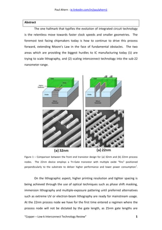
  • 1. Paul Ahern - ie.linkedin.com/in/paulahern1 “Copper – Low-k Interconnect Technology Review” 1 Abstract The one hallmark that typifies the evolution of integrated circuit technology is the relentless move towards faster clock speeds and smaller geometries. The foremost test facing chipmakers today is how to continue to drive this process forward, extending Moore’s Law in the face of fundamental obstacles. The two areas which are providing the biggest hurdles to IC manufacturing today (1) are trying to scale lithography, and (2) scaling interconnect technology into the sub-22 nanometer range. Figure 1 – Comparison between the front end transistor design for (a) 32nm and (b) 22nm process nodes. The 22nm device employs a Tri-Gate transistor with multiple oxide “fins” positioned perpendicularly to the substrate to deliver higher performance and lower power consumption 1 . On the lithographic aspect, higher printing resolution and tighter spacing is being achieved through the use of optical techniques such as phase shift masking, immersion lithography and multiple-exposure pattering until preferred alternatives such as extreme UV or electron-beam lithography are ready for mainstream usage. At the 22nm process node we have for the first time entered a regimen where the process node will not be dictated by the gate length, as 25nm gate lengths are
  • 2. Paul Ahern - ie.linkedin.com/in/paulahern1 “Copper – Low-k Interconnect Technology Review” 2 typical, and also where the historic 2D planar design of transistor has been replaced by a 3D “Tri-gate” design by companies such as Intel2 and AMD – with close to 3 billion transistors present on Intel’s Ivy bridge family of CPUs (see figure 1). Meanwhile, on the interconnect side, the challenge is to adequately route the signal into and out of the transistors in the device front-end while keeping pace with increases in speed and packing density and also sidestepping the problems of latency due to Resistive-Capacitive (RC) delay. This review paper will focus on the development of interconnect technology, from the SiO2 / aluminium system into the low-k/copper process node, and detail the path forward for ever-shrinking process geometries which are fabricated for the first time in all three dimensions. From Aluminium to Copper Aluminium has served the semiconductor industry well as a back-end metallisation medium. Robert Noyce, then of Fairchild Semiconductor but later to be a co-founder of Intel, filed his patent describing the “Semiconductor Device & Lead Structure3 ” approach in 1957. Noyce was the first to conceive using deposited aluminium metal lines to connect transistors, diodes and other devices on the surface of a monolithic piece of silicon, and aluminium remained the metallisation of choice up until the 0.18µm process node. Aluminium can be deposited by Physical Vapour Deposition (PVD) or Chemical Vapour Deposition (CVD) methods, giving a layer with sufficiently low resistivity and good adherence to SiO2. Later, copper was added as an alloying material in concentrations of up to 0.5 atomic percent, in order to improve the electromigration lifetime of the conductor through the mechanisms of reduced electron mobility and pinning defects at the grain boundaries4 .
  • 3. Paul Ahern - ie.linkedin.com/in/paulahern1 “Copper – Low-k Interconnect Technology Review” 3 Figure 2 – (Left) SEM isometric view and (right) cross-section view of a 10 level copper metallised integrated circuit 5 . The 1994 edition of the pan-industry “National Technology Roadmap for Semiconductors” (NTRS) was the first to focus on the upcoming need for new back- end conductor materials and low-k dielectrics to satisfy the anticipated device scaling and power requirements6 . As aluminium began to run out of steam, copper was seen as its natural successor as an interconnect material due to its good combination of material properties: high conductivity, low resistivity, ease of deposition using the existing process methods, and having high electromigration resistance. There are also some inherent problems with copper such as its tendency to corrode due to the absence of a self-passivating layer like that formed by aluminium, and its questionable adhesion characteristics. In addition, new processing steps that would be required to accommodate its inclusion in the fabrication process such as damascene processing, electrochemical plating and chemical mechanical polishing (CMP). Also, due to coppers tendency to diffuse into SiO2, cobalt or tungsten (and its silicides) must be used instead of copper as the initial contact via layer where the first metal layer connects into the transistor gate.
  • 4. Paul Ahern - ie.linkedin.com/in/paulahern1 “Copper – Low-k Interconnect Technology Review” 4 Copper Patterning & the “Damascene” Methodology One process change necessitated by the inclusion of copper as a back end metallic is that dry etch processes, long utilised for aluminium, must be redesigned. These subtractive etch chemistries are no longer viable with copper as the necessary etch chemistries required cannot be generated within the acceptable thermal budget of the fabrication process. Chemical Mechanical Polishing (CMP) is instead used to planarise the surface of the wafer after copper has been laid down on the surface. The term “damascening” has its roots in antiquity as a method for inlaying patterned metals, typically gold or silver, into an object for purely aesthetic reasons. In the world of integrated circuits, damascene is the process where copper layers are patterned into an insulative substrate – dual damascene being where the vias and the metal lines are deposited in one combined process step. A dual damascene methodology has several advantages, such as its lower cost, lower via resistances (due to the monolithic nature of the via-metal line stack), and faster processing time with less process steps to monitor. Disadvantages are mainly due to the complexity of controlling such a convoluted process and limitations on the aspect ratios that can be filled by a one-step electroplating route7 . Figure 3 – A diagrammatical representation of a standard “Via-First” dual-damascene process 8 .
  • 5. Paul Ahern - ie.linkedin.com/in/paulahern1 “Copper – Low-k Interconnect Technology Review” 5 As shown in figure (3) previously, the via-first process starts at (a) with the deposition of an interlayer dielectric (ILD). A photoresist layer is applied and patterned in step (b) and the via structures are etched in step (c). After the resist has been “ashed” or cleaned in step (d), another layer of resist is applied (e) which patterns the locations for the metal lines. The lines are etched in step (f), with the dark blue layer in the diagram representing a previously deposited embedded etch stop layer which is usually composed of silicon nitride, the resist removed in step (g). A barrier layer is applied in step (h) whose purpose is to promote adhesion of the subsequent copper seed layer to the underlying ILD material and also to act as a shunt layer to prevent electromigration. In step (i), copper fills the via/line trench from the bottom up by a process of electroplating with additives, and in step (j) the overhanging copper which is in excess from the electroplating process is planarised back by a process of chemical mechanical polishing (CMP). Deviations from Via-First Dual Damascene Processing Variations on the via-first process are available: trench-first dual damascene processing, as the name implies, flips the process so that the metal lines are patterned first, the exposed resist layer removed, and then the remaining resist layer is used to pattern the vias. The main disadvantage of this method is that via lithography must be done on a resist surface which has already been cleaned and can be quite rough. This results in slightly lower achievable minimum via sizes than in the via-first scheme, meaning that below the 0.25µm process node the benefits of a trench-first process are negligible9 . Meanwhile, self-aligned (or “buried”) dual damascene is an interesting variation which has not as yet found widespread acceptance in the semiconductor manufacturing community. Patented by AMD in 199510 , the process works by patterning the vias in the embedded etch stop layer before the second half of the ILD is laid down with the trench pattern, and then both the via and trench are opened up simultaneously with one etch step. While a perfectly controllable self-aligned process would offer many advantages in terms of process simplification, the disadvantages are that via-trench alignment is absolutely critical and misalignment
  • 6. Paul Ahern - ie.linkedin.com/in/paulahern1 “Copper – Low-k Interconnect Technology Review” 6 can give vias which do not have a circular appearance, and also an etch process with very high oxide:nitride selectivity is needed11 . Interlayer Dielectrics Overview The interlayer dielectric or “ILD” layer is used to insulate conductive metal layers from one another to prevent shorting of the semiconductor device. As the feature size of integrated circuits decreases into the nanometre range, the limiting factor of integrated circuitry shifts from the traditional front-end attributes of gate length and gate thickness, to back-end properties such as the conductivity of the metal lines and interconnect layers, the parasitic capacitance and resistance of the ILD materials, and the compatibility and mechanical properties of these new materials. As such, low-k materials have a large part to play in the semiconductor industries goal of extending Moore’s law for as long as feasibly possible. Electrical Properties Mechanical Properties Thermal Properties  Low dielectric constant  Low dielectric loss  Low leakage current  No incorporated charges  High reliability  Good adhesion  Low shrinkage  Crack resistant  Low film stress  Sufficient hardness  Thermal stability  Low coefficient of expansion  Low shrinkage  Sufficient heat conductivity Chemical Properties Processing Properties Metallisation Properties  Resistant to acids and bases  High etch selectivity  Low impurity levels  No corrosion  Low moisture uptake  No outgassing  Long storage life  Environmentally safe  Good Patternability  Good gap fill properties  Good planarisation uniformity  Good deposition uniformity  Low pinhole rate  Low particulate count  Low cost of ownership  Low metal temperature  Compatible with diffusion barriers  Low contact resistance  Good electromigration performance  Low level of stress voiding  Absence of hillock formation Figure 4 – An idealised “shopping list” of criteria which a successful ILD material must demonstrate12 .
  • 7. Paul Ahern - ie.linkedin.com/in/paulahern1 “Copper – Low-k Interconnect Technology Review” 7 The main reason that dielectric materials have come under the research spotlight is due to their effect on device speed. At a process node size of 0.18µm and above, the ILD layers acted as insulators but also provided important structural support to the metal layers on the wafer. However, below the 180nm process node, the intrinsic electrical and physical properties of the ILD material is much more important13 . RC, or interconnect, delay now exceeds the gate delay of devices, and its influence is even more prominent when the number of layers of metal lines, and consequently the number of ILD layers, is increased. Resistance [R] can be decreased by moving from aluminium to copper metallisation, and capacitance [C] is reduced by the introduction of new ILD materials. Another concern is that, in order to reduce dielectric heating, the capacitance must be further reduced by using materials with a low dielectric constant (k) value – as high temperatures inside an operating device can quickly lead to failure due to electromigration, diffusion of implant regions and dielectric breakdown. Type Interlayer Dielectric (ILD) materials Dielectric Constant (k) Oxide Derivatives SiO2 3.9 SiOF (CVD) 3.5 Carbon doped oxide (CDO) films of Hydrogen Silsesquioxane (HSD) Methylsilsesquioxane (MSQ) 2.9 ~ 2.5 Organic Materials Fluoropolymide (spin-on) 2.8 Benzo-cyclo butene 2.7 Polyethylene 2.4 Polypropylene 2.3 Fluoropolymer 2.24 Parylene-F 2.2 PTFE (spun-on “Teflon”) 2.1 ~ 1.9 Highly Porous Oxides Aerogels & xerogels 2.5 ~ 1.8 Air 1 Figure 5 - Proposed CVD plasma deposited materials for future semiconductor fabrication processes14 , 15 .
  • 8. Paul Ahern - ie.linkedin.com/in/paulahern1 “Copper – Low-k Interconnect Technology Review” 8 Low-k Materials: Moving Beyond SiO2 Early contenders as a replacement for SiO2 were fluorine-based organic polymers16 , SiO2-based inorganic oxides 17 and porous materials18 . Low-k dielectric materials require some specific material properties as well as the prerequisite electrical properties - these include the ability of the material to be deposited in a low thermal budget scheme, to fill into narrow, deep metal layer interconnect gaps without void formation, to be uniform in density to facilitation uniform planarisation of the layer during chemical mechanical polishing (CMP) and have a high resistance to moisture absorption from the atmosphere19 by possessing good barrier hermeticity. SiOF or FSG (Fluorinated Silicon Glass) became popular in the semiconductor industry as it offered a rapid, step-wise integration into the standard SiO2 ILD regime, and could be deposited using the standard PECVD or HDP-CVD deposition toolset. The incorporation of Fluorine into amorphous SiO2 films reduces the film dielectric constant and offers a film of high density and high thermal stability, and all this with an appreciable decrease of the dielectric constant of the ILD layer from k  4 for SiO2 to k  3.5 for the plasma-deposited SiOF layers20 . For all these reasons, doped ILD layers quickly became prevalent in any semiconductor design where the patterning size was at or under 130nm where the speed of signal propagation was important, giving a faster switching transistor device with the added benefit of lower power consumption, with the added benefit of reduced “cross-talk” between metal layers. A further advantage was that the incorporation of fluorine into the ILD introduced an etching character to the material during the deposition process. This enhances the “gap-filling” capability of the film and allows metal lines with narrower pitches to be conformally covered with a lesser instance of voiding. This allowed a cost advantage as it resulted in more metal lines in a smaller area on the device being fabricated21 . The first wave of 180nm products that arrived at the end of 1999 contained regular silica or fluorinated silicate glass (FSG) layers, with a range of dielectric constant values between 3.7 and 4.2. The SiOF layers were deposited by various
  • 9. Paul Ahern - ie.linkedin.com/in/paulahern1 “Copper – Low-k Interconnect Technology Review” 9 techniques such as PECVD using carbon fluorides, room temperature catalytic CVD and electron cyclic resonance (ECR) plasma CVD. The announcement by IBM that it was to pioneer Copper metallisation in its PowerPC 750 chip product increased doubt in the industry about the readiness and need for low-k ILD layers. The modest decrease in RC delay achieved by using copper only served to postpone the development of the low-k materials by one process generation. Migration to Carbon-Doped Oxides (CDO) With the industry switching to copper metallisation, and 300mm wafer sizes in order to take advantage of economies of scale, an opportunity presented itself to usher in a new type of ILD material. At the time, the front-runner for next generation 130nm process geometries was “SiLK”, a spin-on aromatic polymer manufactured by Dow Chemical containing 60 at% Carbon, 39 at% Hydrogen and 1 at% Oxygen, but no Silicon. SiLK promised an attractive dielectric constant decrease of k  2.7, but was expensive and required many complicated process tweaks to integrate it, including mineral hard mask layers for polishing and adhesion reasons. There were also reliability concerns with SiLK when integrated into a copper metallisation scheme, with poor electromigration performance seen when compared to the traditional Cu/SiO2 based regime. Enter carbon–doped oxide (CDO), which built upon the fluorinated silicon dioxide model and gave a more modest k decrease of 2.8 but crucially could be deposited using well-understood plasma enhanced chemical vapour deposition (PE- CVD) tools. The plasma processing initially left a damaged and strained film on the wafer surface, but post-processing plasma treatments and thermal annealing processes were developed that could be used to reduce these artefacts and give a useable film22 . Effect of Doping on the Dielectric Constant of SiO2 There are many theories as to the influence of doping on the dielectric constant of SiO2. One or more of the following models may responsible for the decrease in k by dopant species incorporation.
  • 10. Paul Ahern - ie.linkedin.com/in/paulahern1 “Copper – Low-k Interconnect Technology Review” 10 Film Porosity: A model by Han23 and Aydil states that that incorporation of a dopant species leads to a less dense, more porous film with controlled void formation. Hydroxide Substitution: A model first proposed by Lim24 and co-workers that the dopant displaces relatively more polarisable molecules such as SiOH in the film, thus reducing the dielectric constant. Silicon Oxide Bond Substitution: A model put forward by Shapiro25 and co-workers. The belief is that Si-O bonds within the SiO2 matrix are replaced with Si-F bonds which reduces the total polarisability of the matrix and hence lowers the electronic contribution of the dielectric constant. Also, a further theory by Lim26 and co- workers expands on this model with the idea that incorporation of Si-F or SiOF bonds in the place of Si-O bonds reduces further the ionic character of the matrix and thus the dielectric constant of the total film. For carbon doped oxides, Ding & co-workers27 showed that an increase in the cross-linking in the structure due to increased number of C-O and C-F bonds leads to a lower observed dielectric constant value which varies strongly with the amount of carbon and fluorine in the pre-cursor gases28 . Process Control With Low-k Dielectrics One of the challenges with carbon doped oxides concerns process control, with many laboratory techniques used to control the electrical and mechanical properties of the film. Dynamic Secondary-Ion Mass Spectroscopy (SIMS) is used to monitor the carbon levels within the bulk of the film by depth profiling as well as the crucial surface layers where carbon depletion can be an issue if the wafer is allowed to sit under ambient pressure for too long. This can be remedied by the addition of an adventitious surface layer of fluorocarbons on the carbon doped oxide surface by varying the plasma chemistry to a slightly less oxygen-rich composition29 . Any post- treatment needs to also monitor carefully any shrinkage in the film which could adversely affect downstream lithographic steps in the process.
  • 11. Paul Ahern - ie.linkedin.com/in/paulahern1 “Copper – Low-k Interconnect Technology Review” 11 Figure 6 – Some of the common process integration challenges involved in the Copper/low-k system 30 . Moisture content and the rate of water uptake is a critical concern for low-k dielectric films. A revealing study by Cheng et al31 showed that in FSG films (Fluoro- Silicate Glass), the water absorption rate increases with increasing fluorine content. High fluorine concentrations, which should give the lowest dielectric constant value, are thus not utilised due to poor film stability as they absorb atmospheric water. SiOF films with fluorine contents over 5 at% fluorine can expect to lose about 0.5 at% after a week exposed in the cleanroom environment. Moisture absorption and fluorine displacement increases rapidly for films with higher at% F. Similarly, in carbon doped oxide films it was found that plasma post-treatments usually lead to an increase in moisture uptake from the local environment and a subsequent loss in carbon from the material due to substitution, with the expected increase in k value32 . For carbon doped oxides the presence of so-called “caged” SiO bonds in a matrix composed of separate Si-O-Si and Si-O-C bonds has been put forward as being responsible for the properties of the CDO film33 . Deliberately inducing pores into the material allows a further decrease in the k value down to ~2.1.
  • 12. Paul Ahern - ie.linkedin.com/in/paulahern1 “Copper – Low-k Interconnect Technology Review” 12 Interaction Between Low-k Dielectrics & Metal Layers / Oxides. From the point of view of process control and integration, one of the most important requirements is that the dopant from the low-k layer remain stationary and not diffuse into other layers. This is difficult with SiOF as Fluorine is one of the most mobile atoms; diffusion of F into metal layers will give rise to a corrosive interaction with parts or all of the metal stack. Work undertaken by Passemard and co-workers34 directly linked the level of Fluorine to the level of corrosion in metal lines fabricated in a Ti/TiN/AlCu/TiN regime. Visual inspection showed that below 3.4 at% Fluorine there was no corrosion, but between 3.4 and 5 at% fluorine corrosion increased in the Ti/TiN layers. Above 5 at% Fluorine the corrosion started to affect the AlCu layer also. In all cases the corrosion begins at the outside edges of the metal lines. In addition to this work, Choi and co-workers reported that the corrosion occurred in the barrier layers (Ti and TiN) but not in the Al layers themselves35 . Labiadh’s studies36 on Copper metal layers and SiOF dielectrics showed that there was no diffusion from the SiOF into the copper layer or vice versa, but that F could be seen in the Ti and TiN barrier layers. Surmounting the Mechanical Adhesion Problem One huge issue with the copper – low-k system is that the reliability and robustness of the processing of such materials is strongly dependent on the mechanical adhesion between layers in the back end of the process. While copper is an improvement over aluminium in terms of its resistance, copper suffers from lower adhesion compared to aluminium. This necessitates an understanding of its behaviour in interaction with other materials it will come into contact with during semiconductor processing37 .
  • 13. Paul Ahern - ie.linkedin.com/in/paulahern1 “Copper – Low-k Interconnect Technology Review” 13 Figure 7 – SEM images showing the result of a four-point bending test on a carbon doped oxide – copper IC. Sample (a) displays poor adhesion, sample (b) good adhesion. The crack dimensions can be measured and used to understand the mechanisms for crack initiation & propagation 38 . The mechanical adhesion and the dielectric constant of the film have an inversely proportional relationship. Adhesion can be measured by four-point bend testing to measure the dissipation of surface energy when a crack is propagated along the CDO to copper interface, or it can be calculated from cross-sectional nanoindentation39 of the film coupled with an understanding of its material properties such as the Young’s Modulus. The dielectric constant can be measured by using a standard four point probe, or by a more complicated mercury probe system in which a blob of mercury is used as a temporary metal gate to form a parallel plate capacitor system where conductance and K values can be read, usually in the form of an “in-line” metrology step with the wafer fab. Targeting the K value too low leads to issues with mechanical strength, film adhesion, low uniformity across the wafer and voiding in the ILD film. ILD Materials for 22nm Process Node & Below The relentless march towards smaller feature sizes requires continued materials & process research in order to forestall the much-mooted demise of Moore’s Law. For low-k materials, the ability to continually reduce the intrinsic k value of a monolithic thin film is becoming more and more challenging, and so the easiest route seems to be the introduction of some porous character to existing materials to further decrease RC delay. There are a huge number of potential options being evaluated at present, with everything from porous silicate glass to
  • 14. Paul Ahern - ie.linkedin.com/in/paulahern1 “Copper – Low-k Interconnect Technology Review” 14 aerogels being considered and piloted. It appears that the age of spin-on low-k materials may have finally arrived after their shortcomings for carbon-doped oxides, with porous SiLK now again being evaluated. Many materials use some version of a sol-gel process to achieve a spin-on material which is then exposed to a solvent to give an ordered, 3D network by polymerisation and which has an easily-controlled pore size. Of critical importance here is the distribution of pore sizes in the material, as a structure with open pores and a wide variety of pore sizes will have poor mechanical strength rendering it unusable in real-world processing conditions. ATM Incorporated, in conjunction with fab equipment vendor ASM International, have developed and patented40 the ability to produce porous, stable carbon doped oxide films with k values of ~2 through a process of plasma-enhanced CVD using precursors of cyclic siloxane and a pore-forming polymer species with a thermally-cleavable organic group, termed a “porogen”. The porogen is a sacrificial material which is then removed by UV curing to give a resultant film with adequate mechanical strength, well-controlled pore size distribution and a pore fraction of 42% and a mean pore size of 3.3nm41 . IBM, a long-standing leader in the low-k field, has shown details of their solution, dubbed “post porosity plasma protection” or “P4” scheme. The film uses a bridged oxy-carbosilane material which has open pores which are then charged with an organic material prior to patterning and thermally removed at the end of the process step. This solution is readily integrated with existing copper dual-damascene processing and minimises Plasma-Induced Damage (PID) to the film which can be caused by aggressive oxygen etch chemistries to porous materials.
  • 15. Paul Ahern - ie.linkedin.com/in/paulahern1 “Copper – Low-k Interconnect Technology Review” 15 Figure 8 – IBM’s “P4” process, which stands for “Post Porosity Plasma Protection”, promises a film with sufficient mechanical strength to withstand CMP. The filler material is then removed afterwards to give open pores 42 . The endgame for low-k materials is ultimately their elimination, replacing them with a porous “air-gap” which will have a k value of ~1 and excellent reliability in terms of enhanced gate leakage current, cross-talk and electromigration performance. A major challenges is how to accurately self-align the air pocket between the vias and trenches being patterned by the existing dual damascene processing without the use of a mask layer. Conserving the mechanical integrity of the device is also critical so that it can survive chemical-mechanical polishing and adequately seal the internal air gaps to prevent any ingress of contamination. To this end, many research groups43 are focussing on the use of some kind of sacrificial material to form the air gap, and then once the copper lines have been formed, this material can be completely removed to give aligned air cavities. The main problem with this approach is that the overall thermal budget of the process might not allow for the high-temperature processes needed to cleanly remove the sacrificial material.
  • 16. Paul Ahern - ie.linkedin.com/in/paulahern1 “Copper – Low-k Interconnect Technology Review” 16 Figure 9 – Cross-section diagram of how air gaps can be achieved in a dual damascene process. Conventional carbon doped oxide (SiOC) is deposited and allowed to pinch closed at the opening at the top of the metal trench, leaving an appreciable amount of ILD material for mechanical support and to act as a chemical barrier layer 44 . Copper Metallisation Beyond 22nm The move towards air gaps brings with it a slew of challenges for the metallic parts of the back-end process. Long-standing Chemical Vapour Deposition (CVD) methods which have been successfully employed for decades, and even the relatively recent Physical Vapour Deposition (PVD) techniques which were implemented at the 45nm process node are suddenly faced with the possibility of being unable to fill the sub- 14nm metal trenches which are on the horizon. They require the deposition of barrier layers which may be only 15Å, or three atomic layers, thick. Similarly, the vast improvements that have been made in copper electroplating which have allowed this technique to continue to be relevant, even at current process geometries, must begin anew in order to keep pace with the need for highly selective bottom-filling of vias and trenches of ever-smaller sizes. Academia, equipment suppliers and the semiconductor industry has in turn begun to look at new techniques such as Atomic Layer Deposition (ALD) coupled with new metallic species to act as conductors. ALD allows for the deposition of conformal layers which are only as thick as a single atom, in a very slow and
  • 17. Paul Ahern - ie.linkedin.com/in/paulahern1 “Copper – Low-k Interconnect Technology Review” 17 controllable method, but it is thought that CVD may offer higher-purity films with better conformal step-coverage. Figure 10 – Diagram of an atomic layer deposition (ALD) process 45 . Very thin films can be laid down by the successive use of a gas phase elemental deposition. The ultimate film thickness is governed by the amount of ALD series, so thickness control is both precise and straightforward. The currently-used Ta/TaN seed & barrier layer stack is likely to be replaced with cobalt46 or ruthenium47 deposited by either ALD, CVD or a combination of both. Ruthenium offers better wettability and adhesion with copper, but has poorer polishing characteristics when it comes to CMP – conversely, cobalt is easier to polish but is not an ideal barrier layer to stop the migration of oxygen, which means long term reliability from corrosion and oxidation may suffer. Another issue is electromigration performance48 , although cobalt would appear to offer advantages here as a recent paper demonstrates49 . The authors show that cobalt films deposited by CVD onto copper lines show a significant enhancement in electromigration performance over time, which is critical as at smaller feature sizes the gate region can be spanned and shorted by the presence of only a few atoms of contamination.
  • 18. Paul Ahern - ie.linkedin.com/in/paulahern1 “Copper – Low-k Interconnect Technology Review” 18 Figure 11 – Right 50 : Log scale of electromigration failure time comparing samples with & without a cobalt capping layer. Left: Cross-section STEM image of a copper interconnect with cobalt cap. EDX mapping below shows the distribution of tantalum, copper and cobalt in the via and its sidewalls. Conclusion Moving from aluminium to copper as an interconnect metal has provided many advantages for semiconductor manufacturers, but has not been without its pitfalls. New, complex process steps have been introduced in order to adapt the IC manufacturing flow to accommodate copper and its characteristics; CMP, seed layer deposition technology, improvements to electroplating bath chemistries and novel etch steps have all been necessary. Improvements in low-k dielectric materials have allowed the disruption of the inherent back-end speed bottleneck in semiconductor devices to be mitigated. The result of even faster devices of smaller geometries have extended Moore’s Law successfully for many process generations – however, continual improvements are essential if the industry is to scale devices below the crucial 22nm process node.
  • 19. Paul Ahern - ie.linkedin.com/in/paulahern1 “Copper – Low-k Interconnect Technology Review” 19 References 1 M. Bohr & K. Mistry, “Intel’s Revolutionary 22nm Transistor Technology” http://download.intel.com/newsroom/kits/22nm/pdfs/22nm-Details_Presentation.pdf; retrieved 21/11/2012. 2 M. Bohr & K. Mistry, ibid. 3 Noyce, Robert N., "Semiconductor Device-and-Lead Structure”, Reprint of U.S. Patent 2,981,877 (Issued April 25, 1961. Filed July 30, 1959), Solid-State Circuits Newsletter, IEEE, vol.12, no.2, pp.34- 40, (2007). 4 May, G.S. & Sze, S.M., “Fundamentals of Semiconductors Fabrication”, John Wiley & Sons (2004). 5 Edelstein, D. et al "Reliability, yield, and performance of a 90 nm SOI/Cu/SiCOH technology", Proceedings of the IEEE 2004 International Interconnect Technology Conference, pp. 214- 216 (2004). 6 Rathore, H. S. & Chandra, K. “Chapter 4 - Copper, low-k dielectrics, and their reliability” from “Semiconductor Manufacturing Handbook” editor Hwaiyu Geng, McGraw Hill (2005). 7 Dixit, G. A. & Havemann, R. H. “Overview of the Interconnect-Copper and Low-k Integration” chapter from “Handbook of Semiconductor Manufacturing Technology, Second Edition” Edited by Robert Doering and Yoshio Nishi, CRC Press (2007). 8 Weng, C. J. “Systematic defect improvement integration of dual damascene processes development on nano semiconductor fabrication”, Materials Science in Semiconductor Processing, Vol. 13, Issues 5–6, pp. 376-382 (2010). 9 Wolf, S. “Introduction to dual-damascene interconnect processes” chapter from “Silicon Processing for the VLSI era” Vol. 4 pp. 674-679, Lattice Press (2004). 10 US Patent Number 5,614,765 “Self-Aligned Via Dual Damascene” Avanzino et al. http://www.google.co.uk/patents/US5614765, retrieved 3/12/2012. 11 Wolf, S. ibid. 12 After table presented in Semiconductor International Vol. 20 Issue 8 pp. 126 (1997). 13 May, G.S. & Sze, S.M., “Fundamentals of Semiconductors Fabrication”, John Wiley & Sons (2004). 14 After “The Future of Dielectric CVD High Density Plasmas”, Peter Singer, Semiconductor International magazine (1997). 15 Saraswat, Prof. K. “Low-k Dielectrics” course notes, Dept. of Electrical Engineering, Stanford University. http://www.stanford.edu/class/ee311/NOTES/Interconnect%20Lowk.pdf retreived 26/11/2012. 16 Muranka, S. P. “Fluorinted Silicon oxide glasses”, Solid State Technology, Vol. 38, pp. 83-88 (1996). 17 Fukuda, T. et al “Proceedings of the third international dielectrics for VLSI/ULSI Multilevel Interconnection Conference” pp. 41 (1997). 18 Hendricks, N. H. “Solid State Technology” Vol. 38 pp. 117 (1995). 19 Kalkman, A.J. et al “SiOF and SiO2 deposition in an ECR-HDP reactor: Tool characterisation and film analysis”, Microelectronic Engineering Vol. 37/38pp. 271-276 (1997).
  • 20. Paul Ahern - ie.linkedin.com/in/paulahern1 “Copper – Low-k Interconnect Technology Review” 20 20 Reynard, J. "Integration of fluorine-doped silicon oxide in copper pilot line for 0.12-μm technology". Microelectronic Engineering, Vol. 60, 113 (2002) 21 Homma, T. “Fluorinated interlayer dielectric films in ULSI multilevel interconnections” , Journal of Non-crystalline Solids, Vol. 187 pp. 49-59 (1995). 22 Wang, Y. H. et al, Electrochemical & Solid-State Letters, Vol. 6, F1 (2003). 23 Han, S. M. & Aydil, E. S., Journal of Vacuum Science & Technology (A), Vol. 15 pp. 2893 (1997). 24 Lim, S. W. et al, Journal of Electrochemistry Society, Vol. 144 pp. 2531 (1997). 25 Shapiro, M. J. et al, Journal of Thin Solid Films, Vol. 270 pp. 503 (1995). 26 Lim, S. W. et al, Japan Journal of Applied Physics, Vol. 35 pp. 1468 (1996). 27 Wang, P.F. et al “An amorphous SiCOF film with low dielectric constant prepared by plasma- enhanced chemical vapor deposition”, Thin Solid Films, Vol. 385, pp. 115-119 (2001). 28 Ding, S.J. et al “Structure characterization of carbon and fluorine-doped silicon oxide films with low dielectric constant”, Materials Chemistry & Physics, Vol. 71, Issue 2, pp. 125-130 (2001). 29 I. Reid et al, “Suppression of carbon depletion from carbon-doped low-k dielectric layers during fluorocarbon-based plasma etching” Microelectronic Engineering Vol. 83, Issues 11–12, pp. 2458– 2461 (2006). 30 Jan, C.H., IEDM Short Course (2003). 31 Cheng, Y. L. et al “Characterization and reliability of low dielectric constant fluorosilicate glass and silicon rich oxide process for deep sub-micron device application” Thin Solid Films, Vol. 398 – 399 pp. 533–538 (2001). 32 Wangz, Y. H. & Kumar, R. “Stability of Carbon-Doped Silicon Oxide Low-k Thin Films” J. Electrochem. Soc. Vol. 151, Issue 4, F73-F76 (2004). 33 Yang, C.S. et al “The influence of carbon content in carbon-doped silicon oxide film by thermal treatment”, Thin Solid Films, Vol. 435, Issues 1–2, pp. 165-169 (2003). 34 Passemard, G. et al “Study of fluorine stability in fluoro-silicate glass and effects on dielectric properties”, Microelectronic Engineering, Vol. 33, pp. 335-342 (1997). 35 Choi, J. H. et al “IEEE VMIC Conference Reports”, pp. 397 (1995). 36 Labiadh, A. “Study of the thermal stability at the Cu/SiOF interface”, Microelectronic Engineering, Vol. 33, Issues 1-4 pp. 369-375 (1997). 37 Felder, Eric et al “Characterization of the adhesion of thin film by Cross-Sectional Nanoindentation Analysis of the substrate edge chipping and the film delamination” Comptes Rendus Mecanique, Vol. 339, pp. 443 – 457 (2011). 38 Molina-Aldareguia, J.M. et al “Adhesion studies in integrated circuit interconnect structures”, Engineering Failure Analysis, Vol. 14, Issue 2, pp. 349-354 (2007).
  • 21. Paul Ahern - ie.linkedin.com/in/paulahern1 “Copper – Low-k Interconnect Technology Review” 21 39 Sánchez, J.M. et al “Cross-sectional nanoindentation: a new technique for thin film interfacial adhesion characterization”, Acta Materialia, Vol. 47, Issue 17, pp. 4405-4413 (1999). 40 Xu, C. “Porogen Material for ultralow-k dielectrics” US Patent Number 7,456,488 B2, http://assignments.uspto.gov/assignments/q?db=pat&pat=7456488 retrieved 27/11/2012. 41 LaPedus, M. “Challenges Mount For Interconnects” Semiconductor Manufacturing & Design, http://semimd.com/blog/2012/06/26/challenges-mount-for-interconnect/, retrieved 27/11/2012. 42 Frot, T. et al “Post Porosity Plasma Protection - a new approach to integrate k ≤ 2.2 porous ULK materials” Interconnect Technology Conference & 2011 Materials for Advanced Metallization (IITC/MAM), IEEE International (2011). 43 Gosset, L. G. et al “General review of issues and perspectives for advanced copper interconnections using air gap as ultra-low K material”. Proceedings of the IEEE 2003 International Interconnect Technology Conference (2003). 44 Korczynski, E. “IEDM Shows Air-gaps By Design” news article on Semiconductor Manufacturing & Design, http://semimd.com/blog/2011/02/05/iedm-2010-shows-air-gaps-for-real/ retrieved 26/11/2012. 45 Wang, H. et al, "Atomic Layer Deposition of Lanthanum-Based Ternary Oxides," Electrochemical & Solid-State Letters Vol. 12 (4), G13-G15 (2009). 46 Kim, H. et al “Applications of atomic layer deposition to nanofabrication and emerging nanodevices”, Thin Solid Films, Vol. 517, Issue 8, pp. 2563-2580 (2009). 47 Gebregziabiher, D. K. et al “Electrochemical atomic layer deposition of copper nanofilms on ruthenium”, Journal of Crystal Growth, Vol. 312, Issue 8, pp. 1271-1276 (2010). 48 Yang, C.-C. et al "Characterization of Copper Electromigration Dependence on Selective Chemical Vapor Deposited Cobalt Capping Layer Thickness," Electron Device Letters, IEEE , Vol.32, no.4, pp.560- 562 (2011). 49 Yang, C.-C. et al, “Co capping layers for Cu/low-k interconnects”, Microelectronic Engineering, Vol. 92, pp. 79-82 (2012). 50 Yang, C.-C. et al, ibid.