SlideShare una empresa de Scribd logo
1 de 5
Descargar para leer sin conexión
A Review of the Revisions to API 14.3 / AGA 3 – Part 2
Tom Cathey
Wedge Measurement & Control, Inc.
1415 Louisiana Suite 1500, Houston Texas 77056
Introduction
In April of 2000, revisions to the specification and
installation requirements for orifice meters was published
by the American Gas Association in the form of the AGA
Report No. 3 – Part 2, Fourth Edition. This purblication is
also correctly known as API 14.3, Part 2, ANSI/API 14.3,
Part 2-2000 and GPA 8185, Part 2. This report applies to
fluids that are considered to be clean, single-phase,
homogenous and Newtonian measured using concentric,
square edged, flange-tapped orifice meters.The
requirements for the construction of orifice meter tubes, as
defined in this publication, will be discussed in greater
detail throughout this paper.
Definition of Terms
Primary Element – Defined as the orifice plate, the orifice
plate holder with associated differential pressure sensing
taps, the meter tube, and flow conditioner if used.
Meter Tube – The straight sections of pipe, including all
segments integral to the orifice plate holder upstream and
downstream of the orifice plate.
Diameter Ratio (Beta Ratio) – For purposes of this
discussion, the definition is the measured orifice plate bore
diameter divided by the measured meter tube internal
diameter.
Orifice Plate – A thin square-edged plate with a machined
circular bore concentric with the meter tube I.D. when
installed.
Orifice Plate Holder – A pressure containing piping
element, such as a set of orifice flanges or an orifice fitting
used to contain and position the orifice plate in the piping
system.
Design
A beta ratio of.75 should be used as the design criteria for
new orifice meter installations. The 2000 publication
provides required minimum installation lengths UL and
DL for meter tubes with no flow conditioners in Table 2-7.
Minimum installation lengths for meter tubes with the
1998 Concentric 19-Tube Flow Straighteners are
provided in Tables 2-8a and 2-8b. You may be familiar
with the following drawing taken from Figure 2-6 of
the publication.
In many instances it may be difficult or impossible for
the engineer to control upstream piping configurations.
This is been a common problem for many companies
over the years and some have taken this in to
consideration when designing their measurement
packages. In all but two of the applications identified in
Table 2-7, a UL length of 44D at a beta ratio of .75
meets minimum requirements. The exceptions are as
follows:
o Two 90° elbows in perpendicular planes
where S<5Di
o Any other configuration (catch all
category)
For two 90° elbows in perpendicular planes, the
recommendation is 95 published inside diameters
beginning at beta ratios of .50 through .75.
For configurations not specifically addressed in Table 2-7,
145 published inside diameters are recommended for beta
ratios of .40 through .75. Some have incorporated a piping
segment upstream of the meter tube so that the “S”
dimension can be controlled.
For tubes with The Uniform Concentric 1998 19-Tube
Bundle, there are multiple configurations that are not
allowed at the higher beta ratios. This means that it is not
possible to find an acceptable location for the Concentric
19-Tube Bundle under these specific
conditions. A few examples follow:
• Single 90° tee used as an elbow but not as a
header element for beta ratios of .67 and higher.
• Partially closed valves (at least 50% open) for
beta ratios of .60 and higher.
Required minimum lengths for other types of flow
conditioners are not specified although flow testing in situ
and at flow-testing laboratories is addressed. Many
companies have now changed their engineering standards
to accommodate other types of one and two piece flow
conditioners such as those produced by Gallagher,
Canadian Pipeline Accessories and Daniel.
Flow Conditioners
Flow conditioners are divided into two categories:
flow straighteners and isolating flow conditioners. Flow
straighteners are defined as “Devices that remove or have
limited ability to accurately replicate the orifice plate
coefficient of discharge database values”. Isolating flow
conditioners are defined as “Devices that effectively
remove the swirl component from the flowing stream while
redistributing the stream to produce flow conditions that
accurately replicate the orifice plate coefficient of
discharge database values”.
The 1998 Uniform Concentric 19-Tube bundle is
considered a flow straightener and the physical
specifications are considerably different from the
requirements listed in the 1991 publication for
straightening vanes. The individual tubes must be of
uniform smoothness, outer diameter and wall thickness.
Commercially available seamless carbon steel tubing is
readily available and most commonly used. The individual
wall thickness of the tubes shall be less than or equal to
2.5% of the published internal diameter. For example:
The individual wall tube thickness for a 3” schedule 40
meter tube (3.068”) must be .025 X 3.068 or 0.0767” or
less. The individual tubes must be chamfered on both
ends not less than 50% of the wall thickness by 45
degrees. The tubes must be arranged in a cylindrical
pattern and the individual tube outer walls must come
in direct contact with each other. The outside diameter
of the tube bundle must be a minimum of 95% of the
published internal diameter of the meter tube and can
obviously be no greater than the published internal
diameter. In order to ensure that the bundle outer tube
walls come in direct contact with each other and
achieve an outside diameter greater than or equal to
95% of the published inside diameter of the meter tube,
the correct O.D. tubing must be used as illustrated in
the table below for schedule 40 piping.
Meter Vane Minimum Vane
Tube ID " Tube O.D. " Bundle O.D. "
3.068 19/32 2.9146
4.026 13/16 3.8247
6.065 1- 3/16 5.7618
7.981 1- 5/8 7.5820
10.020 2 9.5190
The required length of the tube bundles must be
as follows:
• 3 X NPS for 2”
• 2.5 X NPS for 3” & 4”
• 2 X NPS for 6” and above
Flow conditioners not meeting the requirements of the
1998 Uniform Concentric Tube Bundle are considered
as Other Flow Conditioners. While the 2000 publication
does not recommend any particular type of flow
conditioner, specific criterion for evaluation of
installation and/or flow conditioner testing is provided.
These tests define the meter tube lengths and flow
conditioner locations for acceptable performance.
Significant research and numerous flow studies have
been conducted since 1991 to test various flow
conditioner designs with repeatable and acceptable
results.
Meter Tube Surface Roughness
In the 2000 publication, sections 2.5.1.1 through 2.5.1.1.3
address the inside surface of meter tubes as follows:
For meter runs with nominal diameters of 12 inches or
smaller:
• 300 micro inches for diameter ratios equal to or
less than 0.6
• 250 micro inches for diameter ratios greater than
or equal to .60
• The minimum roughness shall not be less than 34
micro inches for all diameter ratios
• For meter runs with nominal diameters larger than
12 inches:
• 600 micro inches for diameter ratios equal to or
less than 0.6
• 500 micro inches for diameter ratios greater than
or equal to 0.6
• The minimum roughness shall no be less than 34
micro inches for all diameter ratios.
Readily available cold drawn seamless pipe used in the
construction of meter tubes generally falls within 75 to 150
microinches. When other types of commercial pipe are
used, honing to achieve the desired finish is required.
Digital profilometers are commonly used to accurately
determine this measurement
Meter Tube Internal Diameter and Roundness
Tolerance
This is specified in sections 2.5.1.2 through 2.5.1.4.5 and
includes general restrictions related to offsets, shoulders
and welding seams. Also included are recesses and
protrusions. Generally, single and dual chamber flangeneck
fittings are used in the United States in the construction of
orifice meter tubes.
There are exceptions such as weldnek fittings and
orifice flange unions but in custody transfer
applications, this is rare. When care is taken in the
selection of orifice fittings, pipe, and weld fittings and
with proper alignment, welding and grinding techniques
are applied, the requirements are not difficult to meet.
The equations used to determine roundness and
diameter tolerances are illustrated in the following:
Examples of the allowable tolerances for various
diameters are illustrated in the following table:
A =
(Any US diameter within one Dm )
- Dm ≤ 0.25%
Dm
B =
Maximum US Diameter – Minimum
US Diameter ≤ 0.50%
Dm
C = Any downstream diameter - Dm ≤ 0.50%
Dm
Note: Dm is equal to the average of the H,V,LV and RV
measurements taken 1" from the upstream face of the
orifice plate.
Nominal
Mean
ID Upstream Downstream
Pipe
Size ( Dm) A B C
2 1.939 0.005 0.010 0.010
2.067 0.005 0.010 0.010
3 2.900 0.007 0.015 0.015
3.068 0.008 0.015 0.015
4 3.826 0.010 0.019 0.019
4.026 0.010 0.020 0.020
6 5.761 0.014 0.029 0.029
6.065 0.015 0.030 0.030
Portrusions resulting from gaskets or sealing devices in to
the pipe bore are not permitted. Companion flanges are
used in conjunction with weldnek orifice fittings and the
correct gaskets to minimize the potential for this type of
problem. Utilization of incorrect piping schedule seal rings
can cause either a restriction or a recess in excess of 0.25
inches as specified in sections 2.5.1.4.2 and 2.5.1.4.3.
Pressure Taps
Meter tubes using flange taps shall have the the center of
the upstream tap hole placed one inch from the upstream
face of the orifice plate. The center of the downstream
pressure tap shall be one inch from the downstream face of
the orifice plate. There are allowable deviations specified
in Figure 2-3 of the April 2000 publication and her again
the recommendation is to use a Beta Ration of .75 to
determine the allowable tolerance. The information below
illustrates this:
Nominal
Pipe Figure 2-3 Minimum Maximum
Size Distance Distance
2" & 3" 1" +/- 0.015" 0.985" 1.015"
≥4" 1" +/- 0.035" 0.965" 1.035"
The tap holes shall be radially drilled radially to the meter
tube. The centerline of the tap hole shall intersect and form
a right angle with the axis of the meter tube. All pressure
tap holes must be round to to a tolerance of ± 0.004 inch
throughout their length. The diameter and diameter
tolerances are contained in the following table:
Nominal
Pipe Tap Hole Minimum Maximum
Size Diameter Diameter Diameter
2" & 3" 0.375" +/- 0.016" 0.359" 0.391"
4" or Larger 0.500" +/- 0.016" 0.484" 0.516"
Eccenricity
The orifice plate bore must be concentric with both the
upstream and the downstream inside bore of the orifice
plate holder. The orifice fitting manufacturers accomplish
this task for the smaller bore sizes by utilizing a metal to
metal centering technique. Of course the smaller the bore
size, the more difficult it is to meet the criteria set forth in
Section 2.6.
The eccentricity tolerances for various bore sizes are
illustrated in the following table:
X-X'/2 = Parallel to the Differential Pressure Taps
(Y-Y'/2)*4 Axis = Perpendicular to the Differential Pressure
Taps
Note: All Tolerances Listed are at 0.75 Beta Ratio
Value in Inches
Nominal Bore X Axis Y Axis
Pipe Size Tolerance Tolerance
2 1.939 0.006 0.024
2.067 0.006 0.024
3 2.900 0.009 0.036
3.068 0.009 0.036
4 3.826 0.012 0.048
4.026 0.012 0.048
6 5.761 0.017 0.068
6.065 0.018 0.072
8 7.625 0.023 0.092
7.981 0.024 0.096
10 9.750 0.029 0.116
10.020 0.03 0.120
12 11.374 0.034 0.136
11.626 0.035 0.140
11.938 0.036 0.144
16 14.312 0.043 0.172
14.688 0.044 0.176
15.000 0.045 0.180
Thermometer Well Location
Thermometer wells should be located to sense the
average temperature of the fluid at the orifice plate. The
wells may be placed on the downstream side of the
orifice plate not closer than DL or farther than 4DL as
illustrated in tables 2-7 and 2-7 of AGA 3, Report #3. If
a flow conditioner is used, the thermometer well may
be located no closer than 36 inches upstream of the
flow conditioner inlet.
Tom Cathey

Más contenido relacionado

La actualidad más candente

Swagelok Tube Fitting & Adafter Fitting Cat
Swagelok Tube Fitting & Adafter Fitting CatSwagelok Tube Fitting & Adafter Fitting Cat
Swagelok Tube Fitting & Adafter Fitting CatIr. Hadi Budiman
 
Bubbler Method Liquid Tank Level Measurement Instruments
Bubbler Method Liquid Tank Level Measurement InstrumentsBubbler Method Liquid Tank Level Measurement Instruments
Bubbler Method Liquid Tank Level Measurement InstrumentsMiller Energy, Inc.
 
Piping engineering guide
Piping engineering guidePiping engineering guide
Piping engineering guideram111eg
 
Design of duct for a three storey retail shop
Design of duct for a three storey retail shopDesign of duct for a three storey retail shop
Design of duct for a three storey retail shopIRJET Journal
 
Piping handbook
Piping handbookPiping handbook
Piping handbookpdmsguy
 
Industrial Solenoid Valves, Bronze and Stainless Steel
Industrial Solenoid Valves, Bronze and Stainless SteelIndustrial Solenoid Valves, Bronze and Stainless Steel
Industrial Solenoid Valves, Bronze and Stainless SteelMiller Energy, Inc.
 
Thermal Dispersion Flow Measurement Device
Thermal Dispersion Flow Measurement DeviceThermal Dispersion Flow Measurement Device
Thermal Dispersion Flow Measurement DeviceMiller Energy, Inc.
 
API Specification 6D Quality Specification Level (QSL)
API Specification 6D Quality Specification Level (QSL)API Specification 6D Quality Specification Level (QSL)
API Specification 6D Quality Specification Level (QSL)Murdani Achmad Sirajo
 
Product guide for industrial gauges from Ametek U.S. Gauge
Product guide for industrial gauges from Ametek U.S. GaugeProduct guide for industrial gauges from Ametek U.S. Gauge
Product guide for industrial gauges from Ametek U.S. GaugeMiller Energy, Inc.
 
Detail engineering of piping systems
Detail engineering of piping systemsDetail engineering of piping systems
Detail engineering of piping systemsjudithmorrison01
 

La actualidad más candente (20)

Swagelok Tube Fitting & Adafter Fitting Cat
Swagelok Tube Fitting & Adafter Fitting CatSwagelok Tube Fitting & Adafter Fitting Cat
Swagelok Tube Fitting & Adafter Fitting Cat
 
Piping ppt1
Piping ppt1Piping ppt1
Piping ppt1
 
Bubbler Method Liquid Tank Level Measurement Instruments
Bubbler Method Liquid Tank Level Measurement InstrumentsBubbler Method Liquid Tank Level Measurement Instruments
Bubbler Method Liquid Tank Level Measurement Instruments
 
Piping engineering guide
Piping engineering guidePiping engineering guide
Piping engineering guide
 
Process Plant design fundementals
Process Plant design fundementalsProcess Plant design fundementals
Process Plant design fundementals
 
Design of duct for a three storey retail shop
Design of duct for a three storey retail shopDesign of duct for a three storey retail shop
Design of duct for a three storey retail shop
 
Duct system
Duct systemDuct system
Duct system
 
Process Tank Blanketing Valve
Process Tank Blanketing ValveProcess Tank Blanketing Valve
Process Tank Blanketing Valve
 
Piping handbook
Piping handbookPiping handbook
Piping handbook
 
Minggu3 pid
Minggu3 pidMinggu3 pid
Minggu3 pid
 
Industrial Solenoid Valves, Bronze and Stainless Steel
Industrial Solenoid Valves, Bronze and Stainless SteelIndustrial Solenoid Valves, Bronze and Stainless Steel
Industrial Solenoid Valves, Bronze and Stainless Steel
 
316825480 diffuser-tech data
316825480 diffuser-tech data316825480 diffuser-tech data
316825480 diffuser-tech data
 
Rotor Insertion Flow Meter Technical Information
Rotor Insertion Flow Meter Technical InformationRotor Insertion Flow Meter Technical Information
Rotor Insertion Flow Meter Technical Information
 
Thermal Dispersion Flow Measurement Device
Thermal Dispersion Flow Measurement DeviceThermal Dispersion Flow Measurement Device
Thermal Dispersion Flow Measurement Device
 
API Specification 6D Quality Specification Level (QSL)
API Specification 6D Quality Specification Level (QSL)API Specification 6D Quality Specification Level (QSL)
API Specification 6D Quality Specification Level (QSL)
 
tubing SANDVIK
tubing SANDVIKtubing SANDVIK
tubing SANDVIK
 
Product guide for industrial gauges from Ametek U.S. Gauge
Product guide for industrial gauges from Ametek U.S. GaugeProduct guide for industrial gauges from Ametek U.S. Gauge
Product guide for industrial gauges from Ametek U.S. Gauge
 
Detail engineering of piping systems
Detail engineering of piping systemsDetail engineering of piping systems
Detail engineering of piping systems
 
Compact Clean Steam Generator
Compact Clean Steam GeneratorCompact Clean Steam Generator
Compact Clean Steam Generator
 
Catalog flow straighner
Catalog flow straighnerCatalog flow straighner
Catalog flow straighner
 

Similar a 045

Pipe line activities To know about fabrication and modifications work Instal...
Pipe line activities  To know about fabrication and modifications work Instal...Pipe line activities  To know about fabrication and modifications work Instal...
Pipe line activities To know about fabrication and modifications work Instal...mkpq pasha
 
Flange management presentation
Flange management presentationFlange management presentation
Flange management presentationMohamed Gaafar
 
Chemical_Process_Equipment_2.pptx
Chemical_Process_Equipment_2.pptxChemical_Process_Equipment_2.pptx
Chemical_Process_Equipment_2.pptxKaifyEngineer
 
010 115-001-03 ESPECIFICACIONES DE TUBERÍA
010 115-001-03 ESPECIFICACIONES DE TUBERÍA010 115-001-03 ESPECIFICACIONES DE TUBERÍA
010 115-001-03 ESPECIFICACIONES DE TUBERÍAJuan Novillo Ramos
 
Pipe Extrusion Line
Pipe Extrusion LinePipe Extrusion Line
Pipe Extrusion LineWali Khan
 
Pipe shields inc
Pipe shields incPipe shields inc
Pipe shields incopenmind56
 
Process piping fundamentals, codes and standards module 1
Process piping fundamentals, codes and standards    module 1Process piping fundamentals, codes and standards    module 1
Process piping fundamentals, codes and standards module 1PunkKashyap
 
Asme Code Calculations Cylindrical Components
Asme Code Calculations  Cylindrical ComponentsAsme Code Calculations  Cylindrical Components
Asme Code Calculations Cylindrical ComponentsAbdulbari Hajamohaideen
 
Itt grinnell products standard and line pipe catalog 2008
Itt grinnell products standard and line pipe catalog 2008Itt grinnell products standard and line pipe catalog 2008
Itt grinnell products standard and line pipe catalog 2008ITTGRINNELL
 
IRJET-Development of an Adjustable Cone Flow Meter and its Experimental Analysis
IRJET-Development of an Adjustable Cone Flow Meter and its Experimental AnalysisIRJET-Development of an Adjustable Cone Flow Meter and its Experimental Analysis
IRJET-Development of an Adjustable Cone Flow Meter and its Experimental AnalysisIRJET Journal
 
52240 plumbingfixtures
52240 plumbingfixtures52240 plumbingfixtures
52240 plumbingfixturestagalamut143
 

Similar a 045 (20)

Pipe line activities To know about fabrication and modifications work Instal...
Pipe line activities  To know about fabrication and modifications work Instal...Pipe line activities  To know about fabrication and modifications work Instal...
Pipe line activities To know about fabrication and modifications work Instal...
 
Flexible Ducts
Flexible DuctsFlexible Ducts
Flexible Ducts
 
Flange management presentation
Flange management presentationFlange management presentation
Flange management presentation
 
Chemical_Process_Equipment_2.pptx
Chemical_Process_Equipment_2.pptxChemical_Process_Equipment_2.pptx
Chemical_Process_Equipment_2.pptx
 
tushar is - 13488.pptx
tushar is - 13488.pptxtushar is - 13488.pptx
tushar is - 13488.pptx
 
Catalogo dorot
Catalogo dorotCatalogo dorot
Catalogo dorot
 
010 115-001-03 ESPECIFICACIONES DE TUBERÍA
010 115-001-03 ESPECIFICACIONES DE TUBERÍA010 115-001-03 ESPECIFICACIONES DE TUBERÍA
010 115-001-03 ESPECIFICACIONES DE TUBERÍA
 
Pipe Extrusion Line
Pipe Extrusion LinePipe Extrusion Line
Pipe Extrusion Line
 
Introduction to piping design
Introduction to piping designIntroduction to piping design
Introduction to piping design
 
Pipe shields inc
Pipe shields incPipe shields inc
Pipe shields inc
 
Process piping fundamentals, codes and standards module 1
Process piping fundamentals, codes and standards    module 1Process piping fundamentals, codes and standards    module 1
Process piping fundamentals, codes and standards module 1
 
Asme Code Calculations Cylindrical Components
Asme Code Calculations  Cylindrical ComponentsAsme Code Calculations  Cylindrical Components
Asme Code Calculations Cylindrical Components
 
Ptc magmeter manual
Ptc magmeter manualPtc magmeter manual
Ptc magmeter manual
 
Pump principles
Pump principlesPump principles
Pump principles
 
Orifice assembly
Orifice assemblyOrifice assembly
Orifice assembly
 
Itt grinnell products standard and line pipe catalog 2008
Itt grinnell products standard and line pipe catalog 2008Itt grinnell products standard and line pipe catalog 2008
Itt grinnell products standard and line pipe catalog 2008
 
IRJET-Development of an Adjustable Cone Flow Meter and its Experimental Analysis
IRJET-Development of an Adjustable Cone Flow Meter and its Experimental AnalysisIRJET-Development of an Adjustable Cone Flow Meter and its Experimental Analysis
IRJET-Development of an Adjustable Cone Flow Meter and its Experimental Analysis
 
52240 plumbingfixtures
52240 plumbingfixtures52240 plumbingfixtures
52240 plumbingfixtures
 
Acca duct slide rule users manual
Acca duct slide rule users manualAcca duct slide rule users manual
Acca duct slide rule users manual
 
Presentation - energy lose
Presentation - energy losePresentation - energy lose
Presentation - energy lose
 

Último

Connect Wave/ connectwave Pitch Deck Presentation
Connect Wave/ connectwave Pitch Deck PresentationConnect Wave/ connectwave Pitch Deck Presentation
Connect Wave/ connectwave Pitch Deck PresentationSlibray Presentation
 
New from BookNet Canada for 2024: BNC CataList - Tech Forum 2024
New from BookNet Canada for 2024: BNC CataList - Tech Forum 2024New from BookNet Canada for 2024: BNC CataList - Tech Forum 2024
New from BookNet Canada for 2024: BNC CataList - Tech Forum 2024BookNet Canada
 
"Subclassing and Composition – A Pythonic Tour of Trade-Offs", Hynek Schlawack
"Subclassing and Composition – A Pythonic Tour of Trade-Offs", Hynek Schlawack"Subclassing and Composition – A Pythonic Tour of Trade-Offs", Hynek Schlawack
"Subclassing and Composition – A Pythonic Tour of Trade-Offs", Hynek SchlawackFwdays
 
H2O.ai CEO/Founder: Sri Ambati Keynote at Wells Fargo Day
H2O.ai CEO/Founder: Sri Ambati Keynote at Wells Fargo DayH2O.ai CEO/Founder: Sri Ambati Keynote at Wells Fargo Day
H2O.ai CEO/Founder: Sri Ambati Keynote at Wells Fargo DaySri Ambati
 
Anypoint Exchange: It’s Not Just a Repo!
Anypoint Exchange: It’s Not Just a Repo!Anypoint Exchange: It’s Not Just a Repo!
Anypoint Exchange: It’s Not Just a Repo!Manik S Magar
 
CloudStudio User manual (basic edition):
CloudStudio User manual (basic edition):CloudStudio User manual (basic edition):
CloudStudio User manual (basic edition):comworks
 
Leverage Zilliz Serverless - Up to 50X Saving for Your Vector Storage Cost
Leverage Zilliz Serverless - Up to 50X Saving for Your Vector Storage CostLeverage Zilliz Serverless - Up to 50X Saving for Your Vector Storage Cost
Leverage Zilliz Serverless - Up to 50X Saving for Your Vector Storage CostZilliz
 
Hyperautomation and AI/ML: A Strategy for Digital Transformation Success.pdf
Hyperautomation and AI/ML: A Strategy for Digital Transformation Success.pdfHyperautomation and AI/ML: A Strategy for Digital Transformation Success.pdf
Hyperautomation and AI/ML: A Strategy for Digital Transformation Success.pdfPrecisely
 
Vertex AI Gemini Prompt Engineering Tips
Vertex AI Gemini Prompt Engineering TipsVertex AI Gemini Prompt Engineering Tips
Vertex AI Gemini Prompt Engineering TipsMiki Katsuragi
 
Scanning the Internet for External Cloud Exposures via SSL Certs
Scanning the Internet for External Cloud Exposures via SSL CertsScanning the Internet for External Cloud Exposures via SSL Certs
Scanning the Internet for External Cloud Exposures via SSL CertsRizwan Syed
 
TeamStation AI System Report LATAM IT Salaries 2024
TeamStation AI System Report LATAM IT Salaries 2024TeamStation AI System Report LATAM IT Salaries 2024
TeamStation AI System Report LATAM IT Salaries 2024Lonnie McRorey
 
TrustArc Webinar - How to Build Consumer Trust Through Data Privacy
TrustArc Webinar - How to Build Consumer Trust Through Data PrivacyTrustArc Webinar - How to Build Consumer Trust Through Data Privacy
TrustArc Webinar - How to Build Consumer Trust Through Data PrivacyTrustArc
 
From Family Reminiscence to Scholarly Archive .
From Family Reminiscence to Scholarly Archive .From Family Reminiscence to Scholarly Archive .
From Family Reminiscence to Scholarly Archive .Alan Dix
 
Human Factors of XR: Using Human Factors to Design XR Systems
Human Factors of XR: Using Human Factors to Design XR SystemsHuman Factors of XR: Using Human Factors to Design XR Systems
Human Factors of XR: Using Human Factors to Design XR SystemsMark Billinghurst
 
DSPy a system for AI to Write Prompts and Do Fine Tuning
DSPy a system for AI to Write Prompts and Do Fine TuningDSPy a system for AI to Write Prompts and Do Fine Tuning
DSPy a system for AI to Write Prompts and Do Fine TuningLars Bell
 
DevoxxFR 2024 Reproducible Builds with Apache Maven
DevoxxFR 2024 Reproducible Builds with Apache MavenDevoxxFR 2024 Reproducible Builds with Apache Maven
DevoxxFR 2024 Reproducible Builds with Apache MavenHervé Boutemy
 
Gen AI in Business - Global Trends Report 2024.pdf
Gen AI in Business - Global Trends Report 2024.pdfGen AI in Business - Global Trends Report 2024.pdf
Gen AI in Business - Global Trends Report 2024.pdfAddepto
 
Tampa BSides - Chef's Tour of Microsoft Security Adoption Framework (SAF)
Tampa BSides - Chef's Tour of Microsoft Security Adoption Framework (SAF)Tampa BSides - Chef's Tour of Microsoft Security Adoption Framework (SAF)
Tampa BSides - Chef's Tour of Microsoft Security Adoption Framework (SAF)Mark Simos
 
SIP trunking in Janus @ Kamailio World 2024
SIP trunking in Janus @ Kamailio World 2024SIP trunking in Janus @ Kamailio World 2024
SIP trunking in Janus @ Kamailio World 2024Lorenzo Miniero
 
Story boards and shot lists for my a level piece
Story boards and shot lists for my a level pieceStory boards and shot lists for my a level piece
Story boards and shot lists for my a level piececharlottematthew16
 

Último (20)

Connect Wave/ connectwave Pitch Deck Presentation
Connect Wave/ connectwave Pitch Deck PresentationConnect Wave/ connectwave Pitch Deck Presentation
Connect Wave/ connectwave Pitch Deck Presentation
 
New from BookNet Canada for 2024: BNC CataList - Tech Forum 2024
New from BookNet Canada for 2024: BNC CataList - Tech Forum 2024New from BookNet Canada for 2024: BNC CataList - Tech Forum 2024
New from BookNet Canada for 2024: BNC CataList - Tech Forum 2024
 
"Subclassing and Composition – A Pythonic Tour of Trade-Offs", Hynek Schlawack
"Subclassing and Composition – A Pythonic Tour of Trade-Offs", Hynek Schlawack"Subclassing and Composition – A Pythonic Tour of Trade-Offs", Hynek Schlawack
"Subclassing and Composition – A Pythonic Tour of Trade-Offs", Hynek Schlawack
 
H2O.ai CEO/Founder: Sri Ambati Keynote at Wells Fargo Day
H2O.ai CEO/Founder: Sri Ambati Keynote at Wells Fargo DayH2O.ai CEO/Founder: Sri Ambati Keynote at Wells Fargo Day
H2O.ai CEO/Founder: Sri Ambati Keynote at Wells Fargo Day
 
Anypoint Exchange: It’s Not Just a Repo!
Anypoint Exchange: It’s Not Just a Repo!Anypoint Exchange: It’s Not Just a Repo!
Anypoint Exchange: It’s Not Just a Repo!
 
CloudStudio User manual (basic edition):
CloudStudio User manual (basic edition):CloudStudio User manual (basic edition):
CloudStudio User manual (basic edition):
 
Leverage Zilliz Serverless - Up to 50X Saving for Your Vector Storage Cost
Leverage Zilliz Serverless - Up to 50X Saving for Your Vector Storage CostLeverage Zilliz Serverless - Up to 50X Saving for Your Vector Storage Cost
Leverage Zilliz Serverless - Up to 50X Saving for Your Vector Storage Cost
 
Hyperautomation and AI/ML: A Strategy for Digital Transformation Success.pdf
Hyperautomation and AI/ML: A Strategy for Digital Transformation Success.pdfHyperautomation and AI/ML: A Strategy for Digital Transformation Success.pdf
Hyperautomation and AI/ML: A Strategy for Digital Transformation Success.pdf
 
Vertex AI Gemini Prompt Engineering Tips
Vertex AI Gemini Prompt Engineering TipsVertex AI Gemini Prompt Engineering Tips
Vertex AI Gemini Prompt Engineering Tips
 
Scanning the Internet for External Cloud Exposures via SSL Certs
Scanning the Internet for External Cloud Exposures via SSL CertsScanning the Internet for External Cloud Exposures via SSL Certs
Scanning the Internet for External Cloud Exposures via SSL Certs
 
TeamStation AI System Report LATAM IT Salaries 2024
TeamStation AI System Report LATAM IT Salaries 2024TeamStation AI System Report LATAM IT Salaries 2024
TeamStation AI System Report LATAM IT Salaries 2024
 
TrustArc Webinar - How to Build Consumer Trust Through Data Privacy
TrustArc Webinar - How to Build Consumer Trust Through Data PrivacyTrustArc Webinar - How to Build Consumer Trust Through Data Privacy
TrustArc Webinar - How to Build Consumer Trust Through Data Privacy
 
From Family Reminiscence to Scholarly Archive .
From Family Reminiscence to Scholarly Archive .From Family Reminiscence to Scholarly Archive .
From Family Reminiscence to Scholarly Archive .
 
Human Factors of XR: Using Human Factors to Design XR Systems
Human Factors of XR: Using Human Factors to Design XR SystemsHuman Factors of XR: Using Human Factors to Design XR Systems
Human Factors of XR: Using Human Factors to Design XR Systems
 
DSPy a system for AI to Write Prompts and Do Fine Tuning
DSPy a system for AI to Write Prompts and Do Fine TuningDSPy a system for AI to Write Prompts and Do Fine Tuning
DSPy a system for AI to Write Prompts and Do Fine Tuning
 
DevoxxFR 2024 Reproducible Builds with Apache Maven
DevoxxFR 2024 Reproducible Builds with Apache MavenDevoxxFR 2024 Reproducible Builds with Apache Maven
DevoxxFR 2024 Reproducible Builds with Apache Maven
 
Gen AI in Business - Global Trends Report 2024.pdf
Gen AI in Business - Global Trends Report 2024.pdfGen AI in Business - Global Trends Report 2024.pdf
Gen AI in Business - Global Trends Report 2024.pdf
 
Tampa BSides - Chef's Tour of Microsoft Security Adoption Framework (SAF)
Tampa BSides - Chef's Tour of Microsoft Security Adoption Framework (SAF)Tampa BSides - Chef's Tour of Microsoft Security Adoption Framework (SAF)
Tampa BSides - Chef's Tour of Microsoft Security Adoption Framework (SAF)
 
SIP trunking in Janus @ Kamailio World 2024
SIP trunking in Janus @ Kamailio World 2024SIP trunking in Janus @ Kamailio World 2024
SIP trunking in Janus @ Kamailio World 2024
 
Story boards and shot lists for my a level piece
Story boards and shot lists for my a level pieceStory boards and shot lists for my a level piece
Story boards and shot lists for my a level piece
 

045

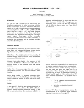
  • 1. A Review of the Revisions to API 14.3 / AGA 3 – Part 2 Tom Cathey Wedge Measurement & Control, Inc. 1415 Louisiana Suite 1500, Houston Texas 77056 Introduction In April of 2000, revisions to the specification and installation requirements for orifice meters was published by the American Gas Association in the form of the AGA Report No. 3 – Part 2, Fourth Edition. This purblication is also correctly known as API 14.3, Part 2, ANSI/API 14.3, Part 2-2000 and GPA 8185, Part 2. This report applies to fluids that are considered to be clean, single-phase, homogenous and Newtonian measured using concentric, square edged, flange-tapped orifice meters.The requirements for the construction of orifice meter tubes, as defined in this publication, will be discussed in greater detail throughout this paper. Definition of Terms Primary Element – Defined as the orifice plate, the orifice plate holder with associated differential pressure sensing taps, the meter tube, and flow conditioner if used. Meter Tube – The straight sections of pipe, including all segments integral to the orifice plate holder upstream and downstream of the orifice plate. Diameter Ratio (Beta Ratio) – For purposes of this discussion, the definition is the measured orifice plate bore diameter divided by the measured meter tube internal diameter. Orifice Plate – A thin square-edged plate with a machined circular bore concentric with the meter tube I.D. when installed. Orifice Plate Holder – A pressure containing piping element, such as a set of orifice flanges or an orifice fitting used to contain and position the orifice plate in the piping system. Design A beta ratio of.75 should be used as the design criteria for new orifice meter installations. The 2000 publication provides required minimum installation lengths UL and DL for meter tubes with no flow conditioners in Table 2-7. Minimum installation lengths for meter tubes with the 1998 Concentric 19-Tube Flow Straighteners are provided in Tables 2-8a and 2-8b. You may be familiar with the following drawing taken from Figure 2-6 of the publication. In many instances it may be difficult or impossible for the engineer to control upstream piping configurations. This is been a common problem for many companies over the years and some have taken this in to consideration when designing their measurement packages. In all but two of the applications identified in Table 2-7, a UL length of 44D at a beta ratio of .75 meets minimum requirements. The exceptions are as follows: o Two 90° elbows in perpendicular planes where S<5Di o Any other configuration (catch all category) For two 90° elbows in perpendicular planes, the recommendation is 95 published inside diameters beginning at beta ratios of .50 through .75.
  • 2. For configurations not specifically addressed in Table 2-7, 145 published inside diameters are recommended for beta ratios of .40 through .75. Some have incorporated a piping segment upstream of the meter tube so that the “S” dimension can be controlled. For tubes with The Uniform Concentric 1998 19-Tube Bundle, there are multiple configurations that are not allowed at the higher beta ratios. This means that it is not possible to find an acceptable location for the Concentric 19-Tube Bundle under these specific conditions. A few examples follow: • Single 90° tee used as an elbow but not as a header element for beta ratios of .67 and higher. • Partially closed valves (at least 50% open) for beta ratios of .60 and higher. Required minimum lengths for other types of flow conditioners are not specified although flow testing in situ and at flow-testing laboratories is addressed. Many companies have now changed their engineering standards to accommodate other types of one and two piece flow conditioners such as those produced by Gallagher, Canadian Pipeline Accessories and Daniel. Flow Conditioners Flow conditioners are divided into two categories: flow straighteners and isolating flow conditioners. Flow straighteners are defined as “Devices that remove or have limited ability to accurately replicate the orifice plate coefficient of discharge database values”. Isolating flow conditioners are defined as “Devices that effectively remove the swirl component from the flowing stream while redistributing the stream to produce flow conditions that accurately replicate the orifice plate coefficient of discharge database values”. The 1998 Uniform Concentric 19-Tube bundle is considered a flow straightener and the physical specifications are considerably different from the requirements listed in the 1991 publication for straightening vanes. The individual tubes must be of uniform smoothness, outer diameter and wall thickness. Commercially available seamless carbon steel tubing is readily available and most commonly used. The individual wall thickness of the tubes shall be less than or equal to 2.5% of the published internal diameter. For example: The individual wall tube thickness for a 3” schedule 40 meter tube (3.068”) must be .025 X 3.068 or 0.0767” or less. The individual tubes must be chamfered on both ends not less than 50% of the wall thickness by 45 degrees. The tubes must be arranged in a cylindrical pattern and the individual tube outer walls must come in direct contact with each other. The outside diameter of the tube bundle must be a minimum of 95% of the published internal diameter of the meter tube and can obviously be no greater than the published internal diameter. In order to ensure that the bundle outer tube walls come in direct contact with each other and achieve an outside diameter greater than or equal to 95% of the published inside diameter of the meter tube, the correct O.D. tubing must be used as illustrated in the table below for schedule 40 piping. Meter Vane Minimum Vane Tube ID " Tube O.D. " Bundle O.D. " 3.068 19/32 2.9146 4.026 13/16 3.8247 6.065 1- 3/16 5.7618 7.981 1- 5/8 7.5820 10.020 2 9.5190 The required length of the tube bundles must be as follows: • 3 X NPS for 2” • 2.5 X NPS for 3” & 4” • 2 X NPS for 6” and above Flow conditioners not meeting the requirements of the 1998 Uniform Concentric Tube Bundle are considered as Other Flow Conditioners. While the 2000 publication does not recommend any particular type of flow conditioner, specific criterion for evaluation of installation and/or flow conditioner testing is provided. These tests define the meter tube lengths and flow conditioner locations for acceptable performance. Significant research and numerous flow studies have been conducted since 1991 to test various flow conditioner designs with repeatable and acceptable results.
  • 3. Meter Tube Surface Roughness In the 2000 publication, sections 2.5.1.1 through 2.5.1.1.3 address the inside surface of meter tubes as follows: For meter runs with nominal diameters of 12 inches or smaller: • 300 micro inches for diameter ratios equal to or less than 0.6 • 250 micro inches for diameter ratios greater than or equal to .60 • The minimum roughness shall not be less than 34 micro inches for all diameter ratios • For meter runs with nominal diameters larger than 12 inches: • 600 micro inches for diameter ratios equal to or less than 0.6 • 500 micro inches for diameter ratios greater than or equal to 0.6 • The minimum roughness shall no be less than 34 micro inches for all diameter ratios. Readily available cold drawn seamless pipe used in the construction of meter tubes generally falls within 75 to 150 microinches. When other types of commercial pipe are used, honing to achieve the desired finish is required. Digital profilometers are commonly used to accurately determine this measurement Meter Tube Internal Diameter and Roundness Tolerance This is specified in sections 2.5.1.2 through 2.5.1.4.5 and includes general restrictions related to offsets, shoulders and welding seams. Also included are recesses and protrusions. Generally, single and dual chamber flangeneck fittings are used in the United States in the construction of orifice meter tubes. There are exceptions such as weldnek fittings and orifice flange unions but in custody transfer applications, this is rare. When care is taken in the selection of orifice fittings, pipe, and weld fittings and with proper alignment, welding and grinding techniques are applied, the requirements are not difficult to meet. The equations used to determine roundness and diameter tolerances are illustrated in the following: Examples of the allowable tolerances for various diameters are illustrated in the following table: A = (Any US diameter within one Dm ) - Dm ≤ 0.25% Dm B = Maximum US Diameter – Minimum US Diameter ≤ 0.50% Dm C = Any downstream diameter - Dm ≤ 0.50% Dm Note: Dm is equal to the average of the H,V,LV and RV measurements taken 1" from the upstream face of the orifice plate. Nominal Mean ID Upstream Downstream Pipe Size ( Dm) A B C 2 1.939 0.005 0.010 0.010 2.067 0.005 0.010 0.010 3 2.900 0.007 0.015 0.015 3.068 0.008 0.015 0.015 4 3.826 0.010 0.019 0.019 4.026 0.010 0.020 0.020 6 5.761 0.014 0.029 0.029 6.065 0.015 0.030 0.030
  • 4. Portrusions resulting from gaskets or sealing devices in to the pipe bore are not permitted. Companion flanges are used in conjunction with weldnek orifice fittings and the correct gaskets to minimize the potential for this type of problem. Utilization of incorrect piping schedule seal rings can cause either a restriction or a recess in excess of 0.25 inches as specified in sections 2.5.1.4.2 and 2.5.1.4.3. Pressure Taps Meter tubes using flange taps shall have the the center of the upstream tap hole placed one inch from the upstream face of the orifice plate. The center of the downstream pressure tap shall be one inch from the downstream face of the orifice plate. There are allowable deviations specified in Figure 2-3 of the April 2000 publication and her again the recommendation is to use a Beta Ration of .75 to determine the allowable tolerance. The information below illustrates this: Nominal Pipe Figure 2-3 Minimum Maximum Size Distance Distance 2" & 3" 1" +/- 0.015" 0.985" 1.015" ≥4" 1" +/- 0.035" 0.965" 1.035" The tap holes shall be radially drilled radially to the meter tube. The centerline of the tap hole shall intersect and form a right angle with the axis of the meter tube. All pressure tap holes must be round to to a tolerance of ± 0.004 inch throughout their length. The diameter and diameter tolerances are contained in the following table: Nominal Pipe Tap Hole Minimum Maximum Size Diameter Diameter Diameter 2" & 3" 0.375" +/- 0.016" 0.359" 0.391" 4" or Larger 0.500" +/- 0.016" 0.484" 0.516" Eccenricity The orifice plate bore must be concentric with both the upstream and the downstream inside bore of the orifice plate holder. The orifice fitting manufacturers accomplish this task for the smaller bore sizes by utilizing a metal to metal centering technique. Of course the smaller the bore size, the more difficult it is to meet the criteria set forth in Section 2.6. The eccentricity tolerances for various bore sizes are illustrated in the following table: X-X'/2 = Parallel to the Differential Pressure Taps (Y-Y'/2)*4 Axis = Perpendicular to the Differential Pressure Taps Note: All Tolerances Listed are at 0.75 Beta Ratio Value in Inches Nominal Bore X Axis Y Axis Pipe Size Tolerance Tolerance 2 1.939 0.006 0.024 2.067 0.006 0.024 3 2.900 0.009 0.036 3.068 0.009 0.036 4 3.826 0.012 0.048 4.026 0.012 0.048 6 5.761 0.017 0.068 6.065 0.018 0.072 8 7.625 0.023 0.092 7.981 0.024 0.096 10 9.750 0.029 0.116 10.020 0.03 0.120 12 11.374 0.034 0.136 11.626 0.035 0.140 11.938 0.036 0.144 16 14.312 0.043 0.172 14.688 0.044 0.176 15.000 0.045 0.180 Thermometer Well Location Thermometer wells should be located to sense the average temperature of the fluid at the orifice plate. The wells may be placed on the downstream side of the orifice plate not closer than DL or farther than 4DL as illustrated in tables 2-7 and 2-7 of AGA 3, Report #3. If a flow conditioner is used, the thermometer well may be located no closer than 36 inches upstream of the flow conditioner inlet.