Dell 3-2-1 Reference Configurations: High available and scalable performance with Dell PowerEdge R720-based solutions

Dell 3-2-1 Reference Configurations consisting of Dell PowerEdge R720 servers, Dell Force10 S4810P switches, and Dell EqualLogic PS6110XV storage provide a range of configuration options so that you can select the one that is right for your business needs. Additionally, each configuration is easily scalable to accommodate for business growth. The 3-2-1 base configuration provides a robust solution for any business needing to support up to 500 users on multiple business applications. Our tests demonstrate this solution supporting 500 users per VM for four VMs including two database VMs, one email VM, and one collaboration application VM. If the number of users you need to support exceeds the user count the base configuration provides, adding another Dell PowerEdge R720 server to make a 4-2-1 configuration can support up to 1,000 users on multiple business applications while maintaining high availability. Our tests demonstrate this solution supporting 1,000 users per VM in the same four VMs as the 3-2-1 solution. Additionally, these configurations are so easy to scale upward that you can complete the process of adding a server in a matter of two hours or less from start to finish. If you require support for an even higher number of users, adding a server and storage array to the base configuration, to make a 4-2-2 configuration allows for up to 1,500 users on multiple business applications. Our tests demonstrated this when we ran 1,500 users against each of the four VMs. Better yet, adding a Dell EqualLogic PS6110XV storage array to an existing 4-2-1 configuration is a cinch, taking under 30 minutes start to finish. All of these Dell Reference Configurations give your business the reliability of highly available hardware configurations, greatly reducing downtime resulting from any hardware malfunctions. By choosing proven Dell architecture, you avoid the hassles of putting your infrastructure together piece by piece, reducing the potential for error and providing you with a sturdy solution that is easily scalable to fit your present and future needs.

Recomendados
Recomendados
Más contenido relacionado
La actualidad más candente
La actualidad más candente (20)
Similar a Dell 3-2-1 Reference Configurations: High available and scalable performance with Dell PowerEdge R720-based solutions
Similar a Dell 3-2-1 Reference Configurations: High available and scalable performance with Dell PowerEdge R720-based solutions (20)
Más de Principled Technologies
Más de Principled Technologies (20)
Dell 3-2-1 Reference Configurations: High available and scalable performance with Dell PowerEdge R720-based solutions
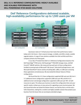
- 1. DELL 3-2-1 REFERENCE CONFIGURATIONS: HIGHLY AVAILABLE AND SCALABLE PERFORMANCE WITH DELL POWEREDGE R720-BASED SOLUTIONS Businesses need an IT infrastructure that meets their performance needs— today and in the future—that is easy to manage, is reliable, and offers simple, scalable upgrade options. A range of new solutions available from Dell and Microsoft lets a company achieve all of these goals. In our labs, PT tested three Dell 3-2-1 Reference Configurations based on the Dell PowerEdge™ R720 server, Dell EqualLogic™ PS6110XV storage arrays, and Dell Force10™ S4810P switches. We measured how well each of these configurations handled increasing levels of Microsoft® SQL Server®, Microsoft Exchange Server, and Microsoft SharePoint® Server activity simulating 500, 1,000, or 1,500 users accessing these applications simultaneously. We also tested the failover feature of these configurations. We found that the 3-2-1 base configuration supported 500 users per VM, the 4- 2-1 additional server configuration supported 1,000 users per VM, and the 4-2-2 additional server and storage configuration supported 1,500 users per VM—all with resources to spare. This allows your business to select the configuration that suits your specific needs or allows you an easy avenue for upgrading as your business grows. We also found that when we tested the failover feature, we had less than a minute and a half of downtime, making this a resilient and highly available solution that protects your business from the losses that can accompany extended outages. AUGUST 2012 A PRINCIPLED TECHNOLOGIES TEST REPORT Commissioned by Dell Inc.
- 2. PERFORMANCE THAT SCALES We tested three Dell 3-2-1 Reference Configurations by simulating a specific user count workload on four VMs: Two database application VMs, one email application VM, and one collaboration application VM. Each configuration builds on the one that precedes it to be able to handle a higher number of users. 3-2-1 base configuration. This configuration has two Dell PowerEdge R720 application servers, one Dell PowerEdge R620 management server, two 10G Force10 S4810P switches, and one Dell EqualLogic PS6110XV storage array. In our testing, this configuration supported a target of 500 users per VM. 4-2-1 additional server configuration. This configuration takes the base configuration and adds a third Dell PowerEdge R720 server to boost performance. In our testing, this configuration supported a target of 1,000 users per VM. 4-2-2 additional server and storage configuration. This configuration takes the extra server configuration described above and adds a second Dell EqualLogic PS6110XV array to achieve the greatest performance of all. In our testing, this configuration supported a target of 1,500 users per VM. Figure 1 shows a summary of the users that each configuration supported on each of the VMs. Figure 1. Dell Reference Configurations supported anywhere from 500 users to 1,500 users per VM. Dell 3-2-1 Reference Configurations: Highly available and scalable A Principled Technologies test report 2 performance with Dell PowerEdge R720-based solutions
- 3. We ran Microsoft SQL Server 2012 for the two database application VMs, Microsoft Exchange Server 2010 SP2 for the email application VM, and Microsoft SharePoint Server 2010 SP1 for the collaboration application VM. Setting up high-availability architecture can be difficult, but the 3-2-1 Reference Configurations based on Dell PowerEdge R720 servers with Intel® Xeon® processors make it easy. Additionally, Microsoft System Center 2012 Operations Manager (SCOM 2012) and System Center 2012 Virtual Machine Manager (SCVMM 2012) build on Windows Server 2012 Hyper-V and Failover Cluster Manager, and enhance your ability to manage the entire solution—including your Dell PowerEdge servers, the failover cluster, and your virtual machines—from a single location. With these management tools, IT administrators can monitor health status, hardware, and performance information for the entire configuration. To learn more about the setup process and the function the management tools provide, see our companion configuration guide.1 As easy as 3-2-1 Dell 3-2-1 Reference Configurations follow the 3-2-1 model, where the configuration comprises three servers, two switches, and one storage array. As shown by the two upgraded configurations, the 3-2-1 model can be scaled up to meet higher computing and storage demands. For each configuration, we created a failover cluster with four Hyper-V™ VMs on the Dell PowerEdge R720 servers and Dell EqualLogic PS6110XV storage, and used them to run the three common businesses applications. Creating a failover cluster between the Hyper-V hosts allows a VM to quickly move from one host server to another when used in conjunction with shared storage. This minimizes downtime in that a VM can quickly move from one host server to another if that host server malfunctions or goes offline. Additionally, it allows for an IT administrator to make planned moves from one server host to another without having to take the VM offline. We put the configurations to the test by simulating 500, 1,000, and 1,500 users simultaneously accessing each of the two database VMs, using email, and using SharePoint. Our finding? Not only could the servers run these heavy workloads, they did so with plenty of resources to spare for future growth. In addition to measuring the performance the Dell PowerEdge R720 servers provide, we also abruptly removed power from one of the host servers to simulate what would happen in the unlikely event of a complete server failure. After we did so, the database and SharePoint VMs that were hosted on this server failed over seamlessly and began running on the other Dell PowerEdge R720 with very little downtime; about a 1 http://www.principledtechnologies.com/clients/reports/Dell/R720_321_upgrade_configuration.pdf Dell 3-2-1 Reference Configurations: Highly available and scalable A Principled Technologies test report 3 performance with Dell PowerEdge R720-based solutions
- 4. minute and a half. Such seamless failover means your data is available when you need it – even in the case of a server catastrophe. Two clustering options for high availability There are two options for high availability clusters: creating a cluster either at the application level or at the host level. Clustering at the host level by using Hyper-V failover clusters, which we did, works with any application, whether it supports clustering or not, and enables more streamlined configuration, management, and future growth of the cluster environment while maintaining a very low downtime in the event of a failover. If the absolute smallest possible downtime is your primary goal, then clustering at the application level may be a better option. In this configuration, you set up each individual application for clustering on each server/VM. Some applications (for instance SQL Server) support this sort of clustering. For more information, see our companion configuration guide. WHAT WE FOUND We set up four VMs across our two Dell PowerEdge R720 host servers to house the applications. In the case of the 4-2-2 and 4-2-1 configurations, the mail application VM ran on its own host server, one of the database applications VM ran on a second host server, and the other database and the collaboration application VMs ran on a third server. In the case of the 3-2-1 configuration, the mail and collaboration application VMs ran on different host servers, each of which also ran one of the two database application VMs. Our goal was to run workloads simulating 500 users in the 3- 2-1 configuration, 1,000 users in the 4-2-1 configuration, and 1,500 users in the 4-2-2 configuration in each VM to verify each configuration could handle the desired user load. Because we wanted to maintain high availability, we needed to ensure that each server could handle the load without oversubscribing resources so that they could fail over if necessary. Additionally, we ran the workload on the base 3-2-1 configuration while simulating a failover event to demonstrate that a single host server would be able to maintain the same level of performance running all four VMs. Figure 2 shows the SQL Server performance for the three configurations. Each of the two SQL Server VMs achieved the orders per minute (OPM) to demonstrate supporting the respective user count. Assuming that each user is generating approximately six OPM, 500 users would mean 3,000 OPM for the 3-2-1 configuration, 1,000 users would mean 6,000 OPM for the 4-2-1 configuration, and 1,500 users would mean 9,000 OPM for the 4-2-2 configuration. As Figure 2 shows, in each configuration, both VMs easily achieved the required OPM to support the set user count for each configuration, obtaining 3,241 and 3,232 OPM for the 3-2-1 configuration, 6,878 and Dell 3-2-1 Reference Configurations: Highly available and scalable A Principled Technologies test report 4 performance with Dell PowerEdge R720-based solutions
- 5. 6,759 OPM for the 4-2-1 configuration, and 9,480 and 9,439 OPM for the 4-2-2 configuration. SQL Server performance (VM 1 and VM 2) 10,000 Orders per minute 8,000 6,000 4,000 VM 1 2,000 VM 2 0 3-2-1 4-2-1 4-2-2 configuration configuration configuration (500 users) (1,000 users) (1,500 users) Figure 2. SQL Server performance for the three configurations. Higher numbers are better. Figure 3 shows the Exchange Information Store read and write latency during the LoadGen workload for the three configurations. In all cases, the Exchange Server VM delivered latencies well within the acceptable parameters—a read latency less than 20 milliseconds and a write latency less than the read latency. Exchange latency (VM 3) 14 12 10 Read Milliseconds 8 latency 6 4 Write 2 latency 0 3-2-1 4-2-1 4-2-2 configuration configuration configuration (500 users) (1,000 users) (1,500 users) Figure 3. Exchange latency during the LoadGen workload for the three configurations. Lower numbers are better. Figure 4 shows the SharePoint Server performance for the three configurations. We assumed that each user would generate approximately one task per minute and determined acceptable performance to be within 95 percent of the theoretical maximum. This means that 500 users would need to generate 475 tasks per minute for Dell 3-2-1 Reference Configurations: Highly available and scalable A Principled Technologies test report 5 performance with Dell PowerEdge R720-based solutions
- 6. the 3-2-1 configuration, 1,000 users would need to generate 950 tasks per minute for the 4-2-1 configuration, and 1,500 users would need to generate 1,425 tasks per minute for the 4-2-2 configuration. The SharePoint VM performed above the required tasks per minute for each configuration. Additionally, the average latency in each case was well below the 1-second threshold, at 0.24 seconds, 0.17 seconds, and 0.21 seconds for the 3-2-1, 4-2-1, and 4-2-2 configurations, respectively. SharePoint Server performance (VM 4) 1,600 1,400 Tasks per minute 1,200 1,000 800 600 400 200 0 3-2-1 4-2-1 4-2-2 configuration configuration configuration (500 users) (1,000 users) (1,500 users) Figure 4. SharePoint performance in tasks per minute during the WSSDW workload for the three configurations. Higher numbers are better. Figure 5 shows the results for average CPU utilization and RAM utilization on each of the Dell PowerEdge R720 host servers. Lower numbers are better. As our results show, the servers were able to handle the load while maintaining resource usage standards for high availability, and even had room for future growth. Hyper-V Host 1 Hyper-V Host 2 Hyper-V Host 3 (hosting SQL 1 + (hosting SQL 2 VM) (hosting Exchange VM) Configuration SharePoint VMs) % CPU % RAM % CPU % RAM % CPU % RAM utilization utilization utilization utilization utilization utilization 3-2-1 configuration (500 7.21 21.82 10.05 24.97 users) 4-2-1 configuration (1,000 11.61 21.89 6.91 14.67 4.53 19.65 users) 4-2-2 configuration (1,500 15.07 21.48 8.93 14.38 17.12 19.48 users) Figure 5. CPU and RAM utilization for the Dell PowerEdge R720 host servers. Lower numbers are better. Dell 3-2-1 Reference Configurations: Highly available and scalable A Principled Technologies test report 6 performance with Dell PowerEdge R720-based solutions
- 7. Figure 6 shows the average I/O and latency data for the storage within each configuration. In the 3-2-1 and 4-2-1 configurations, this is a single Dell EqualLogic PS6110XV array and in the 4-2-2 configuration, this is two Dell EqualLogic PS6110XV arrays. 3-2-1 4-2-1 4-2-2 configuration configuration configuration (500 users) (1,000 users) (1,500 users) Average reads IOPS 938.3 1,929.0 2,716.7 Average writes IOPS 748.4 1,512.8 1,863.6 Average total IOPS 1,686.7 3,441.8 4,580.3 Average read latency (ms) 6.2 8.3 6.4 Average write latency (ms) 1.2 1.4 1.2 Figure 6. Average I/O and latency data for the Dell EqualLogic PS6110XV arrays. We determined acceptable storage performance as having a read latency under 20 milliseconds. As our results show, the latency is well below this level in all three configurations while under test. For more information on how we set up the tests to verify the performance capabilities of our high-availability hardware setup, see the What we tested section. When a failover event occurs and a server goes offline, the failover cluster immediately detects the change and reboots any VMs that were running on that server over to an active server in the cluster. Because the shared storage between the servers holds the data for the VMs, this is generally a very quick process with minimal downtime. To simulate a failover event, we used the 3-2-1 configuration and removed power from one of the Hyper-V hosts, specifically, the server that was hosting the SQL Server 2012 VM and the SharePoint VM while we were running the test workload. The failover cluster quickly detected the failure of the host server and automatically migrated the VMs to the other host server. We were able to re-establish connection and continue the workload tests with only a slight interruption (1 minute 27 seconds). Furthermore, we measured the resource utilization on the single host server running all three VMs under workload stress and found that the average resource utilization was at 14.51 percent CPU and 38.26 percent RAM, with no observable change in performance. WHAT WE TESTED We created a failover cluster using Dell PowerEdge R720 servers with cluster- shared volumes on the Dell EqualLogic PS6110XV storage array or arrays, using Dell Force10 S4810P switches. We then used Hyper-V to create four virtualized servers in the failover cluster to run the line-of-business applications: a collaboration server running Microsoft SharePoint Server, a mail server running Microsoft Exchange Server, and two database servers running Microsoft SQL Server. To demonstrate that each VM could handle the required users, we ran benchmarks against each VM simulating 500, 1,000, Dell 3-2-1 Reference Configurations: Highly available and scalable A Principled Technologies test report 7 performance with Dell PowerEdge R720-based solutions
- 8. or 1,500 users accessing data on each. We staggered the benchmarks, allowing LoadGen to start first and warm up for 15 minutes, then starting WSSDW and allowing it to warm up for 5 minutes, then starting DVD Store and allowing for an additional 10 minutes of run time before taking performance measurements. We measured the performance of the four virtual machines over a 30-minute period of our test runs, and report the median of three runs for each configuration. We based the median run on the median storage latency for each configuration For step-by-step instructions on how we tested, see Appendix B. Database testing We used the DVD Store Version 2 (DS2) benchmark to simulate 500, 1,000, or 1,500 database users. DS2 is an open-source application that models an online DVD Store where customers log in, browse movies, and purchase movies. DS2 reports its results in orders per minute that the server can handle. We ran DS2 with a 100GB database and think times of 0.5, 0.18, and 0.12 seconds for the 3-2-1, 4-2-1, and 4-2-2 configurations respectively, so that each of our 32 threads represented 500, 1,000, or 1,500 users completing one order approximately every 10 seconds against each of the two SQL Server 2012 VMs. The benchmark then uses a default value of three searches on average before each order. We define a minimum acceptable score as 3,000 OPM for the 3-2-1 configuration, 6,000 OPM for the 4-2-1 configuration, and 9,000 OPM for the 4-2-2 configuration. We allowed for a 10- minute warm-up period, and then set the measurement period to 30 minutes. For more details about the DS2 tool, see http://www.delltechcenter.com/page/DVD+Store. Mail testing To test the configuration’s mail server performance, we used the Microsoft Load Generator 2010 (LoadGen) benchmark, which performs tasks to simulate a standard user generating mail activity. We simulated 500, 1,000, and 1,500 users for the 3-2-1, 4- 2-1, and 4-2-2 configurations and used the following settings: Mailbox Profile: 250MB mailboxes Action Profile: Outlook_500 Client Type: Outlook 2007 Cached LoadGen simulates the mail activity for the designated user count. We set the benchmark to run for 1 hour and 15 minutes: 15 minutes for LoadGen to warm-up, then 15 minutes for the remaining benchmarks to start and warm up, 30 minutes of measured performance time, and 15 minutes as a cool-down period to complete the run. Dell 3-2-1 Reference Configurations: Highly available and scalable A Principled Technologies test report 8 performance with Dell PowerEdge R720-based solutions
- 9. For more details about LoadGen, see http://www.microsoft.com/downloads/details.aspx?FamilyId=DDEC1642-F6E3-4D66- A82F-8D3062C6FA98&displaylang=en. Collaboration testing To simulate the traffic of 500, 1,000, and 1,500 SharePoint Server 2010 users, we used a customized version of the WSSDW 1.0.0.0 Beta test. This test creates sample data, populates the server with it, and simulates SharePoint Server users completing everyday tasks. We used Visual Studio 2010 to execute the test workload, generating a realistic user workload where each of the simulated users performed a task approximately every minute. To do this, we set up the test to run 67, 134, or 200 users with an 8-second think time between each of the various tasks to simulate 500, 1,000, or 1,500 users, respectively. (Note that 67 and 134 will technically yield 502.5 and 1005 simulated users, but in the case of our calculations, this difference is negligible.) We determine acceptable performance if the latency in each case is under 1 second and the average number of tasks per minute is within 95 percent of the theoretical maximum. For more details about SharePoint Server, see http://office.microsoft.com/en- us/sharepoint-server-help/. WHAT THIS MEANS FOR YOU Dell 3-2-1 Reference Configurations consisting of Dell PowerEdge R720 servers, Dell Force10 S4810P switches, and Dell EqualLogic PS6110XV storage provide a range of configuration options so that you can select the one that is right for your business needs. Additionally, each configuration is easily scalable to accommodate for business growth. The 3-2-1 base configuration provides a robust solution for any business needing to support up to 500 users on multiple business applications. Our tests demonstrate this solution supporting 500 users per VM for four VMs including two database VMs, one email VM, and one collaboration application VM. If the number of users you need to support exceeds the user count the base configuration provides, adding another Dell PowerEdge R720 server to make a 4-2-1 configuration can support up to 1,000 users on multiple business applications while maintaining high availability. Our tests demonstrate this solution supporting 1,000 users per VM in the same four VMs as the 3-2-1 solution. Additionally, these configurations are so easy to scale upward that you can complete the process of adding a server in a matter of two hours or less from start to finish. If you require support for an even higher number of users, adding a server and storage array to the base configuration, to make a 4-2-2 configuration allows for up to Dell 3-2-1 Reference Configurations: Highly available and scalable A Principled Technologies test report 9 performance with Dell PowerEdge R720-based solutions
- 10. 1,500 users on multiple business applications. Our tests demonstrated this when we ran 1,500 users against each of the four VMs. Better yet, adding a Dell EqualLogic PS6110XV storage array to an existing 4-2-1 configuration is a cinch, taking under 30 minutes start to finish. All of these Dell Reference Configurations give your business the reliability of highly available hardware configurations, greatly reducing downtime resulting from any hardware malfunctions. By choosing proven Dell architecture, you avoid the hassles of putting your infrastructure together piece by piece, reducing the potential for error and providing you with a sturdy solution that is easily scalable to fit your present and future needs. Dell 3-2-1 Reference Configurations: Highly available and scalable A Principled Technologies test report 10 performance with Dell PowerEdge R720-based solutions
- 11. APPENDIX A – SERVER AND STORAGE CONFIGURATION INFORMATION Figure 7 provides detailed configuration information for the servers in our configuration, and Figure 8 provides configuration information for the Dell EqualLogic PS6110XV storage array. Dell PowerEdge R620 (management System Dell PowerEdge R720 (host servers) server) Power supplies Total number 2 2 Vendor and model number Dell D750E-S1 Dell E750E-S0 Wattage of each (W) 750 750 Cooling fans Total number 6 7 Vendor and model number AVC DBTC0638B2U Delta GFC0412DS Dimensions (h x w) of each 2.5” x 2.5” 1.5” x 1.75” Volts 12 12 Amps 1.20 1.82 General Number of processor packages 2 2 Number of cores per processor 8 8 Number of hardware threads per core 2 2 System power management policy Balanced Balanced CPU Vendor Intel Intel Name Xeon Xeon Model number E5-2680 E5-2660 Stepping C1 C1 Socket type FCLGA2011 FCLGA2011 Core frequency (GHz) 2.70 2.20 Bus frequency 8 GT/s 8 GT/s L1 cache 32 KB + 32 KB (per core) 32 KB + 32 KB (per core) L2 cache 256 KB (per core) 256 KB (per core) L3 cache 20 MB (shared) 20 MB (shared) Platform Vendor and model number Dell PowerEdge R720 Dell PowerEdge R620 Motherboard model number OM1GCR 07NDJ2X03 BIOS name and version Dell 1.1.2 Dell 0.3.37 BIOS settings Default Default Memory module(s) Total RAM in system (GB) 64 32 Vendor and model number Hynix HMT31GR7BFR4A-H9 Hynix HMT351R7BFR8C-PB Type PC3L-10600R PC3-12800R Speed (MHz) 1,333 1,600 Speed running in the system (MHz) 1,333 1,600 Timing/Latency (tCL-tRCD-tRP- 9-9-9-36 10-10-10-37 tRASmin) Dell 3-2-1 Reference Configurations: Highly available and scalable A Principled Technologies test report 11 performance with Dell PowerEdge R720-based solutions
- 12. Dell PowerEdge R620 (management System Dell PowerEdge R720 (host servers) server) Size (GB) 8 4 Number of RAM module(s) 8 8 Chip organization Double-sided Double-sided Rank Dual Dual Operating system Windows Server 2012 Release Windows Server 2012 Release Name Candidate Datacenter Edition Candidate Datacenter Edition Build number 8400 8400 File system NTFS NTFS Kernel ACPI x64-based PC ACPI x64-based PC Language English English Graphics Vendor and model number Matrox® G200eR Matrox G200eR2 Driver Microsoft 6.2.8400.0 (6/21/2006) Microsoft 6.2.8400.0 (6/21/2006) RAID controller Vendor and model number Dell PERC H710P Mini PERC S110 Firmware version 21.0.2-0001 3.0.0-137 Driver version LSI Corporation 5.2.122.0 (4/3/2012) Dell Inc. 3.0.0.134 (10/14/2011) Cache size (MB) 1024 1 GB Hard drives Vendor and model number Dell WD3000BKHG-18A29V0 Dell MZ-5S71000-0D3 Number of drives 2 2 Size (GB) 300 100 RPM 10,000 N/A Type SAS SATA SSD Network adapters First network adapter Vendor and model number Intel Ethernet 10G 4P X540/I350 rNDC Intel I350 Gigabit Controller Type Integrated Integrated Driver Intel 3.1.53.0 (6/11/2012) Microsoft 12.0.150.0 (2/29/2012) Second network adapter Vendor and model number Intel Ethernet Server Adapter X520-2 Type PCIe Driver Intel 3.1.61.0 (7/5/2012) Optical drive(s) Vendor and model number TEAC DV-28SW TSSTcorp TS-U633J Type DVD-ROM DVD-ROM USB ports Number 4 external, 1 internal 4 external, 1 internal Type 2.0 2.0 Figure 7. System configuration information for the test servers. Dell 3-2-1 Reference Configurations: Highly available and scalable A Principled Technologies test report 12 performance with Dell PowerEdge R720-based solutions
- 13. Storage array Dell EqualLogic iSCSI SAN Array Dell EqualLogic PS6110XV Number of active storage controllers 1 Number of active storage ports 1 Firmware revision V5.0.4 Disk vendor and model number Dell ST9300653SS Disk size (GB) 300 Disk buffer size (MB) 64 Disk RPM 15,000 Disk type SAS Switch number/type/model/ firmware revision 2 x Dell Force10 S4810P v8.3.10.3 Figure 8. Detailed configuration information for the storage array and switch. Dell 3-2-1 Reference Configurations: Highly available and scalable A Principled Technologies test report 13 performance with Dell PowerEdge R720-based solutions
- 14. APPENDIX B – HOW WE TESTED Test client configuration For the test clients, we configured VMs on a server, each running Windows Server 2008 R2 SP1 with the latest available updates. We configured 10 VMs to distribute the LoadGen workload, two VMs for the DVD Store workload (one per SQL Server instance), and one VM to run the WSSDW test workload. Configuring the infrastructure server We configured our infrastructure server, which would serve as our domain controller, as follows. Installing Microsoft Windows Server 2012 Release Candidate Datacenter 1. Insert the installation media into the CD/DVD drive. 2. When the Windows Setup window appears, click Next, and then Install Now. 3. Select Windows Server 2012 Release Candidate Datacenter (Server with a GUI), and click Next. 4. Check I accept the license terms, and click Next. 5. Click Custom: Install Windows only (advanced). 6. Select Drive 0 Unallocated Space, and click Next, at which point Windows will begin installing, and will restart automatically after completing. 7. When the Settings page appears, fill in the Password and Reenter Password fields with the same password. 8. Log in with the previously set up password. Configuring Windows Update 1. In the left pane of the Server Manager window, click Local Server. 2. In the main frame, next to Windows Update, click Never configured. 3. In the Windows Update window, in the main pane, click Let me choose my settings. 4. Under Important updates, select Never check for updates (not recommended), and then click OK. 5. In the left pane, click Check for updates, and install all available updates. 6. Close the Windows Update window. Configuring Windows Firewall 1. In Server Manager, click ToolsWindows Firewall with Advanced Security. 2. In the Overview section, click Windows Firewall Properties. 3. In the Domain Profile tab, for Firewall state, click Off. 4. In the Private Profile tab, for Firewall state, click Off. 5. In the Public Profile tab, for Firewall state, click Off. 6. Then click OK. 7. Close the Windows Firewall Properties window. Setting up Remote Desktop 1. In the Local Server tab of the Server Manager window, next to Remote Desktop, click Disabled. 2. In the System Properties window that appears, in the Remote Desktop section, select the Allow remote connections to this computer radio button, and click OK when the warning message appears. Dell 3-2-1 Reference Configurations: Highly available and scalable A Principled Technologies test report 14 performance with Dell PowerEdge R720-based solutions
- 15. 3. Uncheck Allow connections only from computers running Remote Desktop with Network Level Authentication (recommended), and click OK. Setting up IE Enhanced Security Configuration 1. In the Local Server tab of the Server Manager window, next to IE Enhanced Security Configuration, click On. 2. In the Internet Explorer Enhanced Security Configuration window, select the Off radio buttons for both Administrators and Users, and click OK. Installing the Active Directory Domain Services role 1. Launch Server Manager and select Add roles and features. 2. Click Next at the Add Roles and Features Wizard. 3. Select Role-based or feature-based installation, and click Next. 4. Select the AD server from the server pool, and click Next. 5. Select Active Directory Domain Services from the list of Roles, click the Add Services button to add features that are required by Active Directory Domain Services, and click Next. 6. Accept the defaults selected by setup at the Features screen, and click Next. 7. Click Next at the AD DS screen. 8. Select Restart the destination server automatically if required at the confirmation screen, and click Install. 9. Click Promote this server to a domain controller. 10. Select Add a new forest, type in the Root domain name (fqdn), and click Next. 11. Type in and confirm the password, and click Next. 12. Click Next at the DNS Options screen. 13. Verify the NetBIOS name, and click Next. 14. Accept the default paths, and click Next. 15. Review the options, and click Next. 16. Verify the prerequisite check passes successfully, and click Install. Configuring the network For our high-availability setup, we configured the network cabling of the hardware as shown in Figure 3. Note that we did not connect the stacking connections until we completed the switch configuration in the next section. We used a Dell PowerConnect 5224switch for our infrastructure network, which we used to connect the 3-2-1 configurations to the infrastructure server (domain controller) and client machines. Dell 3-2-1 Reference Configurations: Highly available and scalable A Principled Technologies test report 15 performance with Dell PowerEdge R720-based solutions
- 16. Figure 9. Networking cabling for our Dell 3-2-1 Reference Configuration. We divided the 10Gb connections into three VLANs for the iSCSI network, Private/Cluster Shared Volumes (CSV) network, and Live Migration network. Figure 10 shows how we configured the network cables across the NICs for each Dell PowerEdge R720. NIC Port number Traffic type 1 Public/VM #1 Integrated on-board 1G NIC 2 Public/VM #2 1 iSCSI #1, Private/CSV #1, Live Migration #1 Intel X520-DA Dual Port 10G NIC 2 iSCSI #2, Private/CSV #2, Live Migration #2 Figure 10. NIC port configurations for each Dell PowerEdge R720. Dell Force10 S4810P switch configuration Before beginning, make sure both switches are running the latest and same version of firmware available. For our testing, we used version 8.3.10.3. Connect to each switch with a serial cable and terminal utility, but do not connect the switches with each other, and complete the steps below: Setting up the stack configuration 1. Once connected through the terminal to the first switch, which will become the master, type enable and press Enter. Dell 3-2-1 Reference Configurations: Highly available and scalable A Principled Technologies test report 16 performance with Dell PowerEdge R720-based solutions
- 17. 2. Type delete startup-config and press Enter. When asked to confirm, type yes and press Enter. 3. Type reload and press Enter, and if asked to save the system configuration, type no and press Enter. 4. When asked to proceed with the reload, type yes and press Enter. 5. When the switch finishes rebooting, type enable and press Enter. 6. Type config and press Enter. 7. Type stack-unit 0 priority 2 and press Enter. 8. Type exit and press Enter. 9. Type stack-unit 0 stack-group 11 and press Enter. 10. Type copy run start and press Enter. 11. Connect to the second switch in the terminal. 12. Type enable and press Enter. 13. Type delete startup-config and press Enter. When asked to confirm, type yes and press Enter. 14. Type reload and press Enter, and if asked to save the system configuration, type no and press Enter. 15. When asked to proceed with the reload, type yes and press Enter. 16. When the switch finishes rebooting, type enable and press Enter. 17. Type stack-unit 0 renumber 1 and press Enter. 18. Type config and press Enter. 19. Type stack-unit 1 priority 1 and press Enter. 20. Type exit and press Enter. 21. Type stack-unit 1 stack-group 11 and press Enter. 22. Type copy run start and press Enter. 23. Connect the switches with SFP cables, from ports 44-47 in the first switch to the respective ports in the second switch (port 44 in the first switch to port 44 in the second, etc.). 24. Connect to the first switch through the terminal, type reload and press Enter. Type yes and press Enter when asked to proceed with the reload. 25. Wait for the first switch to finish rebooting. 26. Connect to the second switch through the terminal. 27. Type reload and press Enter. Type yes and press Enter when asked to proceed with the reload. 28. Wait for the second switch to finish rebooting. 29. Connect to the first switch through the terminal. 30. To ensure that the stack has been set up, type show redundancy and press Enter. 31. If configuration was successful, the LED labeled MASTER will have a steady green light for the master switch (the first switch, here) and will show blinking green light for the standby switch (the second switch, here). Configuring the out-of-band management port 1. In the first switch’s terminal, type enable and press Enter. 2. Type config and press Enter. 3. Type interface ManagementEthernet 0/0 and press Enter. 4. Type no shut and press Enter. 5. Type ip address 192.168.1.1 255.255.255.0 and press Enter. 6. Type no shut and press Enter. Dell 3-2-1 Reference Configurations: Highly available and scalable A Principled Technologies test report 17 performance with Dell PowerEdge R720-based solutions
- 18. 7. Type exit and press Enter. Configuring login credentials 1. Type username admin privilege 15 password 0 password and press Enter, where password is the password you wish to set. 2. Type enable password level 15 0 password and press Enter. Configuring the remaining ports 1. Type interface range tengigabitethernet 0/0 – 43 and press Enter. 2. Type mtu 9216 and press Enter. 3. Type portmode hybrid and press Enter. 4. Type switchport and press Enter. 5. Type spanning-tree rstp edge-port and press Enter. 6. Type flowcontrol rx on tx on and press Enter. 7. Type no shut and press Enter. 8. Type exit and press Enter. 9. Type interface range tengigabitethernet 1/0 – 43 and press Enter. 10. Type mtu 9216 and press Enter. 11. Type portmode hybrid and press Enter 12. Type switchport and press Enter. 13. Type spanning-tree rstp edge-port and press Enter. 14. Type flowcontrol rx on tx on and press Enter. 15. Type no shut and press Enter. 16. Type exit and press Enter. 17. Create the VLANs on the switch and assign the ports to be able to route the traffic: a. Type interface vlan 20 b. Type name livemigration c. Type tagged tengigabitethernet 0/0–43 d. Type tagged tengigabitethernet 1/0-43 e. Type no shut and press Enter. f. Type exit and press Enter. g. Repeat steps a through e for VLAN 30, naming it privatecsv 18. Type buffer-profile global 1Q and press Enter. 19. Type exit and press Enter. 20. To save these settings, type copy run start and press Enter. 21. To apply these settings, type reload and press Enter. When asked if you want to proceed with the reload, type yes and press Enter. After the switches reboot, the settings will have all taken effect. Dell 3-2-1 Reference Configurations: Highly available and scalable A Principled Technologies test report 18 performance with Dell PowerEdge R720-based solutions
- 19. Configuring the Dell PowerEdge R720 servers We installed Windows Server 2012 RC Datacenter Edition and ran all available Windows updates on each server. Then we completed the steps below: Adding the Hyper-V role, Failover Cluster feature, and MPIO feature 1. In Server Manager, click ManageAdd Roles and Features. 2. At the Before you begin screen, click Next. 3. At the Select installation type, leave the default selection of Role-based or feature-based installation, and click Next. 4. At the Select destination server screen, leave the default selection, and click Next. 5. At the Select server roles screen, check the box for Hyper-V, and click Next. 6. When the Add Roles and Features Wizard window pops up, click Add Features. 7. Click Next. 8. At the Select features screen, check the box for Failover Clustering and Multipath I/O, clicking Add Features when prompted for each, and click Next. 9. At the Hyper-V screen, click Next. 10. At the Create Virtual Switches screen, leave the NICs unselected, and click Next. 11. At the Virtual Machine Migration screen, leave the checkbox unselected, and click Next. 12. At the Default Stores screen, leave the default locations, and click Next. 13. At the Confirm installation selections screen, click Install. 14. When the installation completes, click Close. Installing Dell EqualLogic Host Integration Tools 1. Insert the disk, and click Setup.exe. 2. At the Welcome screen, click Next. 3. At the License Agreement screen, review and accept the terms of the license agreement, and click Next. 4. At the Destination Folder screen, click Next. 5. At the Select Type screen, select Custom, and click Next. 6. At the Custom Setup screen, disable the Auto-Snapshot Manager/Microsoft Edition feature, and click Next. 7. At the Ready to Install the Program screen, click Install. 8. At the Installation Complete screen, click Finish. 9. In the pop-up window that follows to restart the system, click Yes. Running the Remote Setup Wizard for the Dell EqualLogic PS6110XV 1. Press the Windows key and open Remote Setup Wizard. 2. At the Welcome screen, leave the radio button on Initialize a PS Series array, and click Next. The Remote Setup Wizard will search for uninitialized PS Series arrays. 3. At the All PS Series arrays have been initialized screen, select the storage array, and click Next. 4. At the Initialize Array screen, enter the appropriate information, and click Next. For our testing, we used PS6110XVstorage for Member Name, 192.10.1.101 for IP Address, 255.255.255.0 for Subnet Mask, and 192.10.1.1 for Default Gateway. 5. Under Group Information, leave the Create a new group radio button selected, and click Next. Dell 3-2-1 Reference Configurations: Highly available and scalable A Principled Technologies test report 19 performance with Dell PowerEdge R720-based solutions
- 20. 6. At the Create a New Group screen, enter the appropriate information. For our testing, we used grpmanager for the Group Name, and 192.10.1.100 for the Group IP Address. 7. Select the desired RAID level. We selected RAID 10 for the RAID Policy. 8. Under Credentials for New Group, enter the passwords. 9. Under CHAP credentials for VDS/VSS access to group, enter a user name and password, and click Next. 10. On the Initialization Successful pop-up, click OK. 11. Click Finish. Creating a VLANs on the Intel X520-DA adapters 1. Go to the Network and Sharing Center, right-click the first Intel Ethernet Server Adapter X520-2 port, and select Properties. 2. Click Configure. 3. Click the VLANs tab. 4. Click New. 5. Use 20 for the VLAN ID, and click OK. 6. Repeat steps 4-5 with the VLAN ID 30, and then repeat once more but instead of entering a VLAN ID, check the Untagged checkbox. 7. Click OK. 8. Right-click the first newly-created Ethernet port, and click Properties. 9. Select Internet Protocol Version 4 (TCP/IPv4), and click Properties. 10. Provide the appropriate IP addresses for each type of traffic, iSCSI, Live Migration, and Private-CSV. 11. Click OK. 12. Repeat steps 1-11 for the second Intel Ethernet Server Adapter X520-2 port, using the appropriate IP addresses. Configuring a NIC team with the Public-VM NICs 1. In Server Manager, click Local Server in the left pane. 2. In the Properties frame, next to NIC Teaming, click Disabled. 3. In the TEAMS section of the NIC Teaming window that pops up, click the Tasks menu, and click New Team. 4. Assign a name to the team, and check the boxes for the two appropriate 1G adapters to add them to the team. For our testing, we named this the Public-VM team. 5. When finished, click OK. 6. Assign an appropriate IP address to the teamed NIC, and join the server to the domain. Configuring MPIO settings 1. Press the Windows key, and open Remote Setup Wizard. 2. At the Welcome to the Remote Setup Wizard screen, select Configure MPIO settings for this computer, and click Next. 3. Under Subnets included for MPIO, select the subnets you wish to exclude from MPIO. 4. Click Exclude. 5. Click Finish. Dell 3-2-1 Reference Configurations: Highly available and scalable A Principled Technologies test report 20 performance with Dell PowerEdge R720-based solutions
- 21. Configuring the Dell EqualLogic PS6110XV storage 1. Press the Windows key, click Internet Explorer, and enter the IP address of the Dell EqualLogic PS Series Group Manager. For our testing, we used 192.10.1.100. 2. Log into Group Manager using the credentials you created during the Remote Setup Wizard. 3. Expand Members, click the member PS6110XVStorage, and in the right pane, select the Network tab. 4. Right-click the management port, and select Enable interface. 5. Click Yes in the Enable network interface popup that appears. 6. Click OK in the Warning popup that appears. 7. Right-click, and select Modify IP settings. 8. Enter the desired IP address for the management port, and click OK. For our testing we used 192.20.1.200 for the IP address and 255.255.255.0 for the Subnet mask. 9. Create the volumes: a. In the left pane, click Volumes, and, in the adjacent pane, click Create volume. b. Name the volume VirtualMachine1 and click Next. c. Type 70 for the Volume size, and click Next. For our testing purposes we did not create a snapshot reserve with the volume. d. On the Step 3 – iSCSI Access screen, click the Allow simultaneous connections from initiators with different IQN names checkbox, and perform the following, depending on the volume you are creating: i. For the VirtualMachine1-4 and DiskWitness volumes, check the Limit access to iSCSI initiator name box, and enter the appropriate iSCSI initiator name. For our testing, this was iqn.1991- 05.com.microsoft:R720-1.testdomainpt ii. For the Exchange and SQL Server volumes, leave the No access radio button selected since you will enter the IQN name of the appropriate VM later. e. Click Finish. 10. Repeat step 6 eleven times for the remaining volumes, using the following names and volume sizes: o VirtualMachine2 – 70GB o VirtualMachine3 – 70GB o VirtualMachine4 – 570GB (SharePoint) o Exchange – 1,000GB o ExchangeLog – 100GB o SQLData – 150GB o SQLLog – 25GB o SQLData2 – 150GB o SQLLog2 – 25GB o DiskWitness – 10 GB Connecting to the volumes with Microsoft iSCSI Initiator 1. To launch iSCSI Initiator, select Tools from the Server Manager menu, and click iSCSI Initiator. 2. Select the Discovery Tab, and click Discover Portal. 3. Enter the IP Address for the Dell EqualLogic Storage Group, and click OK. 4. Select the Targets tab, and click Refresh. 5. Select the first Inactive Target listed, and click Connect. Dell 3-2-1 Reference Configurations: Highly available and scalable A Principled Technologies test report 21 performance with Dell PowerEdge R720-based solutions
- 22. 6. Ensure that Add this connection to the list of Favorite Targets is selected, check the Enable multi-path check box, and click OK. 7. Repeat steps 5 and 6 three times, until you’ve connected to all four volumes, and click OK. Configuring the Dell EqualLogic PS6110XV for access from the second Hyper-V host 1. Click StartInternet Explorer, and enter the IP address of the Dell EqualLogic PS Series Group Manager. For our testing, we used 192.10.1.100. 2. Log into the group manager using the credentials you created during the Remote Setup Wizard. 3. Click the volume VirtualMachine1, click the Access tab, and click Add. 4. Check the Limit access to iSCSI initiator name checkbox and enter the iSCSI initiator name of the second Hyper-V host server, and click OK. For our testing, this was iqn.1991-05.com.microsoft:R720- 2.testdomainpt. 5. Repeat steps 3 and 4 four times for the remaining volumes: o VirtualMachine2 o VirtualMachine3 o VirtualMachine4 o DiskWitness CREATING THE FAILOVER CLUSTER AND SETTING UP THE MANAGEMENT SERVER Creating the virtual switches on each Hyper-V host Complete the following steps on each host server, ensuring that you use the same name for the virtual network on each host. 1. Open Server Manager, and click ToolsHyper-V Manager. 2. In the right pane, click Virtual Switch Manager. 3. Leave External highlighted under type of virtual switch, and click Create Virtual Switch. 4. Enter a name, in our case Public-VM, and select the Microsoft Network Adapter Multiplexor Driver from the drop-down menu under External Network to select the teamed NIC. Check the Allow management operating system to share this network adapter, and click Apply. 5. When the warning pops up, click Yes. 6. Click OK. 7. Repeat steps 1 through 6 twice, once for each of the iSCSI NICs on each Hyper-V Host. You will use these to attach the additional volumes to each VM later in the setup process. Creating and configuring the cluster Next, use the management server to create the cluster. Before creating the cluster, add the Failover Cluster Manager feature and Hyper-V Management Tools from the Remote Server Administration Tools feature from Server Manager on your management server. Then, complete the following steps. Running the Validate a Configuration Wizard and creating the cluster in Failover Cluster Manager 1. Open Server Manager. 2. Click ToolsFailover Cluster Manager. Dell 3-2-1 Reference Configurations: Highly available and scalable A Principled Technologies test report 22 performance with Dell PowerEdge R720-based solutions
- 23. 3. Click Validate Configuration… 4. On the Before You Begin page, check the Do not show this page again box, and click Next. 5. At the Select Servers page, type the name of each Hyper-V host server, and click Add. After adding both servers, click Next. 6. On the Testing Options page, select Run all tests (recommended), and click Next. 7. On the Confirmation page, click Next to begin running the validation tests. 8. Once the validation tests complete successfully, click Finish. 9. Next, the Create Cluster Wizard pops up. (If it does not, click Create Cluster… in Failover Cluster Manager.) At the Before You Begin screen, click Next. 10. At the Access Point for Administering the Cluster, enter a name an appropriate IP address. For our testing, we used TestCluster as the name and 192.168.1.50 as the IP address. 11. At the Confirmation screen, leave the default selections, and click Next. 12. At the Summary Screen, click Finish. Next, verify that the cluster shared volumes, disk witness, and networking settings are set correctly: 1. Select and expand the newly created cluster in Failover Cluster Manager. 2. Expand Storage, and click Disks. Verify that the cluster creation process added all four virtual machine disks, and that the 10GB volume has been appropriately assigned as the disk witness in quorum. 3. Next, expand Networks. Verify that the Public-VM network is set to external, the Private-CSV and Live Migration networks are set to internal, and that the iSCSI network is set to disabled. Notice which cluster network has the subnet that corresponds to the Live Migration network, as you will need this information to complete the next step. In our test setup, this subnet is 192.20.1.0 and was assigned as Cluster Network 3. 4. Click Live Migration Settings… in the right pane. 5. Uncheck the checkboxes for the Cluster Networks that correspond with iSCSI and Public-VM traffic, and move the dedicated Live Migration network to be the preferred network. Click Apply, and click OK. INSTALLING AND CONFIGURING MANAGEMENT TOOLS Installing prerequisites for System Center 2012 Virtual Machine Manager Before installing SCVMM 2012, you will need to join the management server to the domain and deploy a supported edition (Standard, Enterprise, or Datacenter) of SQL Server. For our testing, we used SQL Server 2012 Enterprise Edition. Then, complete the following steps: Installing Windows Assessment and Deployment Kit for Windows 8 Release Preview 1. Go to http://www.microsoft.com/en-us/download/details.aspx?id=29929 and click the Download button to download the Windows Assessment and Deployment Kit for Windows 8 Release Preview. 2. Run adksetup.exe. 3. Select Install the Assessment and Deployment Kit to this computer, and designate an installation path. Click Next. 4. On the Join the Custom Experience Improvement Program (CEIP) screen, select No, and click Next. 5. On the License Agreement screen, click Accept. 6. When asked to Select the features you want to install, check all of the boxes, and click Install. 7. When installation completes, click Close. Dell 3-2-1 Reference Configurations: Highly available and scalable A Principled Technologies test report 23 performance with Dell PowerEdge R720-based solutions
- 24. Installing Microsoft SQL Server 2012 Command Line Utilities 1. Go to http://www.microsoft.com/en-us/download/details.aspx?id=29065 and scroll down the page until you see Microsoft SQL Server 2012 Command Line Utilities, and click the X64 Package link. 2. Launch SqlCmdLnUtils.exe once it finishes downloading. 3. At the welcome screen, click Next. 4. Accept the terms of the license agreement, and click Next. 5. Click Install. 6. When installation completes, click Finish. Installing Microsoft Report Viewer 2010 Redistributable Package 1. Go to http://www.microsoft.com/en-us/download/details.aspx?id=6442 and click the Download button. 2. Launch ReportViewer.exe after it finishes downloading. 3. At the welcome screen, click Next. 4. Accept the license terms, and click Install. 5. When installation completes, click Finish. Installing System Center Virtual Machine Manager 2012 1. Insert the Microsoft System Center Virtual Machine Manager 2012 DVD, and run setup.exe. 2. At the welcome screen, check the Get the latest updates to Virtual machine Manager from Windows Update checkbox, and click Install. 3. At the Select features to add screen, check the VMM management server and VMM console boxes, and click Next. 4. At the Product registration information screen, enter the appropriate name, organization, and product key, and click Next. 5. Accept the license agreement terms, and click Next. 6. At the Customer Experience Improvement Program screen, select the radio button for No, I am not willing to participate, and click Next. 7. At the Microsoft Update screen, select On (recommended) and click Next. 8. At the Installation location screen, leave the default location, and click Next. 9. At the prerequisite warnings screen, complete any prerequisite requests, and click Next. 10. At the Database configuration screen, select the appropriate SQL Server instance name from the drop-down menu, and click Next. 11. On the Configure service account and distributed key management screen, select Domain account, enter the domain administrator’s username and choose the password, and click Next. 12. On the Port configuration screen, click Next. 13. On the Library configuration screen, select Create a new library share, enter a Share name, and click Next. 14. On the Installation summary screen, click Install. 15. When setup completes, click Close. Adding the failover cluster in SCVMM 2012 1. Launch the System Center 2012 Virtual Machine Manager Console. 2. Select Specify credentials, provide the credentials for the Active Directory administrator, and click Connect. Dell 3-2-1 Reference Configurations: Highly available and scalable A Principled Technologies test report 24 performance with Dell PowerEdge R720-based solutions
- 25. 3. Select the Fabric workspace on the bottom left, click the Add Resources button in the Ribbon, and select Hyper- V Hosts and Clusters. 4. At the Resource location screen, select Windows Server computers in a trusted Active Directory domain, and click Next. 5. At the Credentials screen, select Manually enter the credentials, provide the credentials for the domain administrator account, and click Next. 6. At the Discovery scope screen, select Specify Windows Server computers by names, enter the names of the two Hyper-V hosts, and click Next. 7. At the Target resources screen, click the box next to the failover cluster name, and click Next. 8. At the Host settings screen, click Next. 9. On the Summary screen, click Finish. If a Jobs window pops up recommending that you reboot the Hyper-V hosts, you can close NOTE the window and use the Connect via RDP button at the Host banner to restart the Hyper-V hosts. Installing System Center Operations Manager (SCOM) 2012 1. Insert the Microsoft System Center Operations Manager 2012 DVD, and run Setup.exe. 2. At the Welcome screen, click Install. 3. Check the features you wish to install, and click Next. For our testing purposes, we selected Management server and Operations console. 4. At the Select installation location screen, click Next. 5. At the Proceed with Setup screen, click Next. 6. At the Specify an installation option screen, select Create the first Management server in a new management group, give the Management group a name, and click Next. 7. Accept the terms of the license agreement, and click Next. 8. On the Configure the operational database screen, enter the appropriate SQL server same instance name, and click Next. For our testing purposes, we used the default SQL Server instance (R620.testdomainptMSSQLSERVER). 9. On the Configure the data warehouse database screen, enter the instance name used above, select Create a new data warehouse database, and click Next. 10. At the Configure Operations Manager accounts, leave the default radio buttons selected, enter the appropriate credentials for each service, and click Next. For security reasons, it is not recommended that you use a domain administrator account. 11. At the Customer Experience Improvement Program and Error Reporting screen, select No, I am not willing to participate for both radio button selections, and click Next. 12. On the Microsoft Update screen, select On (recommended) and click Next. 13. On the Installation Summary screen, click Install. 14. When the installation completes, select Launch Microsoft Update when the wizard closes and Start the Operations console when the wizard closes. 15. Click Close. Dell 3-2-1 Reference Configurations: Highly available and scalable A Principled Technologies test report 25 performance with Dell PowerEdge R720-based solutions
- 26. Configuring SCOM 2012 1. Launch the System Center Operations Console, and click Monitoring workspace on the bottom left of the screen. 2. Click the link for Required: Configure computers and devices to manage. 3. In the Computer and Device Management Wizard, select Windows computers, and click Next. 4. Select Automatic computer discovery, and click Next. 5. Select Use selected Management Server Action Account or enter appropriate credentials, and click Discover. 6. Check the box for the devices you wish to manage, and click Next. For our testing, we selected to manage the Hyper-V host servers and the Active Directory server in our testbed. 7. At the Summary screen, select local system or enter the appropriate credentials to allow the agents to execute, and click Finish. 8. When the task finishes, click Close. Importing the Dell Server PRO Management Pack 1. Download the latest available Dell Server PRO Management Pack (for our testing, we used version 2.1) for Microsoft System Center Virtual Machine Manager. 2. Launch Dell_PROPack_v2.1.0_A00.exe, and click Unzip to the default location. 3. Click OK when the window pops up saying the files unzipped successfully. 4. Launch the System Center Operations Console, and click the Monitoring workspace on the bottom left of the screen. 5. Click the link for Required: Required: Import management packs. 6. On the Import Management Packs screen, click AddAdd from disk…, and when the Online Catalog Connection screen pops up, click Yes. 7. When the Select Management Packs to import screen pops up, navigate to the location where the files were unzipped in step 2 of this section. By default, this is C:Dell Management PacksDell PROPack Management Pack2.1.0 8. Select Dell.Connections.hyperv.PROPack.mp, and click Open. 9. The Import Management Packs wizard will say that the management pack depends on other packs that aren’t yet imported, but are available in the online catalog. Click the Resolve link under the Status column. 10. In the Dependency Warning screen that pops up, click Resolve. 11. Click Install, and click Yes to continue. 12. When the management pack import is complete, click Close. Integrating SCVMM 2012 with SCOM 2012 1. Launch the System Center Operations Console, and click the Monitoring workspace on the bottom left of the screen. 2. Click the link for Required: Required: Import management packs. 3. On the Import Management Packs screen, click AddAdd from catalog… 4. Search for Windows Server 2008 Internet Information Services 7, and expand the search results to locate it in the catalog (under Microsoft CorporationWindows ServerIIS 2008). Highlight it, and click Add. 5. Click Resolve to also download and install the necessary dependencies. At the Dependency Warning, click Resolve. Dell 3-2-1 Reference Configurations: Highly available and scalable A Principled Technologies test report 26 performance with Dell PowerEdge R720-based solutions
- 27. 6. When the Windows Server 2008 Operating System (Discovery) management pack appears, click Resolve. At the Dependency Warning, click Resolve. 7. Click Install. 8. Click Close when the management packs have been imported. 9. Launch the SCVMM 2012 console and log in using the appropriate credentials. 10. In the bottom left pane, click Settings, click System Center Settings, and double-click Operations Manager Server. 11. At the Introduction screen, click Next. 12. Enter the server name for the management server, specify the credentials you wish to log in with, and click Next. 13. At the Connection to VMM screen, enter the appropriate domain user credentials, and click Next. 14. At the Summary screen, click Finish. CREATING AND CONFIGURING THE VIRTUAL MACHINES Creating the virtual machines 1. In Failover Cluster Manager, click Roles, and click Virtual Machines…New Virtual Machine… 2. At the New Virtual Machine screen, select the cluster node you wish to install the VM on. For our testing purposes, we hosted a SQL Server VM and the Exchange VM on one server, and the other SQL Server VM and the SharePoint VM on the other server. 3. At the Before You Begin screen, click Next. 4. Enter a name for the virtual machine, check the Store the virtual machine in a different location checkbox, click Browse…, and navigate to the cluster shared volume. By default, this is on C:ClusterStorage on each Hyper-V host. Click Next. 5. Enter 4096 for the startup memory, and click Next. 6. At the Configure Networking screen, select Public-VM (or the appropriate name for the Public-VM virtual switch you created) from the drop-down menu, and click Next. 7. At the Connect Virtual Hard Disk screen, enter 70GB for the size (or 570GB for the SharePoint VM), and click Next. 8. At the Installation Options screen, click Install an operating system later, and click Next. We will install the operating systems after creating all of the VMs. 9. Click Finish to begin VM creation. 10. At the Summary screen, view any notifications following VM creation, and click Finish. 11. Right-click the newly created VM and click Settings... 12. Under Processor, change the number of virtual processors to 4, and click Apply. 13. Select Add Hardware, select Network Adapter, and click Add. 14. Under Virtual switch, select the first iSCSI virtual switch, and click Apply. 15. Repeat steps 13 and 14 for the second iSCSI virtual switch, and click OK. 16. Repeat steps 1 through 15 for the three remaining VMs. Please note that you will not need to add additional network adapters (steps 13-15 for the SharePoint VM). Now, install an operating system on each virtual machine. To do this, complete the following steps: 1. Insert the installation DVD into the assigned Hyper-V host for the VM Dell 3-2-1 Reference Configurations: Highly available and scalable A Principled Technologies test report 27 performance with Dell PowerEdge R720-based solutions
- 28. 2. Right-click the virtual machine in Failover Cluster Manager, and click Connect… 3. Click MediaDVD DriveCapture G: (or the drive letter of the DVD Drive). 4. To boot the VM, click the Start button on the panel. 5. Allow the operating system files to load off the installation media, and install the OS in the same way as you would on a physical server. 6. After installing and configuring the OS, click ActionInsert Integration Services Setup Disk. Run the installation, and reboot when prompted. Configuring the virtual machines Before proceeding with this section, ensure that you have assigned an appropriate name and IP address to each virtual machine, and that they have been joined to the existing domain. Additionally, you must install the Dell EqualLogic Host Integration Tools and exclude the Public-VM subnet from MPIO using the Remote Setup Wizard. You will need to perform these steps on both SQL Server VMs and the Exchange VM, but not the SharePoint VM. 1. Connect to the first VM, open a Web browser, and log into the EqualLogic PS Series Group Manager with the appropriate credentials. If prompted, install Java. 2. Expand the volumes, and select the appropriate volume. 3. In the right pane, click the Access tab, and click Add. 4. At the Create access control record screen, click Limit access to iSCSI initiator name, enter the name of the appropriate VM, and click OK. 5. Repeat steps 2 through 4 for any additional volumes to which you need to enable access for that VM. For example, for VM #1 you will need to enable access to both the SQLData and SQLLog volumes. When you are finished, close the browser window. 6. In Server Manager, click ToolsiSCSI Initiator. 7. Select the Discovery Tab, and click Discover Portal. 8. Enter the IP Address for the Dell EqualLogic Storage Group, and click OK. 9. Select the Targets tab, and click Refresh. 10. Select the first Inactive Target listed, and click Connect. 11. Ensure that the Add this connection to the list of Favorite Targets is selected, check the Enable multi-path check box, and click OK. 12. Repeat steps 10 and 11 if needed for additional volumes, and click OK. 13. Bring the volumes online using Disk Management under Computer Management. 14. Repeat steps 1 through 13 for the other two VMs. CUSTOMIZING YOUR VIRTUAL MACHINES Installing SQL Server 2012 on VMs #1 and #2 Install an instance of Microsoft SQL Server 2012 by following these steps. This installation walkthrough covers only the installation of the Database Engine and Management Components. For other components outside the scope of this guide, such as Reporting Services, Integration Services, or Analysis Services, see Microsoft documentation at http://msdn.microsoft.com/en-us/library/bb500395.aspx. 1. Connect and log into the virtual machine. Dell 3-2-1 Reference Configurations: Highly available and scalable A Principled Technologies test report 28 performance with Dell PowerEdge R720-based solutions
- 29. 2. Insert the installation DVD for SQL Server 2012 into the appropriate Hyper-V host server’s DVD drive and attach it to the virtual machine. 3. Click Run SETUP.EXE. If Autoplay does not begin the installation, navigate to the SQL Server 2012 DVD, and double-click it. 4. If the installer prompts you with a .NET installation prompt, click Yes to enable the .NET Framework Core role. 5. In the left pane, click Installation. 6. Click New SQL Server stand-alone installation or add features to an existing installation. 7. At the Setup Support Rules screen, wait for the rule check to complete. If there are no failures or relevant warnings, click OK. 8. Enter your product key, and click Next. 9. Click the checkbox to accept the license terms, and click Next. 10. If no failures are displayed after the setup support files are installed, click Next. 11. At the Setup Role screen, choose SQL Server Feature Installation. 12. At the Feature Selection screen, select the features that your organization requires. We chose the following features for this guide: Database Engine Services, Full-Text and Semantic Extractions for Search, Client Tools Connectivity, Client Tools Backwards Compatibility, Management Tools – Basic, and Management Tools – Complete. Click Next. 13. At the Installation Rules screen, click Next after the check completes. 14. At the Instance configuration screen, enter the appropriate details for your configuration. For a default instance, leave the defaults selected. For a named instance, enter a new instance name and adjust the file paths as necessary. Click Next. 15. At the Disk Space Requirements screen, click Next. 16. At the Server Configuration screen, choose the service account, preferably an Active Directory domain account, fill in a password if necessary, and click Next. 17. At the Database Engine Configuration screen, choose an authentication mode. If your legacy servers use SQL Server logins at all, select Mixed Mode. If you exclusively use Active Directory domain accounts in your SQL Server environment, choose Windows Authentication. 18. If you choose to use Mixed Mode authentication, enter a password for the system administrator (SA) account, and click Add Current User. 19. Click the Data Directories tab, and enter the appropriate drive and folder to which you eventually deploy the SharePoint databases. 20. Click Next. 21. At the Error reporting screen, click Next. 22. At the Installation Configuration Rules screen, check that there are no failures or relevant warnings, and click Next. 23. At the Ready to Install screen, click Install. 24. After installation completes, click Close. 25. Close the installation window. 26. After the SQL Server 2012 installation process completes, check Microsoft’s Web site for the latest SQL Server service pack and install it. At the time we wrote this guide, there were no service packs available. Dell 3-2-1 Reference Configurations: Highly available and scalable A Principled Technologies test report 29 performance with Dell PowerEdge R720-based solutions
- 30. Installing Exchange Server 2010 SP2 on VM #3 1. Select StartAdministrative ToolsServer Manager. 2. Click Add Roles. 3. At the Before You Begin screen, click Next. 4. At the Select Server Roles screen, click Web Server (IIS). 5. If prompted by an Add features required for Web Server (IIS) pop-up window, click Add Required Features. 6. Click Next. 7. At the Web Server (IIS) screen, click Next. 8. At the Select Role Services screen, select the Static Content, Default Document, Directory Browsing, HTTP Errors, HTTP Redirection, ASP .NET, .NET Extensibility, ISAPI Extensions, ISAPI Filters, HTTP Logging, Request Monitor, Tracing, Basic Authentication, Windows Authentication, Digest Authentication, Client Certificate Mapping Authentication, Request Filtering, Static Content Compression, Dynamic Content Compression, IIS 6 Metabase Compatibility, IIS 6 WMI Compatibility, and IIS 6 Management Console checkboxes, and click Next. 9. At the Confirm Installation Selections screen, click Install. 10. At the Installation Results screen, click Close. 11. Select StartAdministrative ToolsServer Manager. 12. Click Features. 13. Click Add Features. 14. Select .NET Framework 3.5.1 Features. 15. When the Add Features Wizard pop-up prompts you, click Add Required Role Services. 16. Click Next. 17. At the Introduction to Web Server (IIS) screen, click Next. 18. At the Select Role Services screen, click Next. 19. Click Install. 20. At the Installation Results screen, click Close. 21. Download the Microsoft Filter Pack 2.0. (http://www.microsoft.com/downloads/en/details.aspx?FamilyID=5cd4dcd7-d3e6-4970-875e-aba93459fbee ) 22. Run FilterPack64bit.EXE. 23. Click Next. 24. Check the I accept the terms in the License Agreement box, and click Next. 25. When the installation completes, click OK. 26. Click StartAdministrative ToolsServices. 27. Right-click the Net.TCP Port Sharing service, and click Properties. 28. Change the Net.TCP Port Sharing startup type to Automatic, and click OK. 29. Open a command prompt, type ServerManagerCmd –i RSAT-ADDS, and press Enter. 30. Reboot the server. 31. Insert the Exchange Server 2010 SP2 installation DVD, and capture the DVD drive in the VM session. When the Autoplay window appears, click Run Setup.EXE. 32. The installer should consider steps 1, 2, and 3 to be complete (they appear grayed out). Click the link to Step 4: Install Microsoft Exchange. 33. To go past the introduction screen, click Next. Dell 3-2-1 Reference Configurations: Highly available and scalable A Principled Technologies test report 30 performance with Dell PowerEdge R720-based solutions
- 31. 34. Accept the license agreement, and click Next. 35. Select No for error reporting, and click Next. 36. Select Typical Exchange Server Installation, and click Next. 37. Leave the organization name at default (First Organization), and click Next. 38. At the question about client computers running Outlook 2003 or Entourage, select Yes, and click Next. 39. To accept defaults for Configure Client Access server external domain, click Next. 40. At the Customer Experience Improvement Program screen, select I don’t wish to join the program at this time, and click Next. 41. If a warning about a lack of SMTP appears after the check finishes, ignore it for now. We address this issue in steps 42-52 below. 42. Click Install to start the installation process. 43. After the installation has completed, click Finish. Exchange should automatically open the Exchange Management Console. 44. At the pop-up that warns about rebooting, click OK. 45. If Exchange does not automatically open the Exchange Management Console, click StartAll ProgramsMicrosoft Exchange Server 2010Exchange Management Console. 46. In the left pane, expand Microsoft Exchange On-Premises, expand Organization Configuration, and select Hub Transport. 47. In the Actions pane on the far right, select New Send Connector. 48. Name the send connector SMTP, select the intended use as Internet, and click Next. 49. In the Address space window, click Add. 50. In the SMTP Address Space window, type * as the address, check the Include all subdomains checkbox, and click OK. 51. Click Next. 52. On the Network settings page, select Use domain name system (DNS) “MX” records to route mail automatically, and click Next. 53. In the Source Server window, accept the defaults, and click Next. 54. At the New Connector page, click New to create the connector. 55. Click Finish to close the New SMTP Send Connector wizard. Configuring the Exchange Server 2010 Mailbox role Before completing this section, create an additional three mailbox databases so that you have four total, and complete these steps on each mailbox database. 1. Select StartAll ProgramsMicrosoft Exchange Server 2010Exchange Management Console. 2. In the left pane, expand Organization Configuration, and click Mailbox. 3. Click the Database Management tab. 4. Right-click Mailbox Database, and select Properties. 5. Select the Maintenance tab. 6. Check the Enable circular logging box. 7. Check the box beside This database can be overwritten by a restore. 8. Next to Maintenance interval, click Customize. 9. Remove all blue from the boxes so the system will not perform maintenance, and click OK. Dell 3-2-1 Reference Configurations: Highly available and scalable A Principled Technologies test report 31 performance with Dell PowerEdge R720-based solutions
- 32. 10. Click OK. 11. Click OK to any warnings about circular logging being applied after the database is remounted. 12. On the far right panel, click Move Databases. 13. Change the Database file and Log folder path locations to E:Database(filename) and F:Maillogs respectively, and click Move. 14. If the application prompts you to dismount, click Yes. 15. Click Finish. 16. Right-click Public Folder Database, and select Properties. 17. Check the Enable circular logging checkbox 18. Click Customize next to Maintenance interval. 19. Remove all blue from the boxes so the system will not perform maintenance, and click OK. 20. Click OK. 21. On any warnings about circular logging being applied after the database is remounted, click OK. 22. Click Move Database on the far right panel. 23. Change the Database file and Log folder path locations to E:Database(filename) and F:Publiclogs respectively, and click Move. 24. If the application prompts you to dismount, click Yes. 25. Click Finish. Installing SharePoint Server 2010 on VM #4 1. Insert the installation DVD, and capture the DVD drive in the VM session. 2. Launch splash.hta, and click Install software prerequisites. 3. At the Welcome to the Microsoft SharePoint 2010 Products Preparation Tool screen, click Next. 4. Accept the EULA, and click Next. 5. When the prerequisites finish installing, click Finish. 6. On the main SharePoint installation menu, click Install SharePoint Server. 7. Enter your product license key, and click Continue. 8. Accept the EULA, and click Continue. 9. Choose the Stand-Alone server type, and click Install. 10. When the installation finishes, check the box for Run the SharePoint Products Configuration Wizard now, and click Close. 11. On the Welcome to SharePoint Products screen, click Next. 12. On the pop-up warning about services that will need to be restarted during the configuration, click Yes. 13. When the wizard has completed the configuration, click Finish. Configuring the database (DVD Store) Data generation overview We generated the data using the Install.pl script included with DVD Store version 2.1 (DS2), providing the parameters for our 100GB database size and the database platform on which we ran: Microsoft SQL Server. We ran the Install.pl script on a utility system running Linux. The database schema was also generated by the Install.pl script. Dell 3-2-1 Reference Configurations: Highly available and scalable A Principled Technologies test report 32 performance with Dell PowerEdge R720-based solutions
- 33. After processing the data generation, we transferred the data files and schema creation files to a Windows- based system running SQL Server 2012. We built the 100GB database in SQL Server 2012, and then performed a full backup, storing the backup file on the C: drive for quick access. We used that backup file to restore to the servers between test runs. We performed this procedure once. The only modification we made to the schema creation scripts were the specified file sizes for our database. We explicitly set the file sizes higher than necessary to ensure that no file-growth activity would affect the outputs of the test. Besides this file size modification, the database schema was created and loaded according to the DVD Store documentation. Specifically, we followed the steps below: 1. We generated the data and created the database and file structure using database creation scripts in the DS2 download. We made size modifications specific to our 100GB database and the appropriate changes to drive letters. a. We transferred the files from our Linux data generation system to a Windows system running SQL Server. b. We created database tables, stored procedures, and objects using the provided DVD Store scripts. c. We set the database recovery model to bulk-logged to prevent excess logging. d. We loaded the data we generated into the database. For data loading, we used the import wizard in SQL Server Management Studio. Where necessary, we retained options from the original scripts, such as Enable Identity Insert. e. We created indices, full-text catalogs, primary keys, and foreign keys using the database-creation scripts. f. We updated statistics on each table according to database-creation scripts, which sample 18 percent of the table data. g. On the SQL Server instance, we created a ds2user SQL Server login using the following Transact SQL (TSQL) script: USE [master] GO CREATE LOGIN [ds2user] WITH PASSWORD=N’’, DEFAULT_DATABASE=[master], DEFAULT_LANGUAGE=[us_english], CHECK_EXPIRATION=OFF, CHECK_POLICY=OFF GO h. We set the database recovery model back to full. i. We created the necessary full text index using SQL Server Management Studio. j. We created a database user and mapped this user to the SQL Server login. k. We then performed a full backup of the database. This backup allowed us to restore the databases to a pristine state relatively quickly between tests. Dell 3-2-1 Reference Configurations: Highly available and scalable A Principled Technologies test report 33 performance with Dell PowerEdge R720-based solutions