System Engineering with Project & Risk Management
•
6 recomendaciones•970 vistas

Overview of the System Engineering Process by V model method with Project Management and Risk Assessment & mitigation

Recomendados
Más contenido relacionado
La actualidad más candente
La actualidad más candente (20)
Similar a System Engineering with Project & Risk Management
Similar a System Engineering with Project & Risk Management (20)
Último
Último (16)
System Engineering with Project & Risk Management
- 1. Overview of the System Engineering Process
- 2. Overview ofSystem Engineering Process 2 | P a g e Compiled by: RamkumarP Introduction This document provides a high level look at the Systems Engineering Process for SPM projects. The systems engineering should be viewed as an extension to the traditional project development process that is already established as Project Management Systems processes in the QMS procedures. What is Systems Engineering? Since the term was coined in the 1950s, systems engineering has evolved from a process focused primarily on large-scale defense H/W & S/W systems to a broader discipline that is used now in all kinds of project developments. Thus Systems engineering can be applied to any industrial system development. We can define systems engineering like this: Systems Engineering is an interdisciplinary approach and means to enable the realization of successful systems. It focuses on defining customer needs and required functionality early in the development cycle, documenting requirements, then proceeding with design synthesis and systemvalidation while considering the complete problem. Systems Engineering integratesall the disciplines and specialty groups into a team effort forming a structured development process that proceeds from concept to production to operation. Systems Engineering considersboth the business and the technical needs of all customers with the goal of providing a quality product that meets the user needs. Note that this definition is very broad – it covers the project life cycle from needs definition to system implementation. It includes technical activities like requirements and design, as well as project activities like project management & risk management. Systems engineering provides a systematic process and tools that directly support project management.
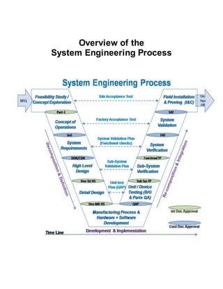
- 3. Overview ofSystem Engineering Process 3 | P a g e Compiled by: RamkumarP Systems Engineering Principles Start with Your Eye on the Finish Line You should reach consensus at the very beginning of the project on what will constitute success at the end. This means that the stakeholders should start with an agreement of what the project should accomplish and the metrics that will be used to measure the success of the project. This initial focus on the finish line must be sustained by project management as project development progresses and competing interests and project complexities begin to dominate the day-to-day work. Customer & System developer Involvement is Key Successfulprojects involve the customer, system developer (manufacturer),end-users, and other stakeholders in the project development through field implementation. Systems engineering is a systematic process that includes reviews and decision points intended to provide visibility into the process and encourage stakeholder involvement. The systems engineering process includes stakeholders through all stages of the project, from initial needs definition through system verification and acceptance. The stakeholders who are involved in any particular step will vary, providing managers,operators, and technical personnel with an opportunity to contribute to the steps in the process where their input is needed. The “V” SystemsEngineeringModel Many different process models have been developed over the years that specify a series of steps that make up the systems engineering approach. Among these models, the “V” model, shown in below Figure, is merging as the de facto standard way to represent systems engineering for our SPM projects. Since it was first developed in the 1980s, the “V” model has been refined and applied in many different industries. Wings have been recently added to the “V” as part of its adaptation to show how project development fits within the broader project life cycle. The left wing shows the feasibility studies, and concept exploration that supports initial identification and scoping of a project based on various application needs. The central core of the “V” shows the project definition, implementation, and verification processes. The right wing shows the field implementation of the system. The wings are a key addition to the model since it is important to consider the entire life cycle during project development.
- 4. Overview ofSystem Engineering Process 4 | P a g e Compiled by: RamkumarP
- 5. Overview ofSystem Engineering Process 5 | P a g e Compiled by: RamkumarP What are the Parts of the “V” Diagram FeasibilityStudy/ConceptExploration In this step: A business case is made for the project. Technical and economic feasibility is assessed; benefits and costs are estimated; and key risks are identified. Alternative concepts for meeting the project’s purpose and need are explored, and the superior concept is selected and justified. OBJECTIVES Identify superior, cost-effective concept,and document alternative concepts with rationale for selection Verify project feasibility and identify preliminary risks INPUT Sources of Information Project purpose and need (Application & UUT details) Project goals and objectives (End-of-line or performance test) Project scope/subset of the indented application (Supplier & Customer scope) PROCESS Key Activities Define evaluation criteria Perform initial risk analysis Identify alternative concepts Evaluate alternatives & Document results OUTPUT Process Results Feasibility study that identifies alternative concepts and makes the business case for the project on the selected concept REVIEW Proceed only if you have: Received approval on the feasibility study from internal departments & customer, as required includes field implementation. Reached consensus on the selected alternative concept
- 6. Overview ofSystem Engineering Process 6 | P a g e Compiled by: RamkumarP Conceptof Operations In this step: The project development team reach a shared understanding of the system to be developed and how it will be built at factory; then operated and maintained at the field. The Concept of Operations is documented to provide a foundation for more detailed analyses that will follow. It will be the basis for the system requirements that are developed in the next step. OBJECTIVES High-level identification of user needs and system capabilities in terms that all project development & implementation team can understand System builder agreement on interrelationships and roles & responsibilities for the system Shared understanding by system developers, implementation team, field installation team and end-user (customer) on the who, what, why, where,and how of the system Agreement on key performance measures and a basic plan for how the system will be validated at the end of project development INPUT Sources of Information Developer & implementation team lists, roles and responsibilities, and other components from Customer as well as system developer. Recommended concept and feasibility study from the previous step Broad Customer input and review PROCESS Key Activities Identify the stakeholders associated with the system/project Define the core group (Mech/Elect/S.W) responsible for creating the Concept of Operations Develop an initial Concept of Operations (Part-1),review with broader group of stakeholders including customer (SoS), and iterate Define customer needs Create a System Validation Plan (FAT) OUTPUT Process Results Concept of Operations describing the who, what, why, where,and how of the project/system, including stakeholder needs (including customer’s) and constraints System Validation Plan (FAT) defining the approach that will be used to validate the project on delivery REVIEW Proceed only if you have: Received approval on the Concept of Operations (Part-1) internally & SoS from Customer Received approval on the System Validation Plan (FAT) from Customer & Validation team
- 7. Overview ofSystem Engineering Process 7 | P a g e Compiled by: RamkumarP Overview The Concept of Operations (Part-1) is a foundation document that frames the overall system and sets the technical course for the project. Its purpose is to clearly convey a high-level view of the system to be developed that each stakeholder can understand. This Document can answers who, what, where,when, why, and how questions about the project from the viewpoint of each stakeholder. Who – Who are the stakeholders involved with the system? What – What are the elements and the high-level capabilities of the system? Where – What is the geographic, environmental and physical extent of the system? When – What is the sequence of activities that will be performed? Why – What is the problem or opportunity addressed by the system? How – How will the system be developed, operated, and installed?
- 8. Overview ofSystem Engineering Process 8 | P a g e Compiled by: RamkumarP System Requirements In this step: The customer needs identified in the Concept of Operations are reviewed, analyzed, and transformed into verifiable requirements that define what the system will do but not how the system will do it. Working closely with stakeholders, the requirements are elicited, analyzed, validated, documented, and base-lined. OBJECTIVES Develop a validated set of system requirements that meet the customer needs INPUT Sources of Information Concept of Operations – Part-1 (Customer needs) Functional requirements, interfaces, and applicable standards Applicable statutes, regulations, and policies Constraints (required legacy system interfaces, hardware/software platform,etc.) PROCESS Key Activities Elicit requirements Analyze requirements Document requirements Validate requirements Manage requirements (Project Plan for Design activities) Create a System Verification Plan (Functional Checks) Create a System Acceptance Plan (Performance Checks) OUTPUT Process Results System Requirements document (SoS & CDR/DDR) System Verification Plan (Functional test plan) Traceability Matrix (System Engineering Management Plan) with Project Plan System Acceptance Plan (Performance test plan) REVIEW Proceed only if you have: Received approval on the System Requirements document (CDR/DDR) from customer organization, including those that will deploy, test, install, operate,and maintain the new system Received approval on the System Verification Plan from the test team Received approval on the System Acceptance Plan from the test team Overview One of the most important attributes of a successfulproject is a clear statement of requirements that meet the customer needs. Unfortunately, creating a clear statement of requirements is often much easier said than done. The initial list of customer needs that are collected will normally be a jumble of
- 9. Overview ofSystem Engineering Process 9 | P a g e Compiled by: RamkumarP requirements, wish lists, technology preferences, and other disconnected thoughts and ideas. A lot of analysis must be performed to develop a good set of requirements from this initial list.
- 10. Overview ofSystem Engineering Process 10 | P a g e Compiled by: RamkumarP System Design (High level Design & Detail Design) In this step: A system design is created based on the system requirements including a high- level design that defines the overall framework for the system. Subsystems of the system are identified and decomposed further into components. Requirements are allocated to the system components, and interfaces are specified in detail. Detailed specifications are created for the hardware and software components to be developed, and final product selections are made for off- the-shelf components (Standards & Bought-outs). OBJECTIVES Produce a high-level design that meets the system requirements and defines key interfaces, and that facilitates development, integration, and field implementation includes future maintenance and upgrades Develop detailed design specifications that support hardware and software development and procurement of off-the-shelf equipment INPUT Sources of Information Concept of Operations (Part-1 & SoS) System Requirements document (CDR/DDR) Off-the-shelf products (Standards & Bought-outs) Existing system design documentation (Standardized design) Any other industry standards PROCESS Key Activities Evaluate off-the-shelf components Develop and evaluate alternative high-level designs Analyze and allocate requirements Document interfaces and identify standards Create Integration (Assembly) Plan, Subsystem Verification Plans, and Unit/Device test Plans Develop detailed component-level design specifications OUTPUT Process Results Off-the-shelf evaluation and alternatives summary reports High-level (architectural) design Detailed design specifications for elements, sub-systems & hardware/software Integration (Assembly) Plans, Subsystem Verification Plans, and Unit/Device Test Plans REVIEW Proceed only if you have:
- 11. Overview ofSystem Engineering Process 11 | P a g e Compiled by: RamkumarP Approved high-level design for the project Defined all system interfaces Traced the system design specifications to the requirements Approved detailed specifications for all Elements (Elect/Mech), hardware/software components Overview In the systems engineering approach, we define the problem before we define the solution. The previous steps in the “V” have all focused primarily on defining the problem to be solved. The system design step is the first step where we focus on the solution. This is an important transitional step that links the system requirements that were defined in the previous step with system implementation that will be performed in the next step. There are two levels of design that should be included in your project design activities; High-level design and Detail design.
- 12. Overview ofSystem Engineering Process 12 | P a g e Compiled by: RamkumarP Software/Hardware Developmentand Device Testing In this step: Hardware and software solutions are created for the components identified in the system design. Part of the solution may require custom hardware and/or software,and part may be implemented with off-the-shelf items, modified as needed to meet the design specifications. The components are tested and delivered ready for integration and installation. OBJECTIVES Develop and/or purchase hardware and software components that meet the design specifications and requirements with minimum defects Identify any exceptions to the requirements or design specifications that are required INPUT Sources of Information System and subsystem requirements System design Off-the-shelf products Industry standards Unit/Device Test Plans PROCESS Key Activities Plan for manufacturing process (Project Plan for manufacturing) Establish development environment (QAP,Master Production Process Document (MPP) & Methods Document) Procure off-the-shelf products Manufacturing of parts (Elect & Mech elements) Perform unit/device testing OUTPUT Process Results Complete Project plans Hardware and software components, tested and ready for integration Supporting documentation (e.g., QAP, Master Production Process Document - MPP & Methods Document and test utilities) REVIEW Proceed only if you have: Conducted technical reviews of the elements manufacturing process includes hardware/software Performed configuration/quality checks on the elements, hardware and software
- 13. Overview ofSystem Engineering Process 13 | P a g e Compiled by: RamkumarP Received all supporting documentation Verified that unit/device testing has been successfully completed Overview Although hardware and software development may be the first task that comes to mind when thinking about a project, the systems engineering approach focuses on the preceding requirements and design steps and on the integration, verification, and validation steps to follow. The systems engineering process now provides technical oversight as an implementation team of specialists fabricates the hardware and develops the software. This is a highly iterative process, particularly for software,where key features may be incrementally implemented, tested,and incorporated into the baseline over time. Manufacturing progress is monitored through a planned series of walkthroughs, inspections, and reviews.
- 14. Overview ofSystem Engineering Process 14 | P a g e Compiled by: RamkumarP Integration(Sub-Assy & FinalAssembly) and Sub-System & System Verification In this step: The elements / components are individually verified and then integrated to produce subsystems. These assemblies are also individually verified before being integrated with others to produce yet larger assemblies, until the complete system has been integrated and verified. OBJECTIVES Integrate and verify the system in accordance with the high-level design, requirements, and verification plans and procedures Confirm that all interfaces have been correctly implemented Confirm that all requirements and constraints have been satisfied INPUT Sources of Information System Requirements document (CDR/DDR) High-level design specifications Detailed design specifications (Drawings & Details – Part-2) Elements, B/Os, Hardware and software components Integration (Assembly & Alignment) plan System and Subsystem Verification Plans PROCESS Key Activities Add detail to integration and verification plans Establish integration and verification environment Perform system integration (Assembly & Alignment) Perform system verification OUTPUT Process Results Integration plan (updated) Verification plan (updated) Integration test and analysis results Verification results, including corrective actions taken REVIEW Proceed only if you have:
- 15. Overview ofSystem Engineering Process 15 | P a g e Compiled by: RamkumarP Documented evidence that the components, subsystems, and system meet the allocated requirements Documented evidence that the external and internal interfaces are working and consistent with the interface specifications Overview In this step, we assemble the system components into a working system and verify that it fulfills all of its requirements. Assembling a puzzle is a nice, simple analogy for this step, but the challenge in a custom built project “puzzle” is that you may find that not all of the pieces are available at the same time, some won’t fit together particularly well at first, and there will be pressure to change some of the pieces after you have already assembled them. The systems engineering approach provides a systematic process for integration and verification that addresses the challenges and complexity of assembling a customized first time right system.
- 16. Overview ofSystem Engineering Process 16 | P a g e Compiled by: RamkumarP System Validation In this step: After the system has passed system verification, the validation team and/or with customer representative, or another entity, runs its own set of tests to make sure that the system meets the original needs identified in the Concept of Operations (FAT in accordance with SoS). OBJECTIVES Confirm that the factory installed system meets the user’s needs and is effective in meeting its intended purpose within specified constrains INPUT Sources of Information Concept of Operations (SoS & CDR/DDR) Verified, and operational system System Validation Plan (FAT) PROCESS Key Activities Update Validation Plan as necessary and develop procedures Validate system Document validation results, including any recommendations or corrective actions OUTPUT Process Results System Validation Plan (update) and procedures Test issues and resolutions - FRACAS Validation results Final documentation and training materials Delivery and installation plan, including shipping notices Transition Plan with checklists REVIEW Proceed only if you have: Validated that the system is effectively meeting its intended purpose Documented issues/shortcomings Established ongoing mechanisms for monitoring performance and collecting recommendations for improvement Made modifications to the Concept of Operations (SoS) to reflect how the system is actually being used Overview After all, we have already verified that the system meets all of its requirements, factory installed the system and trained the users, and the customer has successfully conducted acceptance tests and formally accepted the system. Aren’t we done? The answer is: yes and no. Yes,the system can be put into operation at field and is beginning to be used for its intended purpose. No, we aren’t done. Now
- 17. Overview ofSystem Engineering Process 17 | P a g e Compiled by: RamkumarP that the system is beginning to be used in the operational environment, we have our first good opportunity to measure just how effective the system is in that environment (i.e., system validation). In systems engineering, we draw a distinction between verification and validation.Verification confirms that a product meets its specified requirements. Validation confirms that the product fulfills its intended use.
- 18. Overview ofSystem Engineering Process 18 | P a g e Compiled by: RamkumarP Field Deployment In this step: The system is installed in the operational environment and transferred from the project development team to the organization that will own and operate it. The transfer also includes support equipment, documentation, operator training, and other enabling products that support ongoing system operation and maintenance. Field Acceptance tests (SAT)are conducted to confirm that the system performs as intended in the operational environment. A transition period and warranty ease the transition to full system operation. OBJECTIVES Uneventful transition to the new system INPUT Sources of Information Integrated and verified system, ready for installation System Acceptance Plan (SAT) PROCESS Key Activities Plan for system installation and transition Deliver the system Prepare the facility (Site readiness) Install the system Perform acceptance tests (Site trials) Transition to operation (Site sign-off) OUTPUT Process Results Spares inventory Documented issues/shortcomings - FRACAS Operations and maintenance procedures (O&M Manual) Final documentation: Site Acceptance report & Site sign-off document REVIEW Proceed only if you have: Formally accepted the system at site Documented acceptance test results,anomalies, and recommendations Overview Up to this point, the system has been tested primarily in a manufacture hub (lab environment). The next step is to ship the system to the actual deployment site(s), install and check it out, and make sure the system and personnel are ready to transition to system operations and maintenance (O&M). Larger systems may be installed in stages.. In other cases,phased deployment may be performed to mitigate risk by deploying the essential core of the system and then adding features over time. If it is necessary to deploy the system in stages, whether due to funding constraints, to mitigate risk, or to synchronize with other projects, it is important to understand the dependencies between successive deployments and to prioritize the projects accordingly.
- 19. Overview ofSystem Engineering Process 19 | P a g e Compiled by: RamkumarP
- 20. Overview ofSystem Engineering Process 20 | P a g e Compiled by: RamkumarP Project Management Processes In addition to the process steps identified in the “V”, there are severalproject management and control activities that are essential in order for a project to be successful. The project planning, project monitoring and control, and risk management processes all support systems engineering. Project Management Activities Cut Across All Steps of the “V”
- 21. Overview ofSystem Engineering Process 21 | P a g e Compiled by: RamkumarP ProjectPlanning Project planning lays out the activities, resources, budget, and timeline for the project. This effort, which begins early in the project life cycle, results in the creation of two major plans, the Project Plan (PP) and the Systems Engineering Management Plan (SEMP). Project Plan The Project Plan (PP) documents how the project will be managed and controlled from a programmatic standpoint. It identifies the detailed work plans for both administrative and technical tasks. For each project task,the PP documents what is to be done, by whom, with what, when, how (processes to be used), and dependencies. Systems Engineering Management Plan The Systems Engineering Management Plan (SEMP) is the top-level plan for managing the systems engineering effort to produce a final operational system from initial requirements. Just as the PP defines how the QCD of overall project will be executed, the SEMP defines how the engineering portion of the project will be executed and controlled. It describes how the efforts of system designers, test engineers, and other engineering and technical disciplines will be integrated, monitored, and controlled during the complete life cycle. For a small project, the SEMP might be included as part of the PP document,but for any project of greater size or complexity a separate document is recommended. ProjectMonitoring and Control The plans discussed in the PP and in the SEMP include the steps that will be taken to monitor and control the project from a systems engineering standpoint. Two aspects of this monitoring and control, project tracking and project technical reviews, are discussed next. Project Tracking The PP and the SEMP define the tasks and schedule for the project and the processes that will be followed to produce the deliverables. Once the project is underway, how can you track progress against the plan? When should you start to worry that the project is veering off track? Is the project on track as long as cost and schedule are meeting the plan? It’s tough to answer any of these questions without creating some means of measuring progress. Project Reviews Project reviews provide a structured and organized approach to reviewing project products to determine if they are fit for their intended use. These reviews are a primary method of communicating progress, monitoring risk, and transferring products and knowledge between project team members. The reviews often occur at the completion of a “V” process step and represent decision points that must be passed successfully before moving to the next step in the process. Risk Management Risk management is the identification and control of risks during all phases of the project life cycle. Murphy’s Law is alive and well during most projects, so it’s essential that you anticipate the risks and put plans in place for addressing them. The goal of risk management is to identify potential problems before they occur, plan for their occurrence,and monitor the system development so that early action can be taken if the risk occurs. Risk Identification The objective of the risk identification step is to identify the key risks to project success at the beginning of the project. This will require that project managers, project development team,
- 22. Overview ofSystem Engineering Process 22 | P a g e Compiled by: RamkumarP project implementation team, project validation team and possibly outside experts brainstorm about where the risks may lie. They should take a look at all potential risks, from initial development all the way out through operations and maintenance and eventual retirement of the system. Risk Analysis and Prioritization Once risks have been identified, the next step in the process is to analyze and prioritize them by determining the impact should the risk occur, and the probability of its occurrence. Howsevere will the impact be ifthe risk occurs? For each risk identified, you should make an assessment of what will be impacted if the risk occurs. Risks typically fall into one or more of the following areas: • Technical (risks affecting the quality of the resulting system) • Schedule (risks that cause schedule slippage) • Cost (risks that cause cost to exceed budget) What is the probability that the risk will occur? For each risk identified, assign a probability that the risk will occur (e.g.,high, medium, or low). It’s a good idea to define each of these probabilities quantitatively to make sure that everyone is analyzing the risks the same way (e.g.,high = greater than 30% probability that the risk will occur). Risk Mitigation The objective of risk mitigation is to identify and evaluate alternatives for handling the risks identified. From a project management standpoint, there are severalways to address risks: Avoid the risk altogether (e.g., change in requirements or design) Take actions to reduce the likelihood or severity of the risk (e.g.,prototype a new technology or develop and deliver software incrementally) Accept the risk and do nothing, which is often the approach for risks with low impact and low probability of occurrence Risk Monitoring Risks should be monitored throughout the life cycle to determine whether the mitigation steps are actually lessening the severity or probability of each risk. It’s also possible that the nature of the risk has changed (e.g., the due date for delivery of the software code was extended because another project was delayed).