Let-off Motion | Weaving Technology
•Descargar como DOCX, PDF•
0 recomendaciones•1,080 vistas

> Objective of Let-off Motion > Loom Drive/ Power Development

Recomendados
Recomendados
Más contenido relacionado
La actualidad más candente
La actualidad más candente (20)
Similar a Let-off Motion | Weaving Technology
Similar a Let-off Motion | Weaving Technology (20)
Más de Md Rakibul Hassan
Más de Md Rakibul Hassan (20)
Último
Último (20)
Let-off Motion | Weaving Technology
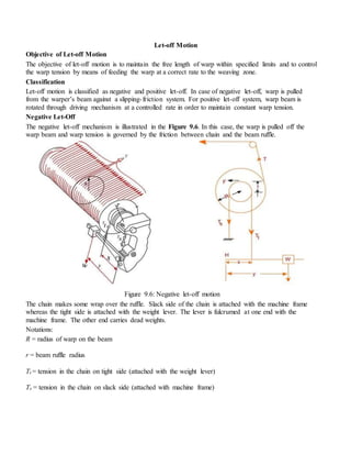
- 1. Let-off Motion Objective of Let-off Motion The objective of let-off motion is to maintain the free length of warp within specified limits and to control the warp tension by means of feeding the warp at a correct rate to the weaving zone. Classification Let-off motion is classified as negative and positive let-off. In case of negative let-off, warp is pulled from the warper’s beam against a slipping-friction system. For positive let-off system, warp beam is rotated through driving mechanism at a controlled rate in order to maintain constant warp tension. Negative Let-Off The negative let-off mechanism is illustrated in the Figure 9.6. In this case, the warp is pulled off the warp beam and warp tension is governed by the friction between chain and the beam ruffle. Figure 9.6: Negative let-off motion The chain makes some wrap over the ruffle. Slack side of the chain is attached with the machine frame whereas the tight side is attached with the weight lever. The lever is fulcrumed at one end with the machine frame. The other end carries dead weights. Notations: R = radius of warp on the beam r = beam ruffle radius Tt = tension in the chain on tight side (attached with the weight lever) Ts = tension in the chain on slack side (attached with machine frame)
- 2. W= weight x = the distance between fulcrum point and chain on tight side y = the distance between fulcrum point and weight (variable) T = tension in the warp sheet (variable) F = frictional force at the beam ruffle Taking moments about the beam centre we have: T R = F r The frictional force F =Tt - Ts where μ= coefficient of friction between chain and beam ruffle and θ = angle of wrap in radian made by the chain on beam ruffle. Now, taking moments about the fulcrum H of the lever, we have: Equation 5 shows that the condition needed to achieve a constant warp tension is to maintain the ratio constant. Thus as beam radius R reduces, the distance y must be reduced by moving the weight towards the fulcrum H in regular interval to balance the warp tension. For example, if the beam radius decreases by 25%, the distance y must be reduced by 25% to maintain a constant warp tension. As shown in Figures 9.7, the warp tension is maintained within a small range from full beam to empty beam by shifting the weights at regular intervals. It is also noted that the frequency of weight shifting increases towards the beam is getting exhausted. This is ascribed to the asymptotic relationship between warp tension and warp radius on the beam. Hypothetical Example Let the initial diameter of the warper’s beam is 100 cm. The allowable increase in warp tension is 25% of
- 3. nominal level. So, when the beam diameter will be 80 cm, the warp tension will increase by 25%. The weaver will adjust the position of the weight so that the tension will come back to nominal level. In second step, when the beam diameter will reduce to 64 cm, the warp tension will again increase by 25%. Therefore, first weight shifting will be done after 20 cm reduction in beam diameter whereas the second weight shifting will happen after 16 cm reduction in beam diameter. So, as the beam weaves down the shifting of weight will be more frequent. Figure 9.7: Warp tension vs. beam radius Positive Let-off In case of positive let-off warp, the warp tension is controlled by a mechanism which drives the warp beam at a correct rate. In most of the positive let-off systems, the backrest is not fixed but floating. It acts as a warp tension sensing mechanism. As the tension in the warp increases, the backrest is depressed. A Hunt positive let-off motion is ilustrated in the Figure 9.8. There are two split pullyes made out of V- pulley. Motion from crank shaft moves the top split pulley via a worm and worm wheel. Top pulley in turn drives the bottom pulley through a belt. As the tension on the warp increases the back rest goes down and the L-type lever with weight lowers the diameter of the bottom pulley and essentially increases the diameter of the top pulley through the necessary linkages. Now the bottom pulley moves at a faster rate than it was earlier and the connecting worm to the beam drive moves more to deliver extra warp in order to reduce the warp tension.
- 4. Figure 9.8: Hunt positive let-off motion
- 5. Loom Drive/Power Development: Hand Loom: HumanPowerDrive Power Loom: I. OrdinaryPowerLoom- Water wheel Steamengine Diesel engine Electricmotor II. ElectricPowerLoom- Large commonmotor Group motor Individual motor a) DirectDrive (directfrommotorto device) b) Indirectdrive (usedincone,cheesewinding) Multiple motor #. Method of drive:Loomsare drivenbythe following2ways- Individual drive Group drive #. Advantagesof individual drive: Lesspowerloss Stoppage of only1 m/c Productionismore Efficiencyismore Lesshazard of workingwithm/c Layout of loomisveryeasy #. Disadvantagesof individual drive: Highwheel cost Highmaintenance cost #. Advantagesof groupdrive:
- 6. Lessinitial investment Economical withrespecttofixedcharges&maintenance #. Disadvantagesof groupdrive: Shafts,pulleys,beltsetcare absorbgreaterpower Efficiencyislower Productionislow In case of motorfailure all loomsare stopped It givesclumsyappearance &more chance of accident Layout isdifficult