
Recomendados
Recomendados
Más contenido relacionado
La actualidad más candente
La actualidad más candente (20)
Similar a Informatica cloud Powercenter designer
Similar a Informatica cloud Powercenter designer (20)
Último
Último (20)
Informatica cloud Powercenter designer
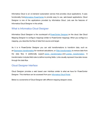
- 1. Informatica Cloud is an on-demand subscription service that provides cloud applications. It uses functionality fromInformatica PowerCenter to provide easy to use, web-based applications. Cloud Designer is one of the applications provided by Informatica Cloud. Lets see the features of Informatica Cloud Designer in this article. What is Informatica Cloud Designer Informatica Cloud Designer is the counterpart of PowerCenter Designer on the cloud. Use Cloud Mapping Designer to configure mappings similar to PowerCenter mappings. When you configur e a mapping, you describe the flow of data from source and target. As it is in PowerCenter Designer you can add transformations to transform data, such as an Expression transformation for row-level calculations, or Filter transformation to remove data from the data flow. It additionally support Joiner transformation and LookUp transformation. A transformation includes field rules to define incoming fields. Links visually represent how data moves through the data flow. Cloud Designer Interface Cloud Designer provides a web based user interface similar to what we have for PowerCenter Designer. This interface can be accessed from your Informatica Cloud Portal. Below is a screenshot of Cloud Designer with different mapping designer areas.
- 2. 1. Mapping Canvas :- The canvas for configuring a mapping, which is similar the workspace what we have for PowerCenter Designer. 2. Transformation Palette :- Lists the transformations that you can use in the mapping. You can add a transformation by clicking the transformation name. Or, drag the transformation to the mapping canvas. 3. Properties Panel :- Displays configuration options for the mapping or selected transformation. Different options display based on the transformation type. This is similar to different tabs available in PowerCenter Transformations. 4. Toolbar :- Provides different options such as Save, Cancel, Validate, Arrange All icon, Zoom In/Out. 5. Status Area :- Displays the status of the mapping and related tasks. It indicates if the mapping includes unsaved changes. When all changes are saved, indicates if the mapping is valid or invalid. Transformations On Cloud Designer
- 3. Transformations are a part of a mapping that represents the operations that you want to perform on data. Transformations also define how data enters each transformation. The Mapping Designer provides a set of Active and Passive transformations. 'Joiner' and 'Filter' are the two active transformations available. 'Expression' is passive transformation and 'LookUp' transformation act as passive when returning one row and active when returning more than one row. Additionally designer supports 'Source' and 'Target' transformations to read and write data from different sources and targets. Transformation Type Description Source N/A Reads data from a source. Target N/A Writes data to a target. Joiner Active Joins two sources. Filter Active Filters data from the data flow. Expression Passive Modifies data based on passive expressions. Lookup Passive when returning one row. Active when returning more than one row. Looks up data from a lookup object. Defines the lookup object and connection, as well as the lookup condition and return values. Mapping Configuration Task
- 4. Mapping Configuration Task is similar to a session task in PowerCenter. The Mapping Configuration Task allows you to process data based on the data flow logic defined in a mapping. When you create a mapping configuration task, you select the mapping for the task to use, just like you choose a mapping while you create a session task in PowerCenter. You also define the parameter value associated with the mapping. Below shown is the different options you need to set for the Mapping Configuration. Task Flows Task Flows are similar to a workflows in PowerCenter. You can create a task flow to group multiple tasks and run them in a specific order. You can run the task flow immediately or on a schedule. The task flow runs tasks serially, in the specified order. Below shown is the different options you need to set for the Mapping Configuration.
- 5. How Cloud Designer is Different Cloud Designer is not a replacement for PowerCenter Designer, but to provide more advanced data integration capability on the cloud. There are few interesting features available with Cloud Designer, which is not available in PowerCenter Designer. 1. Dynamic Field Propagation
- 6. Unlike PowerCenter Designer, you do not have to connect all the ports manually between transformations. It uses logical rules to propagate fields or ports from one transformation to other transformation. Possible options for logical field mapping. Include All Fields. Include/Exclude Field by specific names. Include/Exclude Fields by Data Types. Include/Exclude Fields by name patterns. Below shown is the screenshot of available options for logical field mapping. This option is available in the "Property Panel". It helps the mapping to self-adapts to source or target structure changes. For example if you use “All Fields” brings in newly added fields dynamically into the mapping. 2. Parameterized Templates A parameter is placeholder for a value or values in a mapping. The Cloud Designer can be used to build reusable mappings that include parameterized values. This can be configured to create an integration workflow with specific business parameters entered at runtime. You define the value of the parameter when you configure the mapping configuration task. as mentioned above paragraph. Parameterization along with dynamic field propagation, makes the mapping build on cloud extremely reusable templates.
- 7. In the last couple of articles we discussed the basics of Informatica Cloudand Informatica Cloud Designer. In this tutorial we describe how to create a basic mapping, save and validate the mapping, and create a mapping configuration task. The demo mapping reads and writes data sources, also include the parameterization technique. The mapping we create here reads source data, filters out unwanted data, and writes data to the target. The mapping also includes parameters for the source connection and filter value. For this tutorial, you can use a sample Account source file available in the Informatica Cloud Community. You can download the sample source file from the following link Sample Source File for the Mapping Tutorial. Step 1. Mapping Creation and Source Configuration The following procedure describes how to create a new mapping and configure the sample Account flat file as the source. 1. To create a mapping, click Design > Mappings > New Mapping. 2. In the New Mapping dialog box, enter a name for the mapping: Account_by_State. You can use underscores in mapping and transformation names, but do not use other special characters.
- 8. 3. To add a source to the mapping, on the Transformation Palette, click Source. 4. In the Properties Panel, on the General tab, enter a name for the source: FF_Account. 5. On the Source tab, configure the following properties: o Connection :- Source connection. Select the flat file connection for the sample Account source file. Or, create a new flat file connection for the sample source file. o Source Type :- Source type. Select Object.
- 9. o Object :- Source object. Select the sample Account source file. To preview source data, click Preview Data. 6. To view source fields and field metadata, click the Fields tab. 7. To save the mapping and continue, on the toolbar, click Save > Save and Continue. Step 2. Filter Creation and Field Rule Configuration In the following procedure, you add a Filter transformation to the data flow and define a parameter for the value in the filter condition. When you use a parameter for the value of the filter condition, you can define the filter value that you want to use when you configure the task. And you can create a different task for the data for each state. The sample Account source file includes a State field. When you use the State field in the filter condition, you can write data to the target by state. For example, when you use State = MD as the condition, you include accounts based in Maryland in the data flow.
- 10. 1. To add a Filter transformation, on the Transformation palette, drag a Filter transformation to the mapping canvas. 2. To link the Filter transformation to the data flow, draw a link from the FF_Account source to the Filter transformation. When you link transformations, the downstream transformation inherits fields from the previous transformation. 3. To configure the Filter transformation, select the Filter transformation on the mapping canvas. 4. To name the Filter transformation, in the Properties panel, click General and enter the name: Filter_by_State. 5. To configure field rules, click Incoming Fields. Field rules define the fields that enter the transformation and how they are named. By default, all available fields are included in the transformation. Since we want to use all fields, do not configure additional field rules. 6. To configure the filter condition, click Filter. 1. To create a simple filter with a parameter for the value, for Filter Condition, select Simple. 2. Click Add New Filter Condition. 3. For Field Name, select State, and use Equals as the operator.
- 11. 4. For Value, select New Parameter. 5. In the New Parameter dialog box, configure the following options and click OK. 1. Name: FConditionValue 2. Display Label: Filter Value for State 3. Description: Enter the two-character state name for the data you want to use. 4. Default Value: MD. Notice, you can only create a string parameter in this location. 7. To save your changes, click Save > Save and Continue. Step 3. Target and Source Parameter Configuration
- 12. In the following procedure, you configure the target, then replace the source connection with a parameter. Because you plan to parametrize the source, you also need to use a parameter for the field mapping. 1. To add a Target transformation, on the Transformation palette, drag a Target transformation to the mapping canvas. 2. To link the Target transformation to the data flow, draw a link from the Filter transformation to the Target transformation. 3. Click the Target tab and configure the following properties: 1. Connection :- Target connection. Select a connection for the target. Or, create a new connection to the target. Target Type :- Target type. Select Object. 2. Object :- Target object. Select an appropriate target. 3. Operation :- Target operation. Select Insert. 4. To configure the field mapping, click Field Mapping. 5. To map some fields and allow the remaining fields to be mapped in the task, configure the Field Map Option for Partially Parametrized.
- 13. 6. Create a New Parameter and configure the following properties. 1. Name: PartialFieldMapping. 2. Display Label: Partial Field Mapping. 3. Select Allow partial mapping override. This allows you to view and edit mapped fields in the task. When want to prevent the task developer from changing field mappings configured in the mapping, clear this option.
- 14. 7. Map the fields that you want to show as mapped in the task. 8. Click Save > Save and Continue. 9. To edit the source to add a parameter for the source connection, click the FF_Account Source transformation, and then click the Source tab. 10. For Connection, click New Parameter. 11. In the New Parameter dialog box, configure the following parameter properties. 1. Name: SourceConnection. 2. Display Label: Sample Flat File. 3. Description: Select the connection to the sample file.
- 15. Below shown is the completed mapping. Step 4. Mapping Validation and Task Creation In the following procedure, you save and validate the mapping. And you create a mapping configuration task based on the mapping. 1. To validate the mapping, click Save > Save and Continue. o When you save the mapping, the Mapping Designer validates the mapping. The mapping is valid when the Status in the status area shows Valid. o If the status is Invalid, in the toolbar, click the Validation icon. In the Validation panel, click Validate.
- 16. o The Validation panel lists the transformations in the mapping and the mapping status. The mapping should be valid. If errors display, correct the errors. Click Validate to verify that errors are corrected. 2. To create a task based on the mapping, click Save > Save and New Mapping Configuration Task. The Mapping Configuration Task wizard launches as shown below. 3. On the Definition page, enter a name for the task: Mapping Tutorial and give your Secure Agent. Notice, the task uses the mapping that you just completed.
- 17. 4. Click Next. On the Sources page, the source parameter displays. Notice, the tool tip for the connection displays the parameter description. For Sample Flat File, select the source connection to the sample file, andclick Next. o Notice, the Targets page does not display because the target connection and object is defined in the mapping. o The Other Parameters page displays the remaining parameters for the mapping. 5. In the Partial Field Mapping parameter, map the target fields that you want to use.
- 18. o Note that because you allowed partial mapping override, the Target Fields list displays all fields. You can keep or remove the existing links. 6. For the Filter Value for State parameter, delete the default value, MD, and enter TX.
- 19. 7. To save and close the task, click Save > Save and Close. In the next step you can schedule the mapping on a predefined schedule. Hope you guys enjoyed this article. We are curious to know about your feedback.