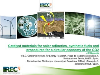
Catalyst materials for solar refineries, synthetic fuels and procedures for a circular economy of the CO2.
•
2 recomendaciones•321 vistas

Plenary lecture given by Joan Ramón Morante (IREC) at the XVII B-MRS Meeting, in Natal (Brazil), on September 20, 2018.

Recomendados
Recomendados
Más contenido relacionado
La actualidad más candente
La actualidad más candente (19)
Similar a Catalyst materials for solar refineries, synthetic fuels and procedures for a circular economy of the CO2.
Similar a Catalyst materials for solar refineries, synthetic fuels and procedures for a circular economy of the CO2. (20)
Más de Sociedade Brasileira de Pesquisa em Materiais
Más de Sociedade Brasileira de Pesquisa em Materiais (20)
Último
Último (20)
Catalyst materials for solar refineries, synthetic fuels and procedures for a circular economy of the CO2.
- 1. Catalyst materials for solar refineries, synthetic fuels and procedures for a circular economy of the CO2 J.R.Morante IREC, Catalonia Institute for Energy Research, Plaça de les Dones de Negre,1. Sant Adrià del Besòs, 08930. Spain. Department of Electronics, University of Barcelona, C/Martí i Franquès,1. Barcelona,08028. Spain. H2 O2
- 2. Nowadays, the circular economy of carbon dioxide constitutes one of the major world challenges. Climatic change CO2 emissions
- 3. The conversion of CO2 into value-added chemicals and/or fuels, using renewable energy and earth-abundant elements as well as environmental friendly materials is a key priority.
- 5. Carbon dioxide closed loop in which this molecule is captured, reduced and oxidized continuously defining an ideal circular economy of the CO2 Fossil gas CO2 emissions Methanation based on Paul Sabatier reactor.
- 7. Carbon dioxide reduction by thermochemical or plasma procedures which are open new alternatives to the methanation process Patent: P201530109 300mg of catalyst, corresponding to an GHSV of 20000, the reactor is supplied with a mixture of carbon dioxide and hydrogen (20% vol CO2) with a total flow rate of 12000 ml/h), at atmospheric pressure and at temperature of 20°C Journal of CO₂ Utilization 26 (2018) 202–211
- 8. EELS chemical composition maps obtained from the red rectangled area of the STEM-HAADF micrograph. Individual Ce (red), Zr (green) and Ni (blue) maps and their composite. It should be noted here that we have normalized the intensity values of the maps to that of Ce to have a better comparison
- 9. Mesoporous
- 11. Bioconversion: Synthetic natural gas production from biogas in a waste water treatment plant In collaboration with Naturgy programa RIS3CAT ENERGY CONVERSION AND MANAGEMENT 162 pp 218-224 (2018)
- 12. Demonstration unit [Sabadell (Barcelona) Spain) Digestor GasometerBiogas
- 13. Methanation unit CO2 + 4H2 –> CH4 + 2H2O Alkaline electrolyzer 37 kWh Biogas source (55-65% CH4) H2S cleaning CH4 CO2 CO2 source 10 Nm3/h
- 14. Methanation reactors Compact reactor technology Quick start-up and shut-down times Load-flexibility T depends on time, length T < 500ºC High technology
- 15. Injectable conditions in the gas pipeline are achievable in Sabadell stream H2 CH4 CO2 XCO2 % % % % inlet 66 - 33 0 middle 30 65 10 90,85 outlet 4,4 95,4 0,2 99,77 Electric consumption SNG production Efficiency PtG XCO2 kWh Nm3/h kWh/Nm3 kWout/kWin % Test 1 16,24 0,577 28,15 38,06 96,99 Test 2 15,84 0,536 29,58 36,13 97,75 Test 3 12,16 0,519 23,00 46,55 97,61 kWout/kWin > 50% can be achieved within this project 85-95% power consumption comes from hydrogen production, nevertheless surplus renewal energy production can be used. Performant catalysts are the clue
- 16. Fin de semana Intermedia Carga Punta Base Eólica Fotovoltaica Demanda Solar concentración Carga 21% RENEWABLE SURPLUS OF ENERGY ENERGY CONSUMPTION DURING A WEEK 60% renovables WIND ENERGY SOLAR ENERGY WITHOUT RENEWABLES
- 18. Source: IRES (Fraunhofer presentation) + IREC
- 19. Methanation: Solar Hydrogen +CO2 Renewable energy +feed stocks (H2, CO2) 100% Feed stocks managements 95% Efficiency 95%; loss 5% Methanation 76% Efficiency 80%; loss 19% Compressor, storage and CH4 pipe 74,5% Efficiency 98,5%; loss 1.5% Gas transport (500Km) Efficiency 99,55%, loss 0,37% 74,1% Methanation: Solar Hydrogen+CO2
- 21. Carbon dioxide reduction by electrochemical (dark and photo) procedures NEW RESEARCH ALTERNATIVE DARK PHOTO Reduced CO2 products High current densities Centralizer electrolyzer. Current densities of PV cell. Distributed electrolyzer. Future depends on cost and social acceptation
- 22. Dark Under illumination PHOTO EFFECT Two challenges: • Current density • Bias reduction
- 23. efficient solar induced bias free working mode of a PEC cell If curves intersect, there is enough potential for bias free working mode of the cell. All that matters is the current Jop at the intersection. Source: several+IREC E red E oxd
- 24. Hybrid photoanode-photocathode device for bias-free water splitting Photoanode: Hematite, TiO2 Photocathode: • a-Si:H tandem with Ni as HER catalyst • a-Si:H/a-Si:H/µc-Si:H triple with Ni catalys Electrolyte: 1M NaOH Stability of stand-alone hybrid Hematite/Tandem device 2-electrode config. 0 V applied biashematite a-Si:H tandemO2 H2 To be published
- 25. Data source: F. Urbain et al. 2016&2018
- 26. System consists of two polymer electrolyte membrane electrolysers in series with one InGaP/GaAs/GaInNAsSb triple-junction solar cell, which produces a large-enough voltage to drive both electrolysers with no additional energy input. The system achieves a 48-h average STH efficiency of 30% Nat Comm 2016,7,13237 Very expensive Use scarce materials.
- 27. The TiO2-protected III–V tandem device exhibited a solar-to-hydrogen conversion efficiency, STH, of 10.5% under 1 sun illumination, with stable performance for > 40 h Energy Environ. Sci., 2015, 8, 3166
- 28. 0.0 0.1 0.2 0.3 0.4 0.5 0.6 0.7 0.8 0 5 10 15 20 IBC UPC +Ni epox + Ni/Pt PEC H2SO4 IBC UPC +Ni epox + Ni/Pt PV HC-STH(%) E (V vs RHE) 50cm2 area 0,650 40mA/cm2 STH >15% PATENT:15382658.1 PEC PV ACS APPLIED MATERIALS & INTERFACES 10 (16) pp: 13425-13433 (2018) Our results:
- 30. Photons Fuel Added Value Chemicals Solar heat Solar electricity H2O pipeline CO2 pipeline Activation Mechanisms for H2O and CO2 reduction Fossil fuel power plant Fischer Tropsch Water Thermo-chemical Thermolysis Photolysis Photo-catalysis CO2 Capture Photo-electro-chemical Electro-chemical Solar Refinery Chemical Storage & CO2 Circular Economy biogenic carbon
- 31. Electrolyzers/ Co-electrolysis . 12-20% >10% < 65% operation Solar fuels <1€/Wp <6c€/kWh < 6c€/Kwh photons electrons chemicals Data source: IREC
- 32. centralized or distributed Where and how to install the electrochemical part? 20% 19% 11% 20% > 17% > 17%
- 33. ELECTRICIDAD GAS
- 34. Overpotentials at several tens of mA/cm2 ? Overpotentials at several tens of A/cm2 ? Electrodes: Voltage cell: LHV 1,23/1,5 ~ 82% HHV 1,48/1,5 ~ 98% 1,23/2,3 ~ 55% Less transportation losses Example considering H2
- 35. PEC/EC ANODEEC CATHODE 3D Nanostructured Cathode with Catalyst Strong interest in having back illumination especially for replacing electroreduction by photoelectroreduction of CO2. ELECTROCHIMICA ACTA 240 pp 225-230 (2017) For CO2: Cathode with appropriate catalyst Anode with excellent OER.
- 36. The final energy balance as well as the overall efficiency and productivity depend, aside of the system design constraints, of parameters as the over-potential values, charge transfer resistances linked to the role played by the catalyst. ELECTROCHIMICA ACTA 240 pp 225-230 (2017) PATENT: P3146EP00 PEC system for solar fuels
- 37. Carbon dioxide can give rise to different reduction reactions pathways with several sub products. . CO2 Reduction Products CO2 + 2e- •CO2 - CO2 + 2H+ + 2e- HCOOH CO2 + 2H+ + 2e- CO + H2O CO2 + 4H+ + 4e- HCHO+ H2O CO2 + 6H+ + 6e- CH3OH+ H2O CO2 + 8H+ + 8e- CH4 + 2H2O 2H2O + 4h+ O2 + 4H+ 2H+ + 2e- H2
- 38. CO2 Electrocatalysts reduce the overpotential of reactions through formation of intermediates. Therefore, elucidating the intermediates is a crucial requirement for rational design of novel catalysts that overcome the current limitations. So, one of the objective must tackle this knowledge gap by high-risk–high-gain approaches to prepare catalytic intermediates on oxides
- 39. CO2 reduction by metal electrocatalysis *Source : J. Chem. SOC., Faraday Trans. I, 1989, 85(8), 2309-2326 Chem. Asian J. 2009,4, 1516-1523 Stabilization of CO2 •– intermediate = high energy efficiency. Three groups depending on the binding strength + High HER overpotential CO desorption before reduction + Low HER overpotential HCOOH formation Weak CO adsorption Strong CO adsorption + Low HER overpotential CO poisoning Optimum CO adsorption CO reduction Intermediate steps of CO2R i.e. protonation *CHO or *COH 2 1 3 1
- 40. Gas Diffusion Electrodes Electrolyte Planar Planar electrode Gas diffusion electrode Catalyst particles Electrolyte CO2 chamber GDE • Active surface area ≈ geometric surface area • Limited CO2 solubility = Mass transfer problem • Active surface area >> geometric surface area • Improved CO2 transfer = overcome solubility problem
- 41. Toray Carbon Paper TGP-H-60 after Cu deposition JOURNAL OF PHYSICAL CHEMISTRY C 119 ,33 , pp18835-18842 (2015)
- 42. fibers after deposition of Sn APPLIED CATALYSIS B-ENVIRONMENTAL 150 pp 57-62 (2014) INTERNATIONAL JOURNAL OF HYDROGEN ENERGY 38,7, 2979-2985 (2013) APPLIED PHYSICS LETTERS 99 ,26 ;262102 (2011)
- 43. Electrodeposited Sn in GDE E. Irtem, J.R. Morante, et al. J. Mater. Chem. A. 2016, 4, 13582. Dark Electrolysis Sn catalyst Formic acid
- 44. Dark Electrolysis Sn catalyst Formic acid • F.E.% HCOO− = 71 ± 1.1 % • F.E.% HCOO− + CO = 82 ± 2.0 % of total CO2 conversion (CO: 6 ± 4.5 %) • Low Tafel slope value = faster charge transfer of CO2 reduction on Sn-GDE • Evidence of a rapid transfer of the initial electron • Evidence of a different rate determining step = concurrent proton−electron uptake 𝑭. 𝑬. % = 𝑛 · 𝐹 · [𝐶 𝐼 · 𝑡 -0.4 -0.6 -0.8 -1.0 -1.2 0 20 40 60 80 100 HCOO CO E (VRHE ) FaradaicEff.(%) H2 -2 -1 0 -0.3 -0.4 -0.5 -0.6 -0.7 H2 254 mV dec -1 E(VRHE ) log ji (mAcm-2 ) -3 -2 -1 0 -0.4 -0.5 -0.6 -0.7 HCOO 89 mVdec-1 CO 78 mVdec-1 E(VRHE ) log ji (mAcm-2 ) E. Irtem, J.R. Morante, et al. J. Mater. Chem. A. 2016, 4, 13582.
- 45. 100 1000 10000 10 100 1000activity(mol/(g*s)) grain radius (nm) Pulsed Electro Deposition different duty cycle Continuous Electrodeposition different samples slope -1 Using other catalysts for formic acid submitted
- 46. JOURNAL OF MATERIALS CHEMISTRY A , 4, 35, pp 13582-13588 (2016)
- 47. CO2 + 2e- •CO2 - CO2 + 2H+ + 2e- HCOOH CO2 + 2H+ + 2e- CO + H2O CO2 + 4H+ + 4e- HCHO+ H2O CO2 + 6H+ + 6e- CH3OH+ H2O CO2 + 8H+ + 8e- CH4 + 2H2O 2H2O + 4h+ O2 + 4H+ 2H+ + 2e- H2 CO2 Reduction Products Syngas H2:CO ratio 3:1 Ammonia 2:1 Methanol 1:1 Oxo products 1:0 Hydrogen ... ... ...
- 48. CO2 Reduction Catalysts Zn J. Lee, et al. Chem. Asian J. 2009, 4, 1516-1523. Syngas
- 49. Electrodeposition of Zn on Cu Foam bare Cu foam 1M ZnSO4 Cu foam coated with ZnZn flakes CE foam
- 50. Structural Analysis of Zn Flakes Zn ZnO Zn
- 51. High activity towards CO2 reduction Electrochemical Characterization after 1 h electrolysis Good stability in 0.5 M KHCO3 F. Urbain, J.R. Morante, et al. Energy Environ. Sci. 2017, 10, 2256. J.R. Morante et al. Energy and Environmental Science10(10), pp. 2124-2136 (2017)
- 52. 5:1 ≥ H2:CO ≥ 0.5:1 FEmax (CO) = 85 % jCO = 39.4 mA/cm2 Electrochemical Characterization F. Urbain, J.R. Morante, et al. Energy Environ. Sci. 2017, 10, 2256.
- 53. CO2 Reduction Catalysts Zn J. Lee, et al. Chem. Asian J. 2009, 4, 1516-1523. Syngas
- 57. ACS applied materials and interfaces (2018) ENERGY & ENVIRONMENTAL SCIENCE 10 , 10, 2256 (2017)
- 58. Dark and Solar CO2 Reduction Device Role of the anode
- 59. V [H2(g)] [CO(g)] e- h+ OH- Na+ O2 Working Mode of Stack Flow Cell CATHODE | CO2 reduction reaction (CO2R) CO2 aq. +2H+ + 2e− ⟶ HCOOH(aq.) ANODE | H2O oxidation reaction (OER) H2O l ⟶ 2H+ + 1 2 O2 g + 2e− CELL REACTION 𝐂𝐎 𝟐 𝐠 + 𝐇 𝟐 𝐎 𝐥 ⟶ 𝐇𝐂𝐎𝐎𝐇(𝐚𝐪.) + 𝟏 𝟐 𝐎 𝟐 𝐠 Gas Pure CO2 0.5 M NaHCO3 0.1 M KHCO3 0.1 M KHCO3 0.5 M KOH 0.1 M KHCO3 0.1 M KOH Membrane Catholyte AnolyteNafion (CEM/Na+) Selemion (AEM/OH-) Nafion (CEM/Na+) Sn-GDE Cu-GDE Cathode Metal oxide as TiO2 NRs/FTO or Other PV materials and nanostructures Anode ELECTROCHIMICA ACTA 240 pp 225-230 (2017)
- 60. 0,0 0,4 0,8 1,2 1,6 2,0 5 10 15 20 25 30 35currentdensityj[mA/cm2 ] 0.5 m KOH 20 mV/s potential E vs. RHE [V] Energy Environ. Sci., 8, 3242-3254, (2015) ACS Appl. Mater. Interfaces, 2016, 8, 4076 SOLAR ENERGY MATERIALS AND SOLAR CELLS 158 pp. 184-188 (2016) ACS CATALYSIS 8, 4, pp3331-3342 (2018) JOURNAL OF PHYSICALCHEMISTRY C 122,6,pp 3295-3304 (2018) ENERGY&ENVIRONMENTAL SCIENCE 10, 10, 2124(2017) ACS APPLIED MATERIALS& INTERFACES 9 ,21,17932 (2017) SOLAR ENERGY MATERIALS AND SOLAR CELLS 159 ,456-466 (2017) APPLIED CATALYSIS B-ENVIRONMENTAL 189 pp133-140 (2016)
- 61. DARK LIGHT JOURNAL OF PHYSICS D-APPLIED PHYSICS 50 ,10, 104003 (2017) JOURNAL OF MATERIALS CHEMISTRY A 4 ,42, pp 16706-16713 (2016) JOURNAL OF MATERIALS CHEMISTRY A 2 ,32, pp 12708-12716 (2014)
- 62. CoFe nanoparticles are prepared by 1 mmol Iron acetylacetonate 1mmol Cobalt acetylacetonate , 10 ml oleylamine, 1.0 ml oil acid mixed in a three-neck flask. The solution was increased to 80 °C and degased for 1hour. Then the temperature was increased to 230°/ 300º with continuously nitrogen pumping and maintained at the selected temperature for 0.5 h. After reaction, the received samples were thoroughly purified by precipitation and redispersion steps. CHEMSUSCHEM 11, 1, pp 125-129 (2018) JOURNAL OF THE AMERICAN CHEMICAL SOCIETY 138, 49 pp 16037-16045 (2016) ACS APPLIED MATERIALS & INTERFACES 8, 43,pp 29461-29469 (2016) ACS APPLIED MATERIALS & INTERFACES 8,27,pp 17435-17444 (2016)
- 64. 0 2 4 6 8 20 30 40 50 60 70 80 90 100 mA numer of dips/ mg dips mg Particles size <8nm
- 65. Our CoFe
- 66. CoFe on Ni foam: Our results Ƞ (EC)= 1,23/1,5= 82% Ƞ (PV)= 23% Ƞ total > 18,86% 10mA/cm2 Conclusions: advances in catalysis help to implement new technologies to develop an eficient low cost circular CO2 economy. NATURE ENERGY | VOL 1 | MAY 2016 | 1-8
- 67. Research must bring solutions to have VERY LONG STABILITY . it IS A KEY Issue for pec systems and it depends on the material developers New materials, specially catalysts, for Dark or Photo electrolysis of CO2 will deploy many new disruptive ideas in the field of energy Science must guide the new energy challenges of our society
- 68. Catalonia Institute for Energy Research New call for PhD EU program Marie Curie https://projects.icmab.es/docfam/ jrmorante@irec.cat
- 69. Thank you. Thanks to: Teresa Andreu F. Urbain J.Arbiol Pengyi Tan C.Ros N.Carretero M. Biset