http://www.oilalarms.com/oil-tank-security - Watchman Alarm for oil tank security, the device remotely monitors the level of oil in the tank, protecting from theft and alerting the oil tank owner by a sounding an alarm when the oil level drops below 10 per cent. In event of a sudden drop in the level of fuel stored inside the tank, the oil tank alarm is activated on the receiver. Watchman Alarm is the best in oil tank security and available to purchase online from http://www.oilalarms.com
1. ULTRASONIC OIL LEVEL MONITOR & ALARM
How it works
The oil alarm on tank unit checks the oil level approximately once every minute. Under normal conditions it communicates this level to the
receiver approximately once every half hour. In the event that a level outside the predefined threshold trigger level is reached in a given period
(approximately 1.5cm per hour) then the on tank unit sends a signal to the receiver and an alarm will be set off on the receiver unit.
In alarm mode the receiver unit will emit a siren type sound and the 10 bars will appear on the screen in sequence. The red LED will also flash.
This can only be reset by plugging in and out the receiver unit from the mains.
The maximum permissible usage of oil that the unit will allow in height terms is 1.5cm per hour. This is the maximum rate that the height can
drop in one hour without the alarm going off.
Warning:
- Alarm and level functionality will be disabled if the unit detects a no echo condition (ref: section 10 - Technical Information). The no echo
condition is indicated by a triangle symbol in the centre of the screen with a line to the right of it. The no echo condition can be caused by
the unit being incorrectly installed on the tank, alternatively it can indicate in some instances that the unit has been moved or removed
from the tank. An audible alarm can alert the user that a no echo condition or a transmission not heard condition has occurred (Refer to
trouble shooting for explanation of these conditions). The audible notification indicator (3 beeps every 5 seconds) can be enabled by
turning on or pulling dip switch 2 in an up position. Turning off or putting dip switch 2 in a down position (default position is down or off).
Please note this is not a tamper alarm and should not be used as such.
- The alarm functionality at ullage levels of less than 25cm is disabled. Therefore if a leak or theft occurs when the oil level is closer than
25cm to the WatchmanAlarm on tank unit the alarm will not go off.
- In the event that the on tank unit detects a level drop there may be up to a 2 minute delay in sending the information to the receiver. This
delay is to enable validation and protect against false alarms.
- This product is to be used only on domestic oil tanks within the parameters outlined in the specifications. Any use of the product on
applications that lie outside a domestic environment is done so at users own risk.
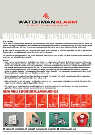
Read fully before installation and use
Check level, Pair the Fit Check
distance Drill Apply Measure Set Dip Receiver & Transmitter the
and Height Tank Base Tank Switches Transmitter to the Base level
A RECEIVER B WEATHER SEAL C SCREWS D WATCHMANALARM TRANSMITTER E WATCHMANALARM BASE
9-5405-02
2. 1. CHECK LEVEL, DISTANCE AND HEIGHT
Ensure before you start your install that the tank the WatchmanAlarm
is to be fitted to is:
1. On a flat level base (See Picture 1)
2. Within a 200-metre range of the line of sight of receiver position.
NB – Underground tanks
Please note any radio frequency signal may be seriously inhibited if
positioned underground. Please check that the transmitter - receiver
link works in the desired location before installation.
3. A maximum actual tank height of 3 metres
(tank only, not including base).
Pic 1
2. TANK PREPARATION
Alarm Transmitter
Please note- it is important to keep all items dry
during installation.
A) Pre-drilled tanks.
There may already be a 32mm pre-drilled opening in the tank top
and possibly a tube fitted. If so, remove the cover by undoing the two
screws holding it in place, and dispose of the tube in accordance with
local government guidelines.
NB – Ensure the hole is a minimum DIAMETER 30mm.
Ensure that the space beneath the WatchmanAlarm unit is free of any
obstacles and that the ultrasonic beam path is clear of obstructions.
(See Picture 2) 30cm
Pic 2
Choose a suitable
B) Un-drilled tanks. position for transmitter
Where drilling is required to fit the transmitter, choose a flat level point
that is at the same level and no higher than any opening at the top of
the tank (filling point etc.). (See Picture 3)
WARNING: If you are unsure if you should drill a tank please check
with the tank manufacturer first.
Outlet Pic 3
The Transmitter can’t sit at an angle as this gives an incorrect level
reading on the receiver. Take care not to choose an area on which
water could gather i.e. a dent/depression or a position directly above
any restricted area inside the tank. (See Picture 4)
Pic 4
NB: For tanks with window corrugations or internal braces ensure that
the WatchmanAlarm is not positioned above or within 15 cm of the Tank Braces
area of the WINDOW or the edge of the tank. If the WatchmanAlarm
is positioned over or close to the WINDOWED area it transmits faulty
readings to the receiver. (See Picture 5) Ensure that the sonic path is Tank Windows
clear to the bottom of the tank as per pic 2.
NB: When installed incorrectly on some windowed tanks the unit can
experience false alarms as the oil level drops. It is important to ensure
that the unit is positioned so that the ultrasonic beam has a 30cm
diameter clear area to the bottom of the tank. Positioning the unit too
close to the tank wall or near a tank window may cause false alarms.
Pic 5
3. Drill a hole in the place that you have selected on the tank’s top surface
using a 32mm hole-saw. (shown in Picture 6)
Warning: If you are unsure if you should drill the tank please check with 5 3 1
the tank manufacturer first.
Pic 6
3. FITTING TRANSMITTER BASE
For tanks with pre-drilled holes
• Remove cap from the hole (Picture 7) and insert
transmitter base, ensuring the weather seal is securely
in place (Picture 8 & 9).
• Tighten the WatchmanAlarm base (Part E) on to the tank
with 2 stainless steel self-tapping, counter sunkscrews
supplied (Part C). Do not over tighten!
Pic 7 Pic 8 Pic 9
4. DEFINE THE TANK HEIGHT
Accurately measure the height of your tank making note of this
measurement. The permissible maximum tank height is 3 metres
from the base of your tank to the position of the WatchmanAlarm
✓
(which should be the same
as the fill point). (Seen in Picture 10).
Pic 10
5. SETTING THE SWITCHES ON THE RECEIVER
Using the tank height chart (see section 9), read across to the relevant
multi switch settings using tank measurement you took earlier.
The multi switches are located in a recess at the back of the receiver
above the pins.
Using a screwdriver or tip of a ballpoint pen, flip the relevant switch (e.g.)
upwards (= ON).
NOTE: Switch one if set in the on (up) position will cause the unit to
bleep in the event of a low level reading. To deactivate this set the
switch to an off (down) position. Switch 1 position will not affect the
alarm function.
Switch 2 is set in the off position (down) therefore the audible notification
for the no echo condition is disabled. To enable the no echo condition
audible notification (beep 3 times every 5 seconds) put switch 2 in an
on (up) position.
Pic 11
4. 6. MATCHING RECEIVER AND TRANSMITTER 9. WATCHMANALARM RECEIVER MULTI
You should match the receiver (Part A) with the transmitter (Part C) so that SWITCH SETTING CHART
the system code is unique to your tank. You only need to do this once. Plug
receiver into a suitable and convenient electrical socket and switch on.
The display screen (Picture 12) on the front of the receiver will show a
flashing top bar as shown in diagram. This indicates that the receiver is
waiting for the unique code. The bar will continue to flash for 2 minutes
during which time you can match the transmitter to the receiver.
Hold the transmitter against the receiver right hand side, as shown
(Picture 13), so that the white dot on the transmitter is touching the
black dot on the receiver (important!) for about 20 seconds to
allow unique code to be transferred. Bars will increase up the display
screen. When all 10 bars are shown they will flash to indicate that
the unique code is transferred. When matched the transmitter must
immediately be placed on the tank.
• If you are installing more than one WatchmanAlarm unit
please wait 9 minutes between each matching.
Pic 12 Pic 13
7. FITTING THE TRANSMITTER TO THE BASE
Screw the transmitter (Part D) into the base (Part E). Ensure the
transmitter is vertical on top of the tank and level.
Ensure that the WatchmanAlarm unit is screwed correctly into the base
and that the threads have not crossed, to give a secure seal.
(See Picture 14)
Pic 14
8. CHECK THE LEVEL OF OIL IN THE TANK
The bar graph represents the level of oil in your tank.
Note: It can take up to 2 hours for the first accurate reading from
the WatchmanAlarm to be displayed.
FULL EARLY WARNING ALMOST EMPTY
YOUR WATCHMANALARM HAS NOW BEEN SUCCESSFULLY INSTALLED
5. 10. Technical information 11. GUARANTEE
The WatchmanAlarm is suitable for use in tanks for the storage of diesel The WatchmanAlarm has a warranty period of 1 year. For each product
fuel, kerosene, and gas oil types A2, C1, C2 and D as defined by BS accepted by Kingspan Environmental Ltd as warrantable, Kingspan
2869. Check with the manufacturer and/or supplier before using with Environmental will rework or replace the product and return to the
any other fluids. customer at Kingspan Environmental expense. The warranty becomes
invalid if the sealed unit is opened (Part D).
In the event of a power failure or if the receiver is switched off or moved
to a new socket: When power returns again or unit is switched on, the Kingspan Environmental Ltd will not warrant products that have been:
receiver display screen will show the top bar flashing. There is no need
to repeat the matching instruction. The top bar will continue to flash for • Used outside the functional and environmental conditions for
2 minutes, after which time the last valid signal is displayed. It may take which they were designed.
up to two hours for the next transmission from the transmitter.
• Physically abused, incorrectly handled/ installed or damaged
CHANGING BATTERY in transit.
Though the lithium battery will have a very long service life, it will • Despatched from Kingspan Environmental more than 1
eventually become exhausted and will need replacing. year previously.
Batteries can be purchased from a good photographic shop or chemist. • Returned to Kingspan Environmental in a form other than in
The battery model is: VARTA CR2430. which they were originally supplied.
• Subjects to “Act of God”, e.g.: lightning strike, flood or any
• Remove transmitter from tank other catastrophic event beyond Kingspan Environmentals control.
• Take transmitter indoors, into a clean dry environment
• Using a cross point screwdriver, undo the four screws, Any Sensor product deemed damaged by the customer shall be returned
located under the main body of transmitter to Kingspan Environmentals facility at the customer’s expense.
• Remove the top cover
• Flip out battery Kingspan Environmental shall not be liable for any costs in relation to
• Clip in new battery the returned products.
• Re-fit cover
• Evenly tighten all four screws - do not over tighten The purchase invoice and a description issue should be joined with the
• Replace transmitter on the tank faulty product. The product should be returned at your shop or directly
If the receiver detects a low battery the following warning message at the following address:
is displayed on the LCD. The level of oil in the tank plus a constantly
flashing warning triangle. (Shown in picture 15)
! ! !
LOW BATTERY 15 TRANSMISSION 16 No Echo 17
NOT HEARD CoNDITION
RECEIVER FAULT DISPLAY KEY:
If the receiver detects a transmission not heard for a long time the
symbol outlined in Pic 16 is displayed on the LCD accompanied by a
beep sequence of 3 beeps every 5 seconds (if Dip switch 2 is in the
on position). This starts approximately 12 hours from the last received
good signal. (Shown in picture 16). To rectify this re-site the receiver in
a location where the transmission is heard.
If the receiver detects a No Echo Condition the following message is
displayed on the LCD Warning triangle constantly flashing plus indication
bar 5 on. (Shown in picture 17) This is accompanied by a beep sequence
of 3 beeps every 5 seconds (if Dip switch 2 is in the on position).
To rectify this situation check that the transmitter unit is correctly
positioned on the tank and no interference is present from a tank wall,
corrugation or window.
False Alarm:
False alarms may be caused by poor installation of the unit on the
tank. Please ensure that the unit is sitting correctly on the tank with
the correct amount of clearance each side of it to the bottom of the
tank. (See section 2). Kingspan Environmental Ltd, Sensor Systems Team, 180 Gilford Road,
Portadown, Co. Armagh, Northern Ireland BT63 5LF.
Ensure that the tank is not prone to vibration by the wind or passing
traffic. Sudden ripples of the fluid in the tank caused by vibrations may
cause false alarms. Check the tank is sitting level on a stable base.
Each faulty product must receive Kingspan Environmentals
After-Sale-Service approval before being returned.