1. Role of Adder Unit
There is an Adder Unit (AU) which will generate 20-bit physical
address of the memory
i.e., actual address. It will consist base register + effective addres.
Adder unit left shift the address by 4 bits.
Physical Address(PA) = Base Address(BA) + Effective
Address(EA)
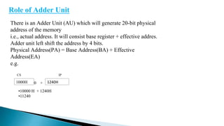
e.g.
CS IP
1000H 1240H
0 +
•10000 H + 1240H
•11240
2. Data Segment: - The effective address of data segment is given by BX, BP, SI, DI
PA = BA + (BX or BP or SI or DI)
Code Segment: - The effective address of code segment is given by IP.
PA = BA + IP
Extra Segment: - This is extra segment
Stack Segment: - The effective address of stack segment is given by SP.
PA = BA + SP
3. D15 D14 D13 D12 D11 D10 D9 D8 D7 D6 D5 D4 D3 D2 D1 D0
X X X X OF DF IF TF S Z X AC X P X CF
D15 D14 - - - - - - - D0
As it in 8085
Role of Flag Register: -
8086 has 16-bit flag register, but only 9 flags are used.
The format of flag register is like below.
OverFlow Flag (OF): - This flag works only in case of signed
number in case of unsigned number it doesn’t work.
If MSB bit 01 or 10 changes then this is called result in overflow.
Sign
Magnitude
4. Direction Flag (DF): - It will give the direction to the program if DF = 0 then it
will auto incremented and DF = 1 then it will auto decremented it can also set and reset
by using instruction. For set use Set Direction Flag (STD) for reset use Clear Direction
Flag (CLD).
Interrupt Flag (IF): - If IF = 1, then interrupts are enabled and if IF = 0, then
interrupts are disabled and it can also set or reset by using instruction for set use Set
Interrupt Flag(STI) for clear use Clear Interrupt Flag(CLI).
Trap Flag (TF): - It is used for single stepping that is it execute single instruction
at a time and display the result and so on. If TF = 1, then single stepping and TF = 0
then free running and it can also set also set or reset by instruction.