ATmega8 based password controlled home appliance
•
0 likes•361 views

It is a report on ATmega8 based password controlled home appliance, here IEEE format is maintained

Recommended
Recommended
More Related Content
What's hot
What's hot (15)
Viewers also liked
Similar to ATmega8 based password controlled home appliance
Similar to ATmega8 based password controlled home appliance (20)
Recently uploaded
Recently uploaded (20)
ATmega8 based password controlled home appliance
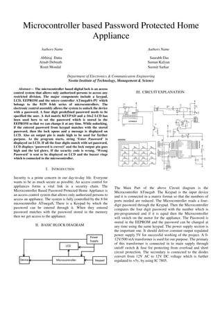
- 1. Microcontroller based Password Protected Home Appliance Authors Name Authors Name Abhiraj Datta Saurabh Das Arnab Debnath Suman Kalyan Ronit Mondal Susmit Sarkar Department of Electronics & Communication Engineering Neotia Institute of Technology, Management & Science Abstract— The microcontroller based digital lock is an access control system that allows only authorized persons to access any restricted division. The major components include a keypad, LCD, EEPROM and the micro controller ATmega8A-PU which belongs to the 8159 8-bit series of microcontrollers. The electronic control assembly allows the system to unlock the device with a password. A four digit predefined password needs to be specified the user. A 4x4 matrix KEYPAD and a 16x2 LCD has been used here to set the password which is stored in the EEPROM so that we can change it at any time. While unlocking, if the entered password from keypad matches with the stored password, then the lock opens and a message is displayed on LCD. Also an output pin is made high to be used for further purpose. As the program starts, string ‘Enter Password’ is displayed on LCD. If all the four digits match with set password, LCD displays ‘password is correct’ and the lock output pin goes high and the led glows. If the security code is wrong, ‘Wrong Password’ is sent to be displayed on LCD and the buzzer rings which is connected to the microcontroller. I. INTRODUCTION Security is a prime concern in our day-to-day life. Everyone wants to be as much secure as possible. An access control for appliances forms a vital link in a security chain. The Microcontroller Based Password Protected Home Appliance is an access control system that allows only authorized persons to access an appliance. The system is fully controlled by the 8 bit microcontroller ATmega8. There is a Keypad by which the password can be entered through it. When they entered password matches with the password stored in the memory then we get access to the appliance. II. BASIC BLOCK DIAGRAM III. CIRCUIT EXPLANATION The Main Part of the above Circuit diagram is the Microcontroller ATmega8. The Keypad is the input device and it is connected in a matrix format so that the numbers of ports needed are reduced. The Microcontroller reads a four- digit password through the Keypad. Then the Microcontroller compares the four digit password with the number which is pre-programmed and if it is equal then the Microcontroller will switch on the motor for the appliance. The Password is stored in the EEPROM and the password can be changed at any time using the same keypad. The power supply section is the important one. It should deliver constant output regulated power supply 5V for successful working of the project. A 0- 12V/500 mA transformer is used for our purpose. The primary of this transformer is connected in to main supply through on/off switch & fuse for protecting from overload and short circuit protection. The secondary is connected to the diodes convert from 12V AC to 12V DC voltage which is further regulated to +5v, by using IC 7805.
- 2. IV. HARDWARE DESIGN Microcontroller ATmega8A-PU LCD Display Relay Interface Buzzer A. Microcontroller ATmega8A-PU High-performance, Low-power consumption with Advanced RISC Architecture. High Endurance Non-volatile Memory segments. a. 8KBytes of In-System Self-programmable Flash program memory. b.512Bytes EEPROM. c. 1KByte Internal SRAM. Operating Voltages a. 2.7 - 5.5V b. 0 - 16MHz Power Consumption at 4MHz, 3V, 25°C a. Active: 3.6mA b.Idle Mode: 1.0mA c. Power-down Mode: 0.5μA. Internal Calibrated RC Oscillator. B. LCD display The dot-matrix liquid crystal display controller and driver LSI displays alphanumeric, characters, and symbols. It can be configured to drive a dot-matrix liquid crystal display under the control of a 4 or 8-bit microprocessor. Since all the functions such as display RAM, character generator, and liquid crystal driver, required for driving a dot-matrix liquid crystal display are internally provided on one chip, a minimal system can be interfaced with this controller/driver. A single HD44780U can display up to two 8-character lines (16 x 2).A 16 x 2 line LCD module to display user information. Micro controller send the data signals through pin 11 through 18(RC0-RC3) and control signal through 4,6 and 7 of the micro controller. Pin no 3 of the LCD is used to control the contrast by using preset PR1. C. Relay Interface A single pole dabble throw (SPDT) relay is connected to port RB1 of the microcontroller through a driver transistor. The relay requires 12 volts at a current of around 100ma, which cannot provide by the micro- controller. So the driver transistor is added. The relay is used to operate the external solenoid forming part of a locking device or for operating any other electrical devices. Normally the relay remains off. As soon as pin of the microcontroller goes high, the relay operates. When the relay operates and releases. Diode D2 is the standard diode on a mechanical relay to prevent back EMF from damaging Q3 when the relay releases. LED L2 indicates relay on. D. Buzzer A buzzer connected to port RB0 of the micro controller through a driver transistor. The buzzer requires 12 volts at a current of around 50ma, which cannot provided by the micro controller. So the driver transistor is added. The buzzer is used to audible indication for valid user and error situation and alarm mode. As soon as pin of the micro controller goes high, the buzzer operates.
- 3. E. Keypad Interfacing At the lowest level, keyboards are organized in a matrix of rows and columns. The microcontroller accesses both rows and column through ports; therefore, with two 8-bit ports, an 4*3 matrix of keys can be connected to a microprocessor. When a key pressed, a row and column make a connect; otherwise, there is no connection between row and column. In our project the function of programs stored in the EEPROM of microcontroller to scan the keys continuously, identify which one has been activated, and present it to the microcontroller. In this section we look at the mechanism by which the ATmega8 scans and identifies the key. V. Abbreviations and Acronyms: EEPROM-Electrically Erasable Programmable Read Only Memory. LCD- Liquid Crystal Display. RISC- Reduced instruction set computing. LED- Light Emitting Diode. SRAM- Static Random Access Memory. VI. Acknowledgment We are using this opportunity to express our gratitude to everyone who supported us throughout the course of this B.Tech final year project. We are thankful for their aspiring guidance, invaluably constructive criticism and friendly advice during the project work. We are sincerely grateful to them for sharing their truthful and illuminating views on a number of issues related to the project. We express our warm thanks to our project mentors Prof. Biplob Roy and Prof. Amrita Saha for their support and guidance at NITMAS. VII. REFERENCES 1) Programming in ANSI C: E Balaguruswamy. 2) The 8051microcontroller & embedded systems: Muhammad Ali Mazidi and Janice Gillispie Mazidi. 3) www.atmel.com 4) www.scientech.bz