SlideShare una empresa de Scribd logo
1 de 19
7. Options
Chapter 7 Options
7-1 Outline of options
The VAT300 Series options include those shown below. This chapter will focus on the stand-alone
options and main circuit wiring devices.
Fig. 7-1 Option configurations
Table 7-1-a
Item Type Function
Main circuit wiring devices
Circuit
Breaker
(MCCB) or
fuse
(Refer to Table 7-1-b.)
Refer to Chapter 9
when using a UL/cUL
compliant product.
Always install this device to protect the wiring of the inverter
and peripheral devices.
Magnetic
contactor
(MC)
Select a device for the
inverter rating.
(Refer to Table 7-1-b.)
Install this device to provide an operation interlock.
When using the DB unit, always install this device to protect
the DBR. (Refer to Fig. 2-3-a.)
Stand-alone options
ACL ACR-
(Refer to Table 7-1-b.)
Always install the AC reactor (ACL) in the following cases.
- For N045K0/X055K0 or lower capacities (heavy duty)
When the capacity of the power supply transformer exceeds
500kVA
- For X075K0 or higher capacities (heavy duty)
When the capacity of the power supply transformer exceeds
10 times the inverter capacity.
This is also effective in improving the power factor of the
inverter input, in suppressing the current high harmonics and
extending the life of the main circuit's electrolytic capacitor.
The power factor will be approx. 0.9.
DCL DCR-
(Refer to Table 7-1-b.)
Same as ACL, DC reactor (DCL) is effective in improving
the power factor of the inverter input, in suppressing the
current high harmonics and extending the life of the main
circuit's electrolytic capacitor. The power factor will be
approx. 0.9.
EMI filter 3SUP-
(Refer to Table 7-1-b.)
This device suppresses the electromagnetic noise generated
by the inverter.
Mounting of this device is recommended for creating a
balance with the peripheral devices of the inverter.
DB unit U2KV23DBU-
(Refer to Table 7-1-b.)
This is used when the motor is to be stopped with dynamic
braking.
Surge
Absorber
ACFRxxx + RC filter This suppress surge voltage at motor side, which may be
generated, if length of output motor cable exceeds of 50mts
7 – 1
D C L
D B R U n it
V A T 3 0 0
M C A C L
E x te r n a l
N o is e F ilt e r
S u r g e a b s o r b e rM C C B o r
fu s e
P o w e r S u p p ly
M a in c ir c u it w ir in g d e v ic e
S ta n d - A lo n e o p tio n
B u ilt- in P C B o p tio n
M
3 p h
B u ilt- in E M C filte r o p tio n
7. Options
Table 7-1-a (continued)
Built-in PCB options (These are built-in type options mounted on the basic PCB of the inverter.)
Item
Type
(Instruction
manual)
Function Class
Indication
of rating
nameplate
(Note 1)
Speed detection 1
(complimentary type
compatible)
U30V24DN1
N62P30609=1-01
(PCST-3480)
This is a speed detection PCB for the complimentary output
type encoder.
Response frequency: Change between 60±10kHz and
20kHz.
I 1
Speed detection 2
(line driver
compatible)
U30V24DN2
N62P30610=1-01
(PCST-3481)
This is a speed detection PCB for the line driver output type
encoder.
Response frequency: 250kHz (signal: A, B, Z, S phase)
I 2
Speed detection 3
(PM compatible)
U30V24DN3
N62P30611=1-01
(PCST-3482)
This is a speed (pole position) detection PCB for the PM drive
control, and is compatible with the line driver output type
encoder.
Response frequency: 250kHz (signal: A, B, Z, U, V, W
phase)
I 3
Speed detection 4
(Note 2)
U30V24DN4
N62P30642=1-01
(PCST-3483)
Speed detection PCB compatible with Heidenhain ERN1387.
1Vp-p 2-phase, 2-set sine wave + Z-phase pulse I 4
Speed detection 6 U30V24DN6
N62P30609=2-01
(PCST-3480)
This is a speed detection PCB for the single-phase
complementary output type encoder circuit. The signal high level
is set to 4V or more, and the low level is set to 1.0V or less.
I 6
Relay interface U30V24RY0
N62P30612=1-01
(PCST-3477)
This is used to expand the contact input/output points.
Relay input : 4 points (PSI8 to 11)
1c contact output : 4 points (PSO4 to 7)
III N
Parallel interface U30V24PI0
N62P30614=1-01
(PCST-3475)
This is used to receive parallel settings from the PLC.
Parallel data input : 16 bits
Data length : 16, 12, 8 bits selective
Format : Binary or BCD selective
Open collector output : 2 points (PSO4, 5)
III M
Insulated AI/AO
(Note 2)
U30V24AI0
N62P30622=1-01
(PCST-3479)
An insulated 4ch analog input, analog output is possible.
Analog input : 16 bits (input range ±10V)
Analog output : 12 bits (output range 10V)
II S
Profibus-DP
interface
U30V24SL0
N62P30616=1-01
(PCST-3466)
This is used to make a connection with the network on the
Profibus-DP communication protocol.
Transmission speed : 12Mbps
No. of stations : 126 stations in one network
III H
CC-Link interface U30V24SL3
N62P30619=1-01
(PCST-3472)
This is used to make a connection with the CC-Link network.
Transmission speed : 156kbps, 625kbps, 2.5Mbps, 5Mbps,
10Mbps
(DIP switch settings can be made.)
No. of stations : 64 stations in one network
III K
DeviceNet interface U30V24SL2
N62P30618=1-01
(PCST-3470)
This is used to make a connection with the DeviceNet network.
Transmission speed : 125kbps, 250kbps, 500kbps
(DIP switch settings can be made.)
No. of stations : 64 stations in one network
III J
CANopen interface U30V24SL1
N62P30617=1-01
(PCST-3468)
This is used to make a connection with the CANopen network.
Transmission speed : 125kbps, 250kbps, 500kbps, 1Mbps
(DIP switch settings can be made.)
No. of stations : 128 stations in one network
III I
(Note 1) "0" indicates that the optional PCB is not installed.
(Note 2) The speed detection 4 (U30V24DN4) and insulated AI/AO (U30V24AIO) cannot be used simultaneously.
7 – 2
7. Options
Table 7-1-b Main circuit wiring device ratings, and stand-alone option preparation
drawing numbers and types (Normal-duty)
VAT300 Motor MCCB Line EMC Dynamic Braking DBR INPUT DC Surge Absorber (5)
Type KW(1) (2) (A) MC Filter (3) Module (Note 4) AC Reactor Reactor Reactor + RC
N000K7 0.75 15 CL00 Built in Built in DB TLR216P200 ACRP6A2H5 - -
N001K5 1.5 15 CL00 Built in Built in DB TLR108P200 ACRP9A1H3 - -
N002K2 2.2 15 CL00 Built in Built in DB TLR74P200 ACRP12A0H84 - -
N004K0 4 20 CL01 Built in Built in DB TLR44P600 ACRP18A0H56 - -
N005K5 5.5 30 CL02 Built in Built in DB TLR29P600 ACRP27A0H37 - -
N007K5 7.5 40 CL04 U30F3075EB Built in DB TLR22P600 ACRP35A0H27 DCRP45A0H55 -
N011K0 11 60 CL04 U30F3075EB Built in DB TLR15P1000 ACRP55A0H18 DCRP60A0H4 -
N015K0 15 80 CL06 U30F3100EB Built in DB TLR11P1200 ACRP70A0H14 DCRP80A0H3 -
N018K5 18.5 100 CL07 U30F3100EB Built in DB TLR8,8P1500 ACRP80A0H14 DCRP100A0H24 -
N022K0 22 125 CL09 U30F3130EB U2KV23DBUL2 TLR7,4P1800 ACRP97A0H11 DCRP120A0H2 -
N030K0 30 150 CL10 U30F3180EB U2KV23DBUL3 TLR5P2500 ACRP140A0H072 DCRP150A0H17 -
N037K0 37 200 CK75 U30F3250ES U2KV23DBUL3 TLR4P3000 ACRP180A0H056 DCRP180A0H14 -
N045K0 45 225 CK75 U30F3250ES U2KV23DBUL4 - ACRP200A0H051 DCRP220A0H11 -
X000K7 0.75 15 CL00 Built in Built in DB TLR864P200 ACRP3A8H1 - ACFRP10A + RC
X001K5 1.5 15 CL00 Built in Built in DB TLR432P200 ACRP4A5H1 - ACFRP10A + RC
X002K2 2.2 15 CL00 Built in Built in DB TLR295P200 ACRP6A3H4 - ACFRP10A + RC
X004K0 4 15 CL00 Built in Built in DB TLR175P600 ACRP10A2H - ACFRP10A + RC
X005K5 5.5 20 CL00 Built in Built in DB TLR118P600 ACRP14A1H4 - ACFRP14A + RC
X007K5 7.5 25 CL02 Built in Built in DB TLR86P600 ACRP18A1H1 DCRP25A2H1 ACFRP18A + RC
X011K0 11 30 CL04 Built in Built in DB TLR59P1000 ACRP27A0H75 DCRP32A1H6 ACFRP27A + RC
X015K0 15 40 CL04 Built in Built in DB TLR43P1000 ACRP35A0H58 DCRP40A1H2 ACFRP35A + RC
X018K5 18.5 50 CL04 Built in Built in DB TLR35P1500 ACRP38A0H58 DCRP50A0H96 ACFRP38A + RC
X022K0 22 60 CL06 Built in Built in DB TLR29P1800 ACRP45A0H45 DCRP60A0H82 ACFRP45A + RC
X030K0 30 80 CL06 Built in U2KV23DBUH3 TLR22P2500 ACRP70A0H29 DCRP80A0H58 ACFRP62A + RC
X037K0 37 100 CL07 U30F3100EB U2KV23DBUH3 TLR18P3000 ACRP90A0H22 DCRP100A0H49 ACFRP90A + RC
X045K0 45 125 CL09 U30F3130EB U2KV23DBUH4 TLR15P3700 ACRP90A0H22 DCRP125A0H40 ACFRP90A + RC
X055K0 55 150 CL09 U30F3180EB U2KV23DBUH4 - ACRP115A0H18 DCRP140A0H32 ACFRP115A + RC
X075K0 75 200 CK75 U30F3250ES U2KV23DBUH4 - ACRP160A0H14 DCRP180A0H25 ACFRP160A + RC
X090K0 90 225 CK08 U30F3250ES U2KV23DBUH4 - ACRP185A0H11 DCRP210A0H25 ACFRP185A + RC
X110K0 110 300 CK85 U30F3320ES U2KV23DBUH4 - ACRP225A0H096 DCRP270A0H18 ACFRP300A + RC
X132K0 132 350 CK09 U30F3400ES U2KV23DBUH4 - ACRP300A0H067 DCRP310A0H14 ACFRP300A + RC
X160K0 160 400 CK09 U30F3600ES U2KV23DBUH4 - ACRP360A0H056 DCRP400A0H13 ACFRP360A + RC
X200K0 200 500 CK95 U30F3600ES U2KV23DBUH4 - ACRP460A0H056 DCRP540A0H08 ACFRP460A + RC
X250K0 250 600 CK10 U30F31000ES 2xU2KV23DBUH4 - ACRP550A0H039 DCRP650A0H07 ACFRP550A + RC
X315K0 315 800 CK11 U30F31000ES 2xU2KV23DBUH4 - ACRP700A0H035 DCRP740A0H06 ACFRP700A + RC
X400K0 400 1000 CK12 U30F31000ES 2xU2KV23DBUH4 - ACRP850A0H023 DCRP950A0H05 ACFRP850A + RC
X475K0 475 1200 U30F31600ES 3xU2KV23DBUH4 - ACRP950A0H016 DCRP1000A0H04 ACFRP950A + RC
(Note 1) Device selection conditions, for Normal Duty (Overload capacity 120%, 60s)
• The input current is calculated as follows: I = (IMkW)/ηIM/ηINV/COSø/voltage/√    3
• The ηIM (motor efficiency) is 0.85 for 11kW or less, 0.9 for 15kW or more.
• The ηINV (inverter efficiency) is 0.95.
• COSø is 0.5 to 0.6 at the input power factor. When using ACL or DCL, recalculate as 0.9.
• The power supply voltage is 200V/380V. (If the power supply voltage differs, recalculate and select.)
(Note 2) Fuses or MCCB given are for IEC Ratings
When complying with UL/cUL, use a UL certified fuse as indicated in section 9-1.
(Note 3) Built-in EMC filters only in specified ratings and for drives U3SN_____F__ or U3SX_____F__
(Note 4) External Dynamic Braking Resistors for optimal performance. Note drives up to U3SN011K0 and U3SX11K0
include a built in DBR, which should be disconnected when using the external DBR
Check 7-3-1 section.
(Note 5) The Surge absorber -useful when length of motor cable is more than 50mts- is configured using the output
reactor shown in above table plus RC filter, N11P34018=7 (use up to 1kHz carrier frequency)
7 – 3
7. Options
Table 7-1-b Main circuit wiring device ratings, and stand-alone option preparation
drawing numbers and types (Heavy-duty)
VAT300 Motor MCCB Line EMC Dynamic Braking DBR INPUT DC Surge Absorber (5)
Type KW (1) (2) (A) MC Filter (3) Module (Note 4) AC Reactor Reactor Reactor + RC
N000K7 0.4 15 CL00 Built in Built in TLR405P200 ACRP4A2H5 - -
N001K5 0.75 15 CL00 Built in Built in TLR216P200 ACRP6A2H5 - -
N002K2 1.5 15 CL00 Built in Built in TLR108P200 ACRP9A1H3 - -
N004K0 2.2 20 CL00 Built in Built in TLR74P200 ACRP12A0H84 - -
N005K5 4 30 CL01 Built in Built in TLR44P600 ACRP18A0H56 - -
N007K5 5.5 35 CL02 U30F3075EB Built in TLR29P600 ACRP27A0H37 DCRP32A0H78 -
N011K0 7.5 50 CL04 U30F3075EB Built in TLR22P600 ACRP35A0H27 DCRP45A0H55 -
N015K0 11 70 CL04 U30F3100EB Built in TLR15P1000 ACRP55A0H18 DCRP60A0H4 -
N018K5 15 90 CL06 U30F3100EB Built in TLR11P1200 ACRP70A0H14 DCRP80A0H3 -
N022K0 18.5 125 CL07 U30F3130EB U2KV23DBUL2 TLR8,8P1500 ACRP80A0H14 DCRP100A0H24 -
N030K0 22 125 CL09 U30F3180EB U2KV23DBUL2 TLR7,4P1800 ACRP97A0H11 DCRP120A0H2 -
N037K0 30 150 CL10 U30F3250ES U2KV23DBUL3 TLR5P2500 ACRP140A0H072 DCRP150A0H17 -
N045K0 37 200 CK75 U30F3250ES U2KV23DBUL3 TLR4P3000 ACRP180A0H056 DCRP180A0H14 -
X000K7 0.4 15 CL00 Built in Built in TLR864P200 ACRP3A8H1 - ACFRP10A + RC
X001K5 0.75 15 CL00 Built in Built in TLR864P200 ACRP3A8H1 - ACFRP10A + RC
X002K2 1.5 15 CL00 Built in Built in TLR432P200 ACRP4A5H1 - ACFRP10A + RC
X004K0 2.2 15 CL00 Built in Built in TLR295P200 ACRP6A3H4 - ACFRP10A + RC
X005K5 4 15 CL00 Built in Built in TLR175P600 ACRP10A2H - ACFRP10A + RC
X007K5 5.5 20 CL00 Built in Built in TLR118P600 ACRP14A1H4 DCRP18A2H9 ACFRP14A + RC
X011K0 7.5 25 CL02 Built in Built in TLR86P600 ACRP18A1H1 DCRP25A2H1 ACFRP18A + RC
X015K0 11 35 CL04 Built in Built in TLR59P1000 ACRP27A0H75 DCRP32A1H6 ACFRP27A + RC
X018K5 15 50 CL04 Built in Built in TLR43P1000 ACRP35A0H58 DCRP40A1H2 ACFRP35A + RC
X022K0 18.5 60 CL04 Built in Built in TLR35P1500 ACRP38A0H58 DCRP50A0H96 ACFRP38A + RC
X030K0 22 70 CL06 Built in U2KV23DBUH2 TLR29P1800 ACRP45A0H45 DCRP60A0H82 ACFRP45A + RC
X037K0 30 80 CL06 U30F3100EB U2KV23DBUH3 TLR22P2500 ACRP70A0H29 DCRP80A0H58 ACFRP62A + RC
X045K0 37 100 CL07 U30F3130EB U2KV23DBUH3 TLR18P3000 ACRP90A0H22 DCRP100A0H49 ACFRP90A + RC
X055K0 45 125 CL09 U30F3180EB U2KV23DBUH4 TLR15P3700 ACRP115A0H18 DCRP125A0H40 ACFRP115A + RC
X075K0 55 150 CK75 U30F3180EB U2KV23DBUH4 - ACRP115A0H18 DCRP140A0H32 ACFRP115A + RC
X090K0 75 200 CK08 U30F3250ES U2KV23DBUH4 - ACRP160A0H14 DCRP180A0H25 ACFRP160A + RC
X110K0 90 225 CK85 U30F3250ES U2KV23DBUH4 - ACRP185A0H11 DCRP210A0H25 ACFRP185A + RC
X132K0 110 300 CK09 U30F3320ES U2KV23DBUH4 - ACRP225A0H096 DCRP270A0H18 ACFRP225A + RC
X160K0 132 350 CK09 U30F3400ES U2KV23DBUH4 - ACRP300A0H067 DCRP310A0H14 ACFRP300A + RC
X200K0 160 400 CK95 U30F3600ES U2KV23DBUH4 - ACRP360A0H056 DCRP400A0H13 ACFRP360A + RC
X250K0 200 500 CK10 U30F3600ES U2KV23DBUH4 - ACRP460A0H056 DCRP540A0H08 ACFRP460A + RC
X315K0 250 700 CK11 U30F31000ES 2xU2KV23DBUH4 - ACRP550A0H039 DCRP650A0H07 ACFRP550A + RC
X400K0 315 800 CK12 U30F31000ES 2xU2KV23DBUH4 - ACRP700A0H035 DCRP740A0H06 ACFRP700A + RC
X475K0 400 1000 U30F31000ES 2xU2KV23DBUH4 ACRP850A0H023 DCRP950A0H05 ACFRP850A + RC
(Note 1) Device selection conditions for Heavy Duty (Overload capacity 150%, 60s)
• The input current is calculated as follows: I = (IMkW)/ηIM/ηINV/COSø/voltage/√    3
• The ηIM (motor efficiency) is 0.85 for 11kW or less, 0.9 for 15kW or more.
• The ηINV (inverter efficiency) is 0.95.
• COSø is 0.5 to 0.6 at the input power factor. When using ACL or DCL, recalculate as 0.9.
• The power supply voltage is 200V/380V. (If the power supply voltage differs, recalculate and select.)
(Note 2) Fuses or MCCB given are for IEC Ratings
When complying with UL/cUL, use a UL certified fuse as indicated in section 9-1.
(Note 3) Built-in EMC filters only in specified ratings and for drives U3SN_____F__ or U3SX_____F__
(Note 4) External Dynamic Braking Resistors for optimal performance. Note drives up to U3SN011K0 and
U3SX015K0 include a built in DBR, which should be disconnected when using the external DBR
Check 7-3-1 section.
(Note 5) The Surge absorber -useful when length of motor cable is more than 50mts- is configured using the output
reactor shown in above table plus RC filter, N11P34018=7 (use up to 1kHz carrier frequency)
7 – 4
7. Options
7-2 Built-in PCB option
This is a built-in type option mounted on the VAT300 control PCB.
One type can be selected from option I, option II and option III. Up to three types of PCB options can be
mounted at once.
These PCB options are connected to the connector on the VAT300 control PCB, and can be easily
mounted even after purchasing the VAT300.
Refer to each instruction manual for details on the PCB options.
* A dedicated PCB mounting jig is required when mounting the PCB option II and III at the same time.
7-2-1 Option classes
(1) Option I
This is the PCB option for speed detection 1 to 4. The mounting position I is fixed.
(2) Option II
This is the PCB option for the Insulated AI/AO interface, etc. The mounting position is position II.
(3) Option III
This is the PCB option for the relay interface, serial communication etc. The mounting position is
position III.
(Position III is PCB mounted on the PCB option at position II.)
Refer to Table 7-1-a for the detailed option classes.
Built-in PCB option mounting drawing
7 – 5
Control PCB cover
Option I
Option III
Option II
(position
II)
(position III)
i )
(position I)
i )
7. Options
Notes for moving Operation panel folder
Do not raise the operation panel folder with an angle of
larger than 90°, so that the folder should not be fallen off.
If the operation panel folder should be taken off, push
the hinges of the folder lightly and insert them into the
original positions.
7 – 6
Fig. 7-2-1-c
Fig. 7-2-1-b
7. Options
7-3 Dynamic braking (DB) option
The VAT300 has a dynamic braking option.
Note) When Unit built-in DBR is used, set the DBR overload protection parameter (C22-4) to less than
the actual used %ED (Max. 10.0). When the external DB unit is used, set C22-4 to 0.0.
7-3-1 Built-in DB circuit N018K0 / X022K0 and smaller
The DB transistor is built in as a standard for the N018K0 / X022K0 and smaller capacities.
For the N011K0/X015K0 and smaller capacities, the DB resistor (DBR) can be built in as an option.
When using the DB, use at 10%ED or less as shown in Fig. 7-3-1-a.
When using the dynamic braking option, set the Regenerative current limit (B18-1) and the DB option
selection (C31-0 f0 ).
T
t2t1
Speed
Fig. 7-3-1-a
(1) Unit built-in DBR
The specification of DBR built into the unit is shown in Table 7-3-1-a. If these resistors are applied,
use within t(sec) shown in Table 7-3-1-a.
Table 7-3-1-a Unit built-in DBR
Inverter
type
VAT300
U3S_
Resistance
capacity
(W)
Built-in
DBR
(Ω)
Heavy-duty Normal-duty
t
(sec)
(Note 1)
Motor
capacity
(kW)
Braking
torque
(%)
Motor
capacity
(kW)
Braking
torque
(%)
N000K7 120 220 0.4 200 0.75 110 30
N001K5 120 220 0.75 110 1.5 55 30
N002K2 120 220 1.5 55 2.2 35 30
N004K0 120 180 2.2 45 4.0 25 20
N005K5 120 110 4.0 40 5.5 30 10
N007K5 120 91 5.5 35 7.5 25 10
N011K0 120 91 7.5 25 11 15 10
X000K7 120 430 0.4 340 0.75 220 10
X001K5 120 430 0.75 220 1.5 130 10
X002K2 120 430 1.5 130 2.2 75 10
X004K0 120 430 2.2 75 4.0 40 10
X005K5 120 430 4.0 40 5.5 30 10
X007K5 120 430 5.5 30 7.5 20 10
X011K0 120 430 7.5 20 11 15 10
X015K0 120 430 11 15 15 10 10
(Note 1) Set C22-4 to [t / 600sec] × 100%.
7 – 7
(position I)
i )
7. Options
(2) External DB resistor
If the braking torque is insufficient with the above built-in resistor, provide an external DB resistor
with a circuit as shown in Fig. 7-3-1-b. When using an external DB resistor, remove the built-in DB
resistor. The resistance value and usable minimum resistance value to obtain a 100% braking
torque is shown in Table 7-3-1-b.
When using the external DB resistor, use of a burning prevention circuit, including the thermal relay
(76D) shown in Fig. 7-3-1-b. is recommended.
DBR Transistor
External DB resistor
2L+1
MC
ON
OFF
MC
76D
THRY
MC control
sequence circuit
Fig. 7-3-1-b DBR circuit
Table 7-3-1-b External DBR
Inverter type
VAT300 U3S_
Heavy-duty Normal-duty
Motor
capacity
(kW)
100% braking
resistance type
Motor
capacity
(kW)
100% braking
resistance type
N000K7 0.4 TLR405P200 0.75 TLR216P200
N001K5 0.75 TLR216P200 1.5 TLR108P200
N002K2 1.5 TLR108P200 2.2 TLR74P200
N004K0 2.2 TLR74P200 3.7 TLR44P600
N005K5 4.0 TLR44P600 5.5 TLR29P600
N007K5 5.5 TLR29P600 7.5 TLR22P600
N011K0 7.5 TLR22P600 11 TLR15P1000
N015K0 11 TLR15P1000 15 TLR11P1200
N018K5 15 TLR11P1200 18 TLR8,8P1500
X000K7 0.4 TLR864P200 0.75 TLR864P200
X001K5 0.75 TLR864P200 1.5 TLR432P200
X002K2 1.5 TLR432P200 2.2 TLR295P200
X004K0 2.2 TLR295P200 3.7 TLR175P600
X005K5 4.0 TLR175P600 5.5 TLR118P600
X007K5 5.5 TLR118P600 7.5 TLR86P600
X011K0 7.5 TLR86P600 11 TLR59P1000
X015K0 11 TLR59P1000 15 TLR43P1000
X018K5 15 TLR43P1000 18 TLR35P1500
X022K0 18 TLR35P1500 22 TLR29P1800
7 – 8
7. Options
Table 7-3-1-c External DBR Dimensions
Resistance Wire Dimensions
(Note1) (mm2
) A B C D E G Type
TLR405P200 2.5 215 80 235 40 ∅ - - 1(*)
TLR216P200 2.5 215 80 235 40 ∅ - - 1(*)
TLR108P200 2.5 215 80 235 40 ∅ - - 1(*)
TLR74P200 2.5 215 80 235 40 ∅ - - 1(*)
TLR44P600 2.5 430 95 460 57 - - 1
TLR29P600 2.5 430 95 460 57 - - 1
TLR22P600 2.5 430 95 460 57 - - 1
TLR15P1000 2.5 430 105 460 66 - - 1
TLR11P1200 4 430 125 460 80 - - 1
TLR864P200 2.5 215 80 235 40 ∅ - - 1(*)
TLR432P200 2.5 215 80 235 40 ∅ - - 1(*)
TLR295P200 2.5 215 80 235 40 ∅ - - 1(*)
TLR175P600 2.5 430 95 460 57 - - 1
TLR118P600 2.5 430 95 460 57 - - 1
TLR86P600 2.5 430 95 460 57 - - 1
TLR59P1000 2.5 430 105 460 66 - - 1
TLR43P1000 2.5 430 105 460 66 - - 1
TLR35P1500 2.5 430 105 460 139 105 65 2
Note 1 Recommended resistor is rated for a ED of
10%, with maximum braking time of 20 sec.
For braking large inertia loads, ask your
supplier for an appropriate resistor.
Note that VAT300 up to N011K5 and up to
X015K5, include DB resistor as shown in table 7-
3-1a. This should be disconnected when using
external resistors
Type 1(*) As type 1, but provided with 210mm output
cable (No terminals)
7 – 9
D
B B
T y p e 1
T y p e 2
A
C
D
B B
A
C
G
E
7. Options
7-3-2 External DB unit N022K0 / X030K0 and higher
Use an external DB unit when carrying out dynamic braking with the N022K0/X030K0 and larger
unit.
Applicable DB unit, the resistance value and usable minimum resistance value to obtain a 100%
braking torque, is shown in Table 7-3-2.
Connect the DB unit as shown in Fig. 7-3-2. When carrying out dynamic braking with one DB unit,
use at 10%ED or less as shown in Fig. 7-3-1-a. If the braking torque is insufficient with one unit,
connect a DB unit in parallel.
Set in module U2KV23DBU the parameters A0.x and A1.x at least. Check manual of U2KV23DBU.
L-
M
L1
L2
L3
B
L+L-L+
MC
L+1 L+2 L-
MC
76D
THRY
VAT300
B
又は
U
V
W
MC
MC ON
OFF
DB unit No. 1
(V23DBU-)
DB unit No. 2
(V23DBU-)MC control
sequence circuit
DB
resistor
DB resistor
DB unit
Fault
Fig. 7-3-2 DB unit connection
Table 7-3-2 External DB unit
Inverter
type
VAT300
U3S_
Heavy-duty Normal-duty
Moto
r
(kW)
DB u n i t t y p e
U2KV23_
100% braking
resistance (3)
Motor
(kW)
DB u n i t t y p e
U2 KV23_
100% braking
resistance (3)
N022K0 18
DBUL2
TLR8,8P1500 22 DBUL2 TLR7,4P1800
N030K0 22 TLR7,4P1800 30
DBUL3
TLR5P2500
N037K0 30
DBUL3
TLR5P2500 37 TLR4P3000
N045K0 37 TLR4P3000 45 DBUL4 (4) 3.8Ω
X030K0 22 DBUH2 TLR29P1800 30
DBUH3
TLR22P2500
X037K0 30
DBUH3
TLR22P2500 37 TLR18P3000
X045K0 37 TLR18P3000 45
DBUH4
TLR15P3700
X055K0 45
DBUH4
TLR15P3700 55 (4) 12.5Ω
X075K0 55 (4) 12.5Ω 75 (4) 9.2Ω
X090K0 75 (4) 9.2Ω 90 (4) 7.7Ω
X110K0 90 (4) 7.7Ω 110 (4) 6.3Ω
X132K0 110 (4) 6.3Ω 132 (4) 5.2Ω
X160K0 132 (4) 5.2Ω 160 (4) 4.3Ω
X200K0 160 (4) 4.3Ω 200 (4) 3.4Ω
X250K0 200 (4) 3.4Ω 250
DBUH4 × 2 units
(4) 5.6Ω × 2 sets
X315K0 250
DBUH4 × 2 units
(4) 5.6Ω × 2
sets
315 (4) 4.4Ω × 2 sets
X400K0 315
(4) 4.4Ω × 2
sets
400 (4) 3.4Ω × 2 sets
X475K0 400
(4) 3.4Ω × 2
sets
475 DBUH4 × 3 units (4) 4.5Ω × 3 sets
7 – 10
7. Options
7 – 11
7. Options
(1) Set the following parameters when using external DB unit.
C31-0 f1 = 2 : With DB
B18-1 = 100% : Regenerative current limit
B22-5 = 100% : Regenerative current limit (Auxiliary drive0)
B26-5 = 100% : Regenerative current limit (Auxiliary drive1)
B2A-5 = 100% : Regenerative current limit (Auxiliary drive2)
B2E-5 = 100% : Regenerative current limit (Auxiliary drive3)
(2) Obtain the power generation capacity and DBR resistance value with the following expressions.
Power generation capacity (kW) =
Regenerative torque
Motor rated torque
× 0.85× Motor capacity (kW)
DBR resistance value =
K
Power generation capacity
Note that for the 200V Series, K = 148.2
For the 400V Series, K = 593
(3) GE standard resistors TLRxxx are given for drives up to X055K0, and 5%ED. Ask your dealer for
bigger ratings or heavier duty usage
(4) Braking resistors for ratings above X055K0 are are only available by special request to GE. Resistance
value is shown in ohms. Ask your dealer for details
3.2-3 Dimensions of external Dynamic Braking Resistors and Braking Units
(1) External Resistors
(2) External Braking Units
7 – 12
Resistance Wire Dimensions
(Note1) (mm2
) A B C D E G Type
TLR8,8P1500 4 430 105 460 139 105 65 2
TLR7,4P1800 6 430 105 460 139 105 65 2
TLR5P2500 16 430 105 460 207 185 136 2
TLR4P3000 16 410 180 430 139 119 68 2
TLR29P1800 4 430 105 460 139 105 65 2
TLR22P2500 6 430 105 460 207 185 136 2
TLR18P3000 16 410 180 430 139 119 68 2
TLR15P3700 16 410 180 430 139 119 68 2
D
B B
T y p e 1
T y p e 2
A
C
D
B B
A
C
G
E
7. Options
1 3 1
8 02 5 .5 2 5 .5
1 3 3
1 2 9
186
198
66
6
1 4 5
1 0 81 8 . 5
2 0 9
2 0 5
180
198
99
6
1 8 .5
U2KV23DBUL1, L2, L3 U2KV23DBUH4
U2KV23DBUH1, H2, H3
7-4 AC Reactors, DC Reactors and Surge absorbers
Select the ACL and DCL according to the Table 7-1-b inverter type. Refer to Table 7-4-a, Table 7-4-b
and Table 7-4-c for the outline dimension. The ACL is equivalent to a 3% impedance of the inverter
capacity.
Table 7-4-a Outline dimensions of ACL
DIMENSIONS (mm) Weight Losses
Catalolg # Drawing A B C D E Ø (kg) W
ACRP4A2H5 1 120 80 152 41 100 6 1,3 16
ACRP6A2H5 1 120 80 152 41 100 6 1,5 18
ACRP9A1H3 1 120 80 152 41 100 6 1,6 17
ACRP12A0H84 1 120 80 152 41 100 6 1,7 18
ACRP18A0H56 1 120 90 152 51 100 6 2,4 21
ACRP27A0H37 1 150 95 183 46 125 6 3,3 32
ACRP35A0H27 1 150 95 183 46 125 6 3,7 35
ACRP55A0H18 1 150 110 183 61 125 6 5,5 42
ACRP70A0H14 1 150 111 250 77 100 9 5,6 100
ACRP80A0H14 1 150 121 250 87 100 9 7,1 108
ACRP97A0H11 1 150 126 250 92 100 9 7,8 124
ACRP140A0H072 3 180 166 216 92 120 9 11,9 155
ACRP180A0H056 3 180 176 216 102 120 9 14,2 175
ACRP200A0H051 3 180 186 216 112 120 9 15,9 210
ACRP3A8H1 1 120 80 152 41 100 6 1,4 17
ACRP4A5H1 1 120 80 152 41 100 6 1,5 16
ACRP6A3H4 1 120 80 152 41 100 6 1,7 19
ACRP10A2H 1 120 90 152 51 100 6 2,5 23
ACRP14A1H4 1 150 95 178 46 125 6 3,2 29
ACRP18A1H1 1 150 95 178 46 125 6 4 35
ACRP27A0H75 1 150 106 233 72 100 9 4,8 77
ACRP35A0H58 1 150 111 233 77 100 9 5,5 98
ACRP38A0H58 1 150 116 233 82 100 9 6,4 96
ACRP45A0H45 1 150 121 233 87 100 9 7,1 102
ACRP70A0H29 1 150 151 250 117 100 9 11 147
ACRP90A0H22 1 180 136 286 102 120 9 13,1 158
ACRP115A0H18 1 180 156 301 122 120 9 16,9 186
ACRP160A0H14 3 240 181 288 107 160 9 25,7 268
ACRP185A0H11 3 240 181 288 107 160 9 26,3 255
ACRP225A0H096 3 240 191 288 117 160 9 30,7 305
ACRP300A0H067 3 240 226 288 142 160 9 40,4 356
ACRP360A0H056 3 240 226 288 142 160 9 42,2 425
ACRP460A0H056 3 300 258 400 142 200 9 64,1 595
7 – 13
7. Options
ACRP550A0H039 3 300 258 400 142 200 9 64,9 636
ACRP700A0H035 3 360 316 472 202 300 11 116,2 991
ACRP850A0H023 3 420 296 544 178 350 11 115 856
ACRP950A0H016 3 420 306 544 188 350 11 123,6 934
E
A
D
B
F ig . 1
C
E
A
D
B
F ig . 3
C
7 – 14
7. Options
Table 7-4-b Outline dimensions of DCL
DIMENSIONS (mm) Weight Losses
Catalolg # Drawing A B C D E Ø (kg) W
DCRP32A0H78 5 100 110 173 91 75 6 3,9 37
DCRP45A0H55 5 120 110 203 86 90 6 6,1 33
DCRP60A0H4 5 120 120 220 96 90 6 6,4 41
DCRP80A0H3 5 120 135 220 111 90 6 7,1 45
DCRP100A0H24 5 120 135 235 111 90 6 7,1 51
DCRP120A0H2 5 160 150 285 130 120 9 13,4 43
DCRP150A0H17 5 160 160 285 140 120 9 15 50
DCRP180A0H14 6 160 156 288 82 120 9 11,6 71
DCRP220A0H11 6 160 161 288 87 120 9 12,9 77
DCRP18A2H9 5 100 95 178 76 75 6 3,5 42
DCRP25A2H1 5 100 95 183 76 75 6 3,5 54
DCRP32A1H6 5 100 110 183 91 75 6 3,9 59
DCRP40A1H2 5 100 110 183 91 75 6 3,9 56
DCRP50A0H96 5 120 110 209 86 90 6 6,1 60
DCRP60A0H82 5 120 120 226 96 90 6 6,4 65
DCRP80A0H58 5 120 135 226 111 90 6 7,1 58
DCRP100A0H49 5 120 135 241 111 90 6 7,1 91
DCRP125A0H40 5 160 150 293 130 120 9 13,4 79
DCRP140A0H32 5 160 150 293 130 120 9 3,9 74
DCRP180A0H25 6 160 186 288 112 120 9 18,3 92
DCRP210A0H25 6 160 216 288 142 120 9 24,2 132
DCRP270A0H18 6 160 226 288 152 120 9 27,7 127
DCRP310A0H14 6 160 246 288 162 120 9 29,8 151
DCRP400A0H13 6 200 231 400 147 150 9 40,9 190
DCRP540A0H08 6 200 251 400 157 150 9 45,7 212
DCRP650A0H07 6 200 281 400 177 150 9 56,2 237
DCRP740A0H06 6 200 296 400 192 150 9 61,6 265
DCRP950A0H05 6 240 356 472 252 180 11 99,3 256
DCRP1000A0H04 6 240 366 472 262 180 11 103,1 257
E D
A B
F ig . 5
C
E
A
F ig . 6
D
B
C
7 – 15
3 0 0
2 0 0
D
7
580
7
600
5 0 5 0
10
7. Options
7.4.1 Surge Absorbers
Surge absorber usage is shown on Table 7-1b, for both Normal Duty and Heavy duty ratings. Other details
are given below. Surge absorber is composed by two items, ACFR reactor and RC filters
DIMENSIONS (mm) Weight Losses
Catalolg # Drawing A B C D E Ø (kg) W
ACFRP10A 1 120 80 152 41 100 6 1,2 16
ACFRP14A 1 120 80 152 41 100 6 1,2 15
ACFRP18A 1 120 80 152 41 100 6 1,2 17
ACFRP27A 1 120 80 157 41 100 6 1,4 18
ACFRP35A 1 120 90 157 51 100 6 2,2 21
ACFRP38A 1 120 90 157 51 100 6 2,2 21
ACFRP45A 1 150 110 183 67 125 6 4,1 33
ACFRP62A 1 150 101 250 67 100 9 4,2 66
ACFRP90A 1 150 121 250 87 100 9 7,5 84
ACFRP115A 1 180 131 299 97 120 9 12,1 112
ACFRP160A 3 180 211 216 137 120 9 21,1 183
ACFRP185A 3 240 181 288 107 160 9 25,5 218
ACFRP225A 3 240 216 288 142 160 9 36,6 304
ACFRP300A 3 300 231 400 147 200 9 59,3 477
ACFRP360A 3 300 266 400 182 200 9 78,3 593
ACFRP460A 3 360 308 472 212 300 11 122,4 728
ACFRP550A 3 360 338 472 242 300 11 145,8 863
ACFRP700A 3 420 371 544 273 350 11 209,7 1486
ACFRP850A 3 480 446 616 328 400 11 336,3 1104
ACFRP950A 3 480 476 616 358 400 11 377 1267
Catalolg #
RC
Drawing VAT300 setting for CF Weight
(kg)
Losses
W
N11P34018=7 Fig. 06 Maximum Carrier frequency 1kHz 297
E
A
D
B
F ig . 1
C
E
A
D
B
F ig . 3
C
7 – 16
D= 135mm for N11P34018=7
Fig. 06, RC Filter ACR
7. Options
7-5 EMI filter
EMC compliance for VAT300 is achieved either by either built-in filters in the drive or by external filters.
Built in filters are available for drives up to 30KW/400V (U30SX030K0_) only. For larger drives, an
external EMI filter should be used when complience with EMC is required.
Check table 7-1-b or the tables below to select the filter according to inverter type
Table 7.5.1 VAT300 Drives with Built-in Filter
VAT300
Series
VAT300
Model
Second Environment
EN61800-3 Category C3
First Environment
EN61800-3 Category C2
Filter type Add ferrite cores
200V
Series
with built in filter
U30N000K7F__
Built-in the drive
P:ZCAT3035-1330× 3
C:ZCAT3035-1330× 1
M:ZCAT3035-1330× 1
U30N001K5F__
U30N002K2F__
U30N004K0F__
NA
U30N005K5F__
400V
Series
with built in filter
U30X000K7F__
Built-in the drive
P:ZCAT3035-1330×3
C:ZCAT3035-1330×1
M:ZCAT3035-1330×1
U30X001K5F__
U30X002K2F__
U30X004K0F__
U30X005K5F__
U30X007K5F__
Built-in the drive NA
U30X011K0F__
U30X015K0F__
U30X018K5F__
U30X022K0F__
U30X030K0F__
*2) P: Ferrite cores for power cable; C: Ferrite cores for control cable;
M: Ferrite cores for motor cable
Table 7.5.2 External filters for VAT300 drives without Built-in Filter (200V series)
VAT300
Series
VAT300
Model
Second Environment (EN61800-3 Category C3)
External filter selection
Use with VAT300 in ND Use with VAT300 in HD
200V
Series
U30N000K7S__ U30F3016EB U30F3016EB
U30N001K5S__ U30F3016EB U30F3016EB
U30N002K2S__ U30F3016EB U30F3016EB
U30N004K0S__ U30F3030EB U30F3030EB
U30N005K5S__ U30F3030EB U30F3030EB
U30N007K5S__ U30F3075EB U30F3075EB
U30N011K0S__ U30F3075EB U30F3075EB
U30N015K0S__ U30F3100EB U30F3100EB
U30N018K5S__ U30F3100EB U30F3100EB
U30N022K0S__ U30F3130EB U30F3130EB
U30N030K0S__ U30F3180EB U30F3180EB
U30N037K0S__ U30F3250ES U30F3250ES
U30N045K0S__ U30F3250ES U30F3250ES
7 – 17
7. Options
Table 7.5.3 External filters for VAT300 drives without Built-in Filter (400V series)
VAT300
Series
VAT300
Model
Second Environment (EN61800-3 Category C3)
External filter selection
Use with VAT300 (ND) Use with VAT300 (HD)
400V U30X000K7S__ U30F3016EB U30F3016EB
Series U30X001K5S__ U30F3016EB U30F3016EB
U30X002K2S__ U30F3016EB U30F3016EB
U30X004K0S__ U30F3016EB U30F3016EB
U30X005K5S__ U30F3030EB U30F3030EB
U30X007K5S__ U30F3030EB U30F3030EB
U30X011K0S__ U30F3030EB U30F3030EB
U30X015K0S__ U30F3055EB U30F3055EB
U30X018K5S__ U30F3055EB U30F3055EB
U30X022K0S__ U30F3075EB U30F3075EB
U30X030K0S__ U30F3100EB U30F3100EB
U30X037K0S__ U30F3100EB U30F3100EB
U30X045K0S__ U30F3130EB U30F3130EB
U30X055K0S__ U30F3180EB U30F3180EB
U30X075K0S__ U30F3250ES U30F3180EB
U30X090K0S__ U30F3250ES U30F3250ES
U30X110K0S__ U30F3320ES U30F3320ES
U30X132K0S__ U30F3400ES U30F3320ES
U30X160K0S__ U30F3600ES U30F3400ES
U30X200K0S__ U30F3600ES U30F3600ES
U30X250K0S__ U30F31000ES U30F3600ES
U30X315K0S__ U30F31000ES U30F31000ES
U30X400K0S__ U30F31000ES U30F31000ES
U30X475K0S__ U30F31600ES U30F31000ES
7 – 18
7. Options
7.5.1 External filter dimensions, Book case type
Dimensions Weight
EMI Filter L L-1 H W X Y M D Kg
U30F3016EB 250 220 70 45 235 25 M5 M5 1.7
U30F3030EB 270 240 85 50 255 30 M5 M5 1.8
U30F3055EB 250 220 90 85 235 60 M6 M5 3.1
U30F3075EB 270 240 135 80 255 60 M6 M6 4
U30F3100EB 270 240 150 90 255 65 M10 M6 5.5
U30F3130EB 270 240 150 90 255 65 M10 M6 7.5
U30F3180EB 380 350 170 120 365 102 M10 M6 11
7.5.1 External filter dimensions, Standard brick case type
Dimensions Weight
EMI Filter W W1 X L L1 Y H H1 K M D D1 F I PE Kg
U30F3250ES 190 140 165 300 392 240 116 41 20 Ø12 15 42 Ø11 40 M10 7
U30F3320ES 260 210 235 300 392 240 116 41 20 Ø12 15 42 Ø11 60 M10 10.3
U30F3400ES 260 210 235 300 392 240 116 41 20 Ø12 15 42 Ø11 60 M10 10.3
U30F3600ES 260 210 235 300 392 240 116 48,5 20 Ø12 15 42 Ø11 60 M10 11
U30F31000ES 280 230 255 350 460 290 166 64 25 Ø12 25 50 Ø17 65 M12 18
U30F31600ES 300 250 275 400 592 340 166 61 25 Ø12 25 52 Ø17 80 M12 27
7 – 19

Más contenido relacionado

La actualidad más candente

Advanced motion controls azxbe15a8
Advanced motion controls azxbe15a8Advanced motion controls azxbe15a8
Advanced motion controls azxbe15a8Electromate
 
Advanced motion controls az20a8ddc
Advanced motion controls az20a8ddcAdvanced motion controls az20a8ddc
Advanced motion controls az20a8ddcElectromate
 
Iai xsel r_s_specsheet
Iai xsel r_s_specsheetIai xsel r_s_specsheet
Iai xsel r_s_specsheetElectromate
 
Advanced motion controls azxbe8a8
Advanced motion controls azxbe8a8Advanced motion controls azxbe8a8
Advanced motion controls azxbe8a8Electromate
 
M pact new air circuit breaker 400-4000 a
M pact  new air circuit breaker 400-4000 aM pact  new air circuit breaker 400-4000 a
M pact new air circuit breaker 400-4000 atwinkleerai
 
Rekoser Inverters Catalog
Rekoser Inverters CatalogRekoser Inverters Catalog
Rekoser Inverters CatalogRekoser
 
Advanced motion controls azb20a8
Advanced motion controls azb20a8Advanced motion controls azb20a8
Advanced motion controls azb20a8Electromate
 
Vacon nxl-brochure-bc00089 d-en
Vacon nxl-brochure-bc00089 d-enVacon nxl-brochure-bc00089 d-en
Vacon nxl-brochure-bc00089 d-enhongkiworld
 
Bang gia plc_mitsubishi_q
Bang gia plc_mitsubishi_qBang gia plc_mitsubishi_q
Bang gia plc_mitsubishi_qLãng Quên
 
Catalog biến tần Frenic Lift - Fuji Electric mới nhất 2019
Catalog biến tần Frenic Lift - Fuji Electric mới nhất 2019Catalog biến tần Frenic Lift - Fuji Electric mới nhất 2019
Catalog biến tần Frenic Lift - Fuji Electric mới nhất 2019CTY TNHH HẠO PHƯƠNG
 
Cataloge ats socomec atys 3-dienhathe.vn
Cataloge ats socomec atys 3-dienhathe.vnCataloge ats socomec atys 3-dienhathe.vn
Cataloge ats socomec atys 3-dienhathe.vnDien Ha The
 
Catalog biến tần Frenic ACE Fuji Electric mới nhất
Catalog biến tần Frenic ACE Fuji Electric mới nhấtCatalog biến tần Frenic ACE Fuji Electric mới nhất
Catalog biến tần Frenic ACE Fuji Electric mới nhấtCTY TNHH HẠO PHƯƠNG
 
Advanced motion controls b060a400ac
Advanced motion controls b060a400acAdvanced motion controls b060a400ac
Advanced motion controls b060a400acElectromate
 
Iai rcs2 srgs7_bd_specsheet
Iai rcs2 srgs7_bd_specsheetIai rcs2 srgs7_bd_specsheet
Iai rcs2 srgs7_bd_specsheetElectromate
 
Product: UPS: UniStar V
Product: UPS: UniStar VProduct: UPS: UniStar V
Product: UPS: UniStar VStaco Energy
 
VR-8 step voltage regulator
VR-8 step voltage regulatorVR-8 step voltage regulator
VR-8 step voltage regulatorJoeChueng
 
Tlc5940 ep
Tlc5940 epTlc5940 ep
Tlc5940 ep____
 

La actualidad más candente (18)

Advanced motion controls azxbe15a8
Advanced motion controls azxbe15a8Advanced motion controls azxbe15a8
Advanced motion controls azxbe15a8
 
Advanced motion controls az20a8ddc
Advanced motion controls az20a8ddcAdvanced motion controls az20a8ddc
Advanced motion controls az20a8ddc
 
Iai xsel r_s_specsheet
Iai xsel r_s_specsheetIai xsel r_s_specsheet
Iai xsel r_s_specsheet
 
Advanced motion controls azxbe8a8
Advanced motion controls azxbe8a8Advanced motion controls azxbe8a8
Advanced motion controls azxbe8a8
 
M pact new air circuit breaker 400-4000 a
M pact  new air circuit breaker 400-4000 aM pact  new air circuit breaker 400-4000 a
M pact new air circuit breaker 400-4000 a
 
Rekoser Inverters Catalog
Rekoser Inverters CatalogRekoser Inverters Catalog
Rekoser Inverters Catalog
 
Advanced motion controls azb20a8
Advanced motion controls azb20a8Advanced motion controls azb20a8
Advanced motion controls azb20a8
 
Power flex400
Power flex400Power flex400
Power flex400
 
Vacon nxl-brochure-bc00089 d-en
Vacon nxl-brochure-bc00089 d-enVacon nxl-brochure-bc00089 d-en
Vacon nxl-brochure-bc00089 d-en
 
Bang gia plc_mitsubishi_q
Bang gia plc_mitsubishi_qBang gia plc_mitsubishi_q
Bang gia plc_mitsubishi_q
 
Catalog biến tần Frenic Lift - Fuji Electric mới nhất 2019
Catalog biến tần Frenic Lift - Fuji Electric mới nhất 2019Catalog biến tần Frenic Lift - Fuji Electric mới nhất 2019
Catalog biến tần Frenic Lift - Fuji Electric mới nhất 2019
 
Cataloge ats socomec atys 3-dienhathe.vn
Cataloge ats socomec atys 3-dienhathe.vnCataloge ats socomec atys 3-dienhathe.vn
Cataloge ats socomec atys 3-dienhathe.vn
 
Catalog biến tần Frenic ACE Fuji Electric mới nhất
Catalog biến tần Frenic ACE Fuji Electric mới nhấtCatalog biến tần Frenic ACE Fuji Electric mới nhất
Catalog biến tần Frenic ACE Fuji Electric mới nhất
 
Advanced motion controls b060a400ac
Advanced motion controls b060a400acAdvanced motion controls b060a400ac
Advanced motion controls b060a400ac
 
Iai rcs2 srgs7_bd_specsheet
Iai rcs2 srgs7_bd_specsheetIai rcs2 srgs7_bd_specsheet
Iai rcs2 srgs7_bd_specsheet
 
Product: UPS: UniStar V
Product: UPS: UniStar VProduct: UPS: UniStar V
Product: UPS: UniStar V
 
VR-8 step voltage regulator
VR-8 step voltage regulatorVR-8 step voltage regulator
VR-8 step voltage regulator
 
Tlc5940 ep
Tlc5940 epTlc5940 ep
Tlc5940 ep
 

Similar a Cataloge ge 3.control and_automation-27_vat300_e_c7_rev_c

Advanced motion controls s30a40ac
Advanced motion controls s30a40acAdvanced motion controls s30a40ac
Advanced motion controls s30a40acElectromate
 
BOOST110.pdf
BOOST110.pdfBOOST110.pdf
BOOST110.pdftahar6
 
Iai ssel controller_specsheet
Iai ssel controller_specsheetIai ssel controller_specsheet
Iai ssel controller_specsheetElectromate
 
Iai rcp2 cr_ss8c_specsheet
Iai rcp2 cr_ss8c_specsheetIai rcp2 cr_ss8c_specsheet
Iai rcp2 cr_ss8c_specsheetElectromate
 
Iai rcp2 cr_ss7c_specsheet
Iai rcp2 cr_ss7c_specsheetIai rcp2 cr_ss7c_specsheet
Iai rcp2 cr_ss7c_specsheetElectromate
 
Original DARLING TRANSISTOR ARRAY IC ULQ2003A 2003A 2003 SOP-16 New Texas Ins...
Original DARLING TRANSISTOR ARRAY IC ULQ2003A 2003A 2003 SOP-16 New Texas Ins...Original DARLING TRANSISTOR ARRAY IC ULQ2003A 2003A 2003 SOP-16 New Texas Ins...
Original DARLING TRANSISTOR ARRAY IC ULQ2003A 2003A 2003 SOP-16 New Texas Ins...authelectroniccom
 
Quick guide aqua fc 200
Quick guide aqua fc 200Quick guide aqua fc 200
Quick guide aqua fc 200Toàn Huỳnh
 
Bang gia surge arrester_pulse_relay_timer_switch_schneider_2012
Bang gia surge arrester_pulse_relay_timer_switch_schneider_2012Bang gia surge arrester_pulse_relay_timer_switch_schneider_2012
Bang gia surge arrester_pulse_relay_timer_switch_schneider_2012Lãng Quên
 
Advanced motion controls s30a40
Advanced motion controls s30a40Advanced motion controls s30a40
Advanced motion controls s30a40Electromate
 
Original Opto LTV-354T LTV354T 354T 354 SOP-4 New
Original Opto LTV-354T LTV354T 354T 354 SOP-4 NewOriginal Opto LTV-354T LTV354T 354T 354 SOP-4 New
Original Opto LTV-354T LTV354T 354T 354 SOP-4 NewAUTHELECTRONIC
 
Advanced motion controls s60a40ac
Advanced motion controls s60a40acAdvanced motion controls s60a40ac
Advanced motion controls s60a40acElectromate
 
Iai rca2 sa3-c_specsheet
Iai rca2 sa3-c_specsheetIai rca2 sa3-c_specsheet
Iai rca2 sa3-c_specsheetElectromate
 
Iai rcp3 ta7_c_specsheet
Iai rcp3 ta7_c_specsheetIai rcp3 ta7_c_specsheet
Iai rcp3 ta7_c_specsheetElectromate
 
Iai rcp2 ba7_specsheet
Iai rcp2 ba7_specsheetIai rcp2 ba7_specsheet
Iai rcp2 ba7_specsheetElectromate
 

Similar a Cataloge ge 3.control and_automation-27_vat300_e_c7_rev_c (20)

Abb trio-tl-outd
Abb trio-tl-outdAbb trio-tl-outd
Abb trio-tl-outd
 
Advanced motion controls s30a40ac
Advanced motion controls s30a40acAdvanced motion controls s30a40ac
Advanced motion controls s30a40ac
 
BOOST110.pdf
BOOST110.pdfBOOST110.pdf
BOOST110.pdf
 
Iai ssel controller_specsheet
Iai ssel controller_specsheetIai ssel controller_specsheet
Iai ssel controller_specsheet
 
Trio 20.0-27
Trio 20.0-27Trio 20.0-27
Trio 20.0-27
 
Trio 20.0-tl-outd-400
Trio 20.0-tl-outd-400Trio 20.0-tl-outd-400
Trio 20.0-tl-outd-400
 
Iai rcp2 cr_ss8c_specsheet
Iai rcp2 cr_ss8c_specsheetIai rcp2 cr_ss8c_specsheet
Iai rcp2 cr_ss8c_specsheet
 
PVI-10
PVI-10PVI-10
PVI-10
 
Trio 27.6
Trio 27.6Trio 27.6
Trio 27.6
 
Iai rcp2 cr_ss7c_specsheet
Iai rcp2 cr_ss7c_specsheetIai rcp2 cr_ss7c_specsheet
Iai rcp2 cr_ss7c_specsheet
 
Original DARLING TRANSISTOR ARRAY IC ULQ2003A 2003A 2003 SOP-16 New Texas Ins...
Original DARLING TRANSISTOR ARRAY IC ULQ2003A 2003A 2003 SOP-16 New Texas Ins...Original DARLING TRANSISTOR ARRAY IC ULQ2003A 2003A 2003 SOP-16 New Texas Ins...
Original DARLING TRANSISTOR ARRAY IC ULQ2003A 2003A 2003 SOP-16 New Texas Ins...
 
Quick guide aqua fc 200
Quick guide aqua fc 200Quick guide aqua fc 200
Quick guide aqua fc 200
 
Quick guide Danfoss aqua fc 200
Quick guide Danfoss aqua fc 200Quick guide Danfoss aqua fc 200
Quick guide Danfoss aqua fc 200
 
Bang gia surge arrester_pulse_relay_timer_switch_schneider_2012
Bang gia surge arrester_pulse_relay_timer_switch_schneider_2012Bang gia surge arrester_pulse_relay_timer_switch_schneider_2012
Bang gia surge arrester_pulse_relay_timer_switch_schneider_2012
 
Advanced motion controls s30a40
Advanced motion controls s30a40Advanced motion controls s30a40
Advanced motion controls s30a40
 
Original Opto LTV-354T LTV354T 354T 354 SOP-4 New
Original Opto LTV-354T LTV354T 354T 354 SOP-4 NewOriginal Opto LTV-354T LTV354T 354T 354 SOP-4 New
Original Opto LTV-354T LTV354T 354T 354 SOP-4 New
 
Advanced motion controls s60a40ac
Advanced motion controls s60a40acAdvanced motion controls s60a40ac
Advanced motion controls s60a40ac
 
Iai rca2 sa3-c_specsheet
Iai rca2 sa3-c_specsheetIai rca2 sa3-c_specsheet
Iai rca2 sa3-c_specsheet
 
Iai rcp3 ta7_c_specsheet
Iai rcp3 ta7_c_specsheetIai rcp3 ta7_c_specsheet
Iai rcp3 ta7_c_specsheet
 
Iai rcp2 ba7_specsheet
Iai rcp2 ba7_specsheetIai rcp2 ba7_specsheet
Iai rcp2 ba7_specsheet
 

Más de Thuan Kieu

Cataloge autonics 18 stepping_motor_driver_md5-hd14-2_x-3x
Cataloge autonics 18 stepping_motor_driver_md5-hd14-2_x-3xCataloge autonics 18 stepping_motor_driver_md5-hd14-2_x-3x
Cataloge autonics 18 stepping_motor_driver_md5-hd14-2_x-3xThuan Kieu
 
Dienhathe.com 2 sek-sev
Dienhathe.com 2 sek-sevDienhathe.com 2 sek-sev
Dienhathe.com 2 sek-sevThuan Kieu
 
Cataloge ge 3.control and_automation-30_vat300_e_appendix1_2_rev_c
Cataloge ge 3.control and_automation-30_vat300_e_appendix1_2_rev_cCataloge ge 3.control and_automation-30_vat300_e_appendix1_2_rev_c
Cataloge ge 3.control and_automation-30_vat300_e_appendix1_2_rev_cThuan Kieu
 
Cataloge ge 3.control and_automation-15_vat300_e_c6-1_rev_d
Cataloge ge 3.control and_automation-15_vat300_e_c6-1_rev_dCataloge ge 3.control and_automation-15_vat300_e_c6-1_rev_d
Cataloge ge 3.control and_automation-15_vat300_e_c6-1_rev_dThuan Kieu
 
Cataloge ge 3.control and_automation-4_speed_drive_units_vat200_manual_english
Cataloge ge 3.control and_automation-4_speed_drive_units_vat200_manual_englishCataloge ge 3.control and_automation-4_speed_drive_units_vat200_manual_english
Cataloge ge 3.control and_automation-4_speed_drive_units_vat200_manual_englishThuan Kieu
 
Cataloge ge 2.industrial components-4_dilos_fulos
Cataloge ge 2.industrial components-4_dilos_fulosCataloge ge 2.industrial components-4_dilos_fulos
Cataloge ge 2.industrial components-4_dilos_fulosThuan Kieu
 
Cataloge ge 2.industrial components-3_m_pact_plus
Cataloge ge 2.industrial components-3_m_pact_plusCataloge ge 2.industrial components-3_m_pact_plus
Cataloge ge 2.industrial components-3_m_pact_plusThuan Kieu
 
Cataloge ge 2.industrial components-2_entelli_guard
Cataloge ge 2.industrial components-2_entelli_guardCataloge ge 2.industrial components-2_entelli_guard
Cataloge ge 2.industrial components-2_entelli_guardThuan Kieu
 
Cataloge ge 2.industrial components-1_record_plus
Cataloge ge 2.industrial components-1_record_plusCataloge ge 2.industrial components-1_record_plus
Cataloge ge 2.industrial components-1_record_plusThuan Kieu
 
Dienhathe.com 1 general-catalogue
Dienhathe.com 1 general-catalogueDienhathe.com 1 general-catalogue
Dienhathe.com 1 general-catalogueThuan Kieu
 
Fuji thiet bi dien-elcbfuji-160413044256
Fuji thiet bi dien-elcbfuji-160413044256Fuji thiet bi dien-elcbfuji-160413044256
Fuji thiet bi dien-elcbfuji-160413044256Thuan Kieu
 
Fuji thiet bi dien-cataloguemccbfuji-160413042900
Fuji thiet bi dien-cataloguemccbfuji-160413042900Fuji thiet bi dien-cataloguemccbfuji-160413042900
Fuji thiet bi dien-cataloguemccbfuji-160413042900Thuan Kieu
 
Fuji thiet bi dien-catalogue-mccb-fuji
Fuji thiet bi dien-catalogue-mccb-fujiFuji thiet bi dien-catalogue-mccb-fuji
Fuji thiet bi dien-catalogue-mccb-fujiThuan Kieu
 
Catalog cs switch disconnector_fuse_units
Catalog cs switch disconnector_fuse_unitsCatalog cs switch disconnector_fuse_units
Catalog cs switch disconnector_fuse_unitsThuan Kieu
 
Catalog cs mcb rccb
Catalog cs mcb rccbCatalog cs mcb rccb
Catalog cs mcb rccbThuan Kieu
 
Catalog cs fdp
Catalog cs fdpCatalog cs fdp
Catalog cs fdpThuan Kieu
 
Catalog cs contactor d range
Catalog cs contactor d rangeCatalog cs contactor d range
Catalog cs contactor d rangeThuan Kieu
 
Catalog Motor Starter ABB - P2
Catalog Motor Starter ABB - P2Catalog Motor Starter ABB - P2
Catalog Motor Starter ABB - P2Thuan Kieu
 
Catalog Contactor ABB - Khởi Động từ ABB
Catalog Contactor ABB - Khởi Động từ ABBCatalog Contactor ABB - Khởi Động từ ABB
Catalog Contactor ABB - Khởi Động từ ABBThuan Kieu
 
Catalog ATS Socomec ATYS M
Catalog ATS Socomec ATYS MCatalog ATS Socomec ATYS M
Catalog ATS Socomec ATYS MThuan Kieu
 

Más de Thuan Kieu (20)

Cataloge autonics 18 stepping_motor_driver_md5-hd14-2_x-3x
Cataloge autonics 18 stepping_motor_driver_md5-hd14-2_x-3xCataloge autonics 18 stepping_motor_driver_md5-hd14-2_x-3x
Cataloge autonics 18 stepping_motor_driver_md5-hd14-2_x-3x
 
Dienhathe.com 2 sek-sev
Dienhathe.com 2 sek-sevDienhathe.com 2 sek-sev
Dienhathe.com 2 sek-sev
 
Cataloge ge 3.control and_automation-30_vat300_e_appendix1_2_rev_c
Cataloge ge 3.control and_automation-30_vat300_e_appendix1_2_rev_cCataloge ge 3.control and_automation-30_vat300_e_appendix1_2_rev_c
Cataloge ge 3.control and_automation-30_vat300_e_appendix1_2_rev_c
 
Cataloge ge 3.control and_automation-15_vat300_e_c6-1_rev_d
Cataloge ge 3.control and_automation-15_vat300_e_c6-1_rev_dCataloge ge 3.control and_automation-15_vat300_e_c6-1_rev_d
Cataloge ge 3.control and_automation-15_vat300_e_c6-1_rev_d
 
Cataloge ge 3.control and_automation-4_speed_drive_units_vat200_manual_english
Cataloge ge 3.control and_automation-4_speed_drive_units_vat200_manual_englishCataloge ge 3.control and_automation-4_speed_drive_units_vat200_manual_english
Cataloge ge 3.control and_automation-4_speed_drive_units_vat200_manual_english
 
Cataloge ge 2.industrial components-4_dilos_fulos
Cataloge ge 2.industrial components-4_dilos_fulosCataloge ge 2.industrial components-4_dilos_fulos
Cataloge ge 2.industrial components-4_dilos_fulos
 
Cataloge ge 2.industrial components-3_m_pact_plus
Cataloge ge 2.industrial components-3_m_pact_plusCataloge ge 2.industrial components-3_m_pact_plus
Cataloge ge 2.industrial components-3_m_pact_plus
 
Cataloge ge 2.industrial components-2_entelli_guard
Cataloge ge 2.industrial components-2_entelli_guardCataloge ge 2.industrial components-2_entelli_guard
Cataloge ge 2.industrial components-2_entelli_guard
 
Cataloge ge 2.industrial components-1_record_plus
Cataloge ge 2.industrial components-1_record_plusCataloge ge 2.industrial components-1_record_plus
Cataloge ge 2.industrial components-1_record_plus
 
Dienhathe.com 1 general-catalogue
Dienhathe.com 1 general-catalogueDienhathe.com 1 general-catalogue
Dienhathe.com 1 general-catalogue
 
Fuji thiet bi dien-elcbfuji-160413044256
Fuji thiet bi dien-elcbfuji-160413044256Fuji thiet bi dien-elcbfuji-160413044256
Fuji thiet bi dien-elcbfuji-160413044256
 
Fuji thiet bi dien-cataloguemccbfuji-160413042900
Fuji thiet bi dien-cataloguemccbfuji-160413042900Fuji thiet bi dien-cataloguemccbfuji-160413042900
Fuji thiet bi dien-cataloguemccbfuji-160413042900
 
Fuji thiet bi dien-catalogue-mccb-fuji
Fuji thiet bi dien-catalogue-mccb-fujiFuji thiet bi dien-catalogue-mccb-fuji
Fuji thiet bi dien-catalogue-mccb-fuji
 
Catalog cs switch disconnector_fuse_units
Catalog cs switch disconnector_fuse_unitsCatalog cs switch disconnector_fuse_units
Catalog cs switch disconnector_fuse_units
 
Catalog cs mcb rccb
Catalog cs mcb rccbCatalog cs mcb rccb
Catalog cs mcb rccb
 
Catalog cs fdp
Catalog cs fdpCatalog cs fdp
Catalog cs fdp
 
Catalog cs contactor d range
Catalog cs contactor d rangeCatalog cs contactor d range
Catalog cs contactor d range
 
Catalog Motor Starter ABB - P2
Catalog Motor Starter ABB - P2Catalog Motor Starter ABB - P2
Catalog Motor Starter ABB - P2
 
Catalog Contactor ABB - Khởi Động từ ABB
Catalog Contactor ABB - Khởi Động từ ABBCatalog Contactor ABB - Khởi Động từ ABB
Catalog Contactor ABB - Khởi Động từ ABB
 
Catalog ATS Socomec ATYS M
Catalog ATS Socomec ATYS MCatalog ATS Socomec ATYS M
Catalog ATS Socomec ATYS M
 

Último

Generative AI or GenAI technology based PPT
Generative AI or GenAI technology based PPTGenerative AI or GenAI technology based PPT
Generative AI or GenAI technology based PPTbhaskargani46
 
Standard vs Custom Battery Packs - Decoding the Power Play
Standard vs Custom Battery Packs - Decoding the Power PlayStandard vs Custom Battery Packs - Decoding the Power Play
Standard vs Custom Battery Packs - Decoding the Power PlayEpec Engineered Technologies
 
Verification of thevenin's theorem for BEEE Lab (1).pptx
Verification of thevenin's theorem for BEEE Lab (1).pptxVerification of thevenin's theorem for BEEE Lab (1).pptx
Verification of thevenin's theorem for BEEE Lab (1).pptxchumtiyababu
 
COST-EFFETIVE and Energy Efficient BUILDINGS ptx
COST-EFFETIVE  and Energy Efficient BUILDINGS ptxCOST-EFFETIVE  and Energy Efficient BUILDINGS ptx
COST-EFFETIVE and Energy Efficient BUILDINGS ptxJIT KUMAR GUPTA
 
Introduction to Serverless with AWS Lambda
Introduction to Serverless with AWS LambdaIntroduction to Serverless with AWS Lambda
Introduction to Serverless with AWS LambdaOmar Fathy
 
Design For Accessibility: Getting it right from the start
Design For Accessibility: Getting it right from the startDesign For Accessibility: Getting it right from the start
Design For Accessibility: Getting it right from the startQuintin Balsdon
 
HOA1&2 - Module 3 - PREHISTORCI ARCHITECTURE OF KERALA.pptx
HOA1&2 - Module 3 - PREHISTORCI ARCHITECTURE OF KERALA.pptxHOA1&2 - Module 3 - PREHISTORCI ARCHITECTURE OF KERALA.pptx
HOA1&2 - Module 3 - PREHISTORCI ARCHITECTURE OF KERALA.pptxSCMS School of Architecture
 
Online electricity billing project report..pdf
Online electricity billing project report..pdfOnline electricity billing project report..pdf
Online electricity billing project report..pdfKamal Acharya
 
Work-Permit-Receiver-in-Saudi-Aramco.pptx
Work-Permit-Receiver-in-Saudi-Aramco.pptxWork-Permit-Receiver-in-Saudi-Aramco.pptx
Work-Permit-Receiver-in-Saudi-Aramco.pptxJuliansyahHarahap1
 
Online food ordering system project report.pdf
Online food ordering system project report.pdfOnline food ordering system project report.pdf
Online food ordering system project report.pdfKamal Acharya
 
A Study of Urban Area Plan for Pabna Municipality
A Study of Urban Area Plan for Pabna MunicipalityA Study of Urban Area Plan for Pabna Municipality
A Study of Urban Area Plan for Pabna MunicipalityMorshed Ahmed Rahath
 
DC MACHINE-Motoring and generation, Armature circuit equation
DC MACHINE-Motoring and generation, Armature circuit equationDC MACHINE-Motoring and generation, Armature circuit equation
DC MACHINE-Motoring and generation, Armature circuit equationBhangaleSonal
 
data_management_and _data_science_cheat_sheet.pdf
data_management_and _data_science_cheat_sheet.pdfdata_management_and _data_science_cheat_sheet.pdf
data_management_and _data_science_cheat_sheet.pdfJiananWang21
 
Engineering Drawing focus on projection of planes
Engineering Drawing focus on projection of planesEngineering Drawing focus on projection of planes
Engineering Drawing focus on projection of planesRAJNEESHKUMAR341697
 
AIRCANVAS[1].pdf mini project for btech students
AIRCANVAS[1].pdf mini project for btech studentsAIRCANVAS[1].pdf mini project for btech students
AIRCANVAS[1].pdf mini project for btech studentsvanyagupta248
 
DeepFakes presentation : brief idea of DeepFakes
DeepFakes presentation : brief idea of DeepFakesDeepFakes presentation : brief idea of DeepFakes
DeepFakes presentation : brief idea of DeepFakesMayuraD1
 
Thermal Engineering -unit - III & IV.ppt
Thermal Engineering -unit - III & IV.pptThermal Engineering -unit - III & IV.ppt
Thermal Engineering -unit - III & IV.pptDineshKumar4165
 
Wadi Rum luxhotel lodge Analysis case study.pptx
Wadi Rum luxhotel lodge Analysis case study.pptxWadi Rum luxhotel lodge Analysis case study.pptx
Wadi Rum luxhotel lodge Analysis case study.pptxNadaHaitham1
 

Último (20)

Generative AI or GenAI technology based PPT
Generative AI or GenAI technology based PPTGenerative AI or GenAI technology based PPT
Generative AI or GenAI technology based PPT
 
Standard vs Custom Battery Packs - Decoding the Power Play
Standard vs Custom Battery Packs - Decoding the Power PlayStandard vs Custom Battery Packs - Decoding the Power Play
Standard vs Custom Battery Packs - Decoding the Power Play
 
Verification of thevenin's theorem for BEEE Lab (1).pptx
Verification of thevenin's theorem for BEEE Lab (1).pptxVerification of thevenin's theorem for BEEE Lab (1).pptx
Verification of thevenin's theorem for BEEE Lab (1).pptx
 
COST-EFFETIVE and Energy Efficient BUILDINGS ptx
COST-EFFETIVE  and Energy Efficient BUILDINGS ptxCOST-EFFETIVE  and Energy Efficient BUILDINGS ptx
COST-EFFETIVE and Energy Efficient BUILDINGS ptx
 
Introduction to Serverless with AWS Lambda
Introduction to Serverless with AWS LambdaIntroduction to Serverless with AWS Lambda
Introduction to Serverless with AWS Lambda
 
Design For Accessibility: Getting it right from the start
Design For Accessibility: Getting it right from the startDesign For Accessibility: Getting it right from the start
Design For Accessibility: Getting it right from the start
 
HOA1&2 - Module 3 - PREHISTORCI ARCHITECTURE OF KERALA.pptx
HOA1&2 - Module 3 - PREHISTORCI ARCHITECTURE OF KERALA.pptxHOA1&2 - Module 3 - PREHISTORCI ARCHITECTURE OF KERALA.pptx
HOA1&2 - Module 3 - PREHISTORCI ARCHITECTURE OF KERALA.pptx
 
Online electricity billing project report..pdf
Online electricity billing project report..pdfOnline electricity billing project report..pdf
Online electricity billing project report..pdf
 
Work-Permit-Receiver-in-Saudi-Aramco.pptx
Work-Permit-Receiver-in-Saudi-Aramco.pptxWork-Permit-Receiver-in-Saudi-Aramco.pptx
Work-Permit-Receiver-in-Saudi-Aramco.pptx
 
Online food ordering system project report.pdf
Online food ordering system project report.pdfOnline food ordering system project report.pdf
Online food ordering system project report.pdf
 
A Study of Urban Area Plan for Pabna Municipality
A Study of Urban Area Plan for Pabna MunicipalityA Study of Urban Area Plan for Pabna Municipality
A Study of Urban Area Plan for Pabna Municipality
 
DC MACHINE-Motoring and generation, Armature circuit equation
DC MACHINE-Motoring and generation, Armature circuit equationDC MACHINE-Motoring and generation, Armature circuit equation
DC MACHINE-Motoring and generation, Armature circuit equation
 
Integrated Test Rig For HTFE-25 - Neometrix
Integrated Test Rig For HTFE-25 - NeometrixIntegrated Test Rig For HTFE-25 - Neometrix
Integrated Test Rig For HTFE-25 - Neometrix
 
data_management_and _data_science_cheat_sheet.pdf
data_management_and _data_science_cheat_sheet.pdfdata_management_and _data_science_cheat_sheet.pdf
data_management_and _data_science_cheat_sheet.pdf
 
Engineering Drawing focus on projection of planes
Engineering Drawing focus on projection of planesEngineering Drawing focus on projection of planes
Engineering Drawing focus on projection of planes
 
FEA Based Level 3 Assessment of Deformed Tanks with Fluid Induced Loads
FEA Based Level 3 Assessment of Deformed Tanks with Fluid Induced LoadsFEA Based Level 3 Assessment of Deformed Tanks with Fluid Induced Loads
FEA Based Level 3 Assessment of Deformed Tanks with Fluid Induced Loads
 
AIRCANVAS[1].pdf mini project for btech students
AIRCANVAS[1].pdf mini project for btech studentsAIRCANVAS[1].pdf mini project for btech students
AIRCANVAS[1].pdf mini project for btech students
 
DeepFakes presentation : brief idea of DeepFakes
DeepFakes presentation : brief idea of DeepFakesDeepFakes presentation : brief idea of DeepFakes
DeepFakes presentation : brief idea of DeepFakes
 
Thermal Engineering -unit - III & IV.ppt
Thermal Engineering -unit - III & IV.pptThermal Engineering -unit - III & IV.ppt
Thermal Engineering -unit - III & IV.ppt
 
Wadi Rum luxhotel lodge Analysis case study.pptx
Wadi Rum luxhotel lodge Analysis case study.pptxWadi Rum luxhotel lodge Analysis case study.pptx
Wadi Rum luxhotel lodge Analysis case study.pptx
 

Cataloge ge 3.control and_automation-27_vat300_e_c7_rev_c

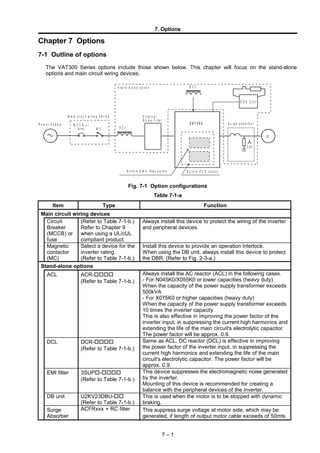
  • 1. 7. Options Chapter 7 Options 7-1 Outline of options The VAT300 Series options include those shown below. This chapter will focus on the stand-alone options and main circuit wiring devices. Fig. 7-1 Option configurations Table 7-1-a Item Type Function Main circuit wiring devices Circuit Breaker (MCCB) or fuse (Refer to Table 7-1-b.) Refer to Chapter 9 when using a UL/cUL compliant product. Always install this device to protect the wiring of the inverter and peripheral devices. Magnetic contactor (MC) Select a device for the inverter rating. (Refer to Table 7-1-b.) Install this device to provide an operation interlock. When using the DB unit, always install this device to protect the DBR. (Refer to Fig. 2-3-a.) Stand-alone options ACL ACR- (Refer to Table 7-1-b.) Always install the AC reactor (ACL) in the following cases. - For N045K0/X055K0 or lower capacities (heavy duty) When the capacity of the power supply transformer exceeds 500kVA - For X075K0 or higher capacities (heavy duty) When the capacity of the power supply transformer exceeds 10 times the inverter capacity. This is also effective in improving the power factor of the inverter input, in suppressing the current high harmonics and extending the life of the main circuit's electrolytic capacitor. The power factor will be approx. 0.9. DCL DCR- (Refer to Table 7-1-b.) Same as ACL, DC reactor (DCL) is effective in improving the power factor of the inverter input, in suppressing the current high harmonics and extending the life of the main circuit's electrolytic capacitor. The power factor will be approx. 0.9. EMI filter 3SUP- (Refer to Table 7-1-b.) This device suppresses the electromagnetic noise generated by the inverter. Mounting of this device is recommended for creating a balance with the peripheral devices of the inverter. DB unit U2KV23DBU- (Refer to Table 7-1-b.) This is used when the motor is to be stopped with dynamic braking. Surge Absorber ACFRxxx + RC filter This suppress surge voltage at motor side, which may be generated, if length of output motor cable exceeds of 50mts 7 – 1 D C L D B R U n it V A T 3 0 0 M C A C L E x te r n a l N o is e F ilt e r S u r g e a b s o r b e rM C C B o r fu s e P o w e r S u p p ly M a in c ir c u it w ir in g d e v ic e S ta n d - A lo n e o p tio n B u ilt- in P C B o p tio n M 3 p h B u ilt- in E M C filte r o p tio n
  • 2. 7. Options Table 7-1-a (continued) Built-in PCB options (These are built-in type options mounted on the basic PCB of the inverter.) Item Type (Instruction manual) Function Class Indication of rating nameplate (Note 1) Speed detection 1 (complimentary type compatible) U30V24DN1 N62P30609=1-01 (PCST-3480) This is a speed detection PCB for the complimentary output type encoder. Response frequency: Change between 60±10kHz and 20kHz. I 1 Speed detection 2 (line driver compatible) U30V24DN2 N62P30610=1-01 (PCST-3481) This is a speed detection PCB for the line driver output type encoder. Response frequency: 250kHz (signal: A, B, Z, S phase) I 2 Speed detection 3 (PM compatible) U30V24DN3 N62P30611=1-01 (PCST-3482) This is a speed (pole position) detection PCB for the PM drive control, and is compatible with the line driver output type encoder. Response frequency: 250kHz (signal: A, B, Z, U, V, W phase) I 3 Speed detection 4 (Note 2) U30V24DN4 N62P30642=1-01 (PCST-3483) Speed detection PCB compatible with Heidenhain ERN1387. 1Vp-p 2-phase, 2-set sine wave + Z-phase pulse I 4 Speed detection 6 U30V24DN6 N62P30609=2-01 (PCST-3480) This is a speed detection PCB for the single-phase complementary output type encoder circuit. The signal high level is set to 4V or more, and the low level is set to 1.0V or less. I 6 Relay interface U30V24RY0 N62P30612=1-01 (PCST-3477) This is used to expand the contact input/output points. Relay input : 4 points (PSI8 to 11) 1c contact output : 4 points (PSO4 to 7) III N Parallel interface U30V24PI0 N62P30614=1-01 (PCST-3475) This is used to receive parallel settings from the PLC. Parallel data input : 16 bits Data length : 16, 12, 8 bits selective Format : Binary or BCD selective Open collector output : 2 points (PSO4, 5) III M Insulated AI/AO (Note 2) U30V24AI0 N62P30622=1-01 (PCST-3479) An insulated 4ch analog input, analog output is possible. Analog input : 16 bits (input range ±10V) Analog output : 12 bits (output range 10V) II S Profibus-DP interface U30V24SL0 N62P30616=1-01 (PCST-3466) This is used to make a connection with the network on the Profibus-DP communication protocol. Transmission speed : 12Mbps No. of stations : 126 stations in one network III H CC-Link interface U30V24SL3 N62P30619=1-01 (PCST-3472) This is used to make a connection with the CC-Link network. Transmission speed : 156kbps, 625kbps, 2.5Mbps, 5Mbps, 10Mbps (DIP switch settings can be made.) No. of stations : 64 stations in one network III K DeviceNet interface U30V24SL2 N62P30618=1-01 (PCST-3470) This is used to make a connection with the DeviceNet network. Transmission speed : 125kbps, 250kbps, 500kbps (DIP switch settings can be made.) No. of stations : 64 stations in one network III J CANopen interface U30V24SL1 N62P30617=1-01 (PCST-3468) This is used to make a connection with the CANopen network. Transmission speed : 125kbps, 250kbps, 500kbps, 1Mbps (DIP switch settings can be made.) No. of stations : 128 stations in one network III I (Note 1) "0" indicates that the optional PCB is not installed. (Note 2) The speed detection 4 (U30V24DN4) and insulated AI/AO (U30V24AIO) cannot be used simultaneously. 7 – 2
  • 3. 7. Options Table 7-1-b Main circuit wiring device ratings, and stand-alone option preparation drawing numbers and types (Normal-duty) VAT300 Motor MCCB Line EMC Dynamic Braking DBR INPUT DC Surge Absorber (5) Type KW(1) (2) (A) MC Filter (3) Module (Note 4) AC Reactor Reactor Reactor + RC N000K7 0.75 15 CL00 Built in Built in DB TLR216P200 ACRP6A2H5 - - N001K5 1.5 15 CL00 Built in Built in DB TLR108P200 ACRP9A1H3 - - N002K2 2.2 15 CL00 Built in Built in DB TLR74P200 ACRP12A0H84 - - N004K0 4 20 CL01 Built in Built in DB TLR44P600 ACRP18A0H56 - - N005K5 5.5 30 CL02 Built in Built in DB TLR29P600 ACRP27A0H37 - - N007K5 7.5 40 CL04 U30F3075EB Built in DB TLR22P600 ACRP35A0H27 DCRP45A0H55 - N011K0 11 60 CL04 U30F3075EB Built in DB TLR15P1000 ACRP55A0H18 DCRP60A0H4 - N015K0 15 80 CL06 U30F3100EB Built in DB TLR11P1200 ACRP70A0H14 DCRP80A0H3 - N018K5 18.5 100 CL07 U30F3100EB Built in DB TLR8,8P1500 ACRP80A0H14 DCRP100A0H24 - N022K0 22 125 CL09 U30F3130EB U2KV23DBUL2 TLR7,4P1800 ACRP97A0H11 DCRP120A0H2 - N030K0 30 150 CL10 U30F3180EB U2KV23DBUL3 TLR5P2500 ACRP140A0H072 DCRP150A0H17 - N037K0 37 200 CK75 U30F3250ES U2KV23DBUL3 TLR4P3000 ACRP180A0H056 DCRP180A0H14 - N045K0 45 225 CK75 U30F3250ES U2KV23DBUL4 - ACRP200A0H051 DCRP220A0H11 - X000K7 0.75 15 CL00 Built in Built in DB TLR864P200 ACRP3A8H1 - ACFRP10A + RC X001K5 1.5 15 CL00 Built in Built in DB TLR432P200 ACRP4A5H1 - ACFRP10A + RC X002K2 2.2 15 CL00 Built in Built in DB TLR295P200 ACRP6A3H4 - ACFRP10A + RC X004K0 4 15 CL00 Built in Built in DB TLR175P600 ACRP10A2H - ACFRP10A + RC X005K5 5.5 20 CL00 Built in Built in DB TLR118P600 ACRP14A1H4 - ACFRP14A + RC X007K5 7.5 25 CL02 Built in Built in DB TLR86P600 ACRP18A1H1 DCRP25A2H1 ACFRP18A + RC X011K0 11 30 CL04 Built in Built in DB TLR59P1000 ACRP27A0H75 DCRP32A1H6 ACFRP27A + RC X015K0 15 40 CL04 Built in Built in DB TLR43P1000 ACRP35A0H58 DCRP40A1H2 ACFRP35A + RC X018K5 18.5 50 CL04 Built in Built in DB TLR35P1500 ACRP38A0H58 DCRP50A0H96 ACFRP38A + RC X022K0 22 60 CL06 Built in Built in DB TLR29P1800 ACRP45A0H45 DCRP60A0H82 ACFRP45A + RC X030K0 30 80 CL06 Built in U2KV23DBUH3 TLR22P2500 ACRP70A0H29 DCRP80A0H58 ACFRP62A + RC X037K0 37 100 CL07 U30F3100EB U2KV23DBUH3 TLR18P3000 ACRP90A0H22 DCRP100A0H49 ACFRP90A + RC X045K0 45 125 CL09 U30F3130EB U2KV23DBUH4 TLR15P3700 ACRP90A0H22 DCRP125A0H40 ACFRP90A + RC X055K0 55 150 CL09 U30F3180EB U2KV23DBUH4 - ACRP115A0H18 DCRP140A0H32 ACFRP115A + RC X075K0 75 200 CK75 U30F3250ES U2KV23DBUH4 - ACRP160A0H14 DCRP180A0H25 ACFRP160A + RC X090K0 90 225 CK08 U30F3250ES U2KV23DBUH4 - ACRP185A0H11 DCRP210A0H25 ACFRP185A + RC X110K0 110 300 CK85 U30F3320ES U2KV23DBUH4 - ACRP225A0H096 DCRP270A0H18 ACFRP300A + RC X132K0 132 350 CK09 U30F3400ES U2KV23DBUH4 - ACRP300A0H067 DCRP310A0H14 ACFRP300A + RC X160K0 160 400 CK09 U30F3600ES U2KV23DBUH4 - ACRP360A0H056 DCRP400A0H13 ACFRP360A + RC X200K0 200 500 CK95 U30F3600ES U2KV23DBUH4 - ACRP460A0H056 DCRP540A0H08 ACFRP460A + RC X250K0 250 600 CK10 U30F31000ES 2xU2KV23DBUH4 - ACRP550A0H039 DCRP650A0H07 ACFRP550A + RC X315K0 315 800 CK11 U30F31000ES 2xU2KV23DBUH4 - ACRP700A0H035 DCRP740A0H06 ACFRP700A + RC X400K0 400 1000 CK12 U30F31000ES 2xU2KV23DBUH4 - ACRP850A0H023 DCRP950A0H05 ACFRP850A + RC X475K0 475 1200 U30F31600ES 3xU2KV23DBUH4 - ACRP950A0H016 DCRP1000A0H04 ACFRP950A + RC (Note 1) Device selection conditions, for Normal Duty (Overload capacity 120%, 60s) • The input current is calculated as follows: I = (IMkW)/ηIM/ηINV/COSø/voltage/√    3 • The ηIM (motor efficiency) is 0.85 for 11kW or less, 0.9 for 15kW or more. • The ηINV (inverter efficiency) is 0.95. • COSø is 0.5 to 0.6 at the input power factor. When using ACL or DCL, recalculate as 0.9. • The power supply voltage is 200V/380V. (If the power supply voltage differs, recalculate and select.) (Note 2) Fuses or MCCB given are for IEC Ratings When complying with UL/cUL, use a UL certified fuse as indicated in section 9-1. (Note 3) Built-in EMC filters only in specified ratings and for drives U3SN_____F__ or U3SX_____F__ (Note 4) External Dynamic Braking Resistors for optimal performance. Note drives up to U3SN011K0 and U3SX11K0 include a built in DBR, which should be disconnected when using the external DBR Check 7-3-1 section. (Note 5) The Surge absorber -useful when length of motor cable is more than 50mts- is configured using the output reactor shown in above table plus RC filter, N11P34018=7 (use up to 1kHz carrier frequency) 7 – 3
  • 4. 7. Options Table 7-1-b Main circuit wiring device ratings, and stand-alone option preparation drawing numbers and types (Heavy-duty) VAT300 Motor MCCB Line EMC Dynamic Braking DBR INPUT DC Surge Absorber (5) Type KW (1) (2) (A) MC Filter (3) Module (Note 4) AC Reactor Reactor Reactor + RC N000K7 0.4 15 CL00 Built in Built in TLR405P200 ACRP4A2H5 - - N001K5 0.75 15 CL00 Built in Built in TLR216P200 ACRP6A2H5 - - N002K2 1.5 15 CL00 Built in Built in TLR108P200 ACRP9A1H3 - - N004K0 2.2 20 CL00 Built in Built in TLR74P200 ACRP12A0H84 - - N005K5 4 30 CL01 Built in Built in TLR44P600 ACRP18A0H56 - - N007K5 5.5 35 CL02 U30F3075EB Built in TLR29P600 ACRP27A0H37 DCRP32A0H78 - N011K0 7.5 50 CL04 U30F3075EB Built in TLR22P600 ACRP35A0H27 DCRP45A0H55 - N015K0 11 70 CL04 U30F3100EB Built in TLR15P1000 ACRP55A0H18 DCRP60A0H4 - N018K5 15 90 CL06 U30F3100EB Built in TLR11P1200 ACRP70A0H14 DCRP80A0H3 - N022K0 18.5 125 CL07 U30F3130EB U2KV23DBUL2 TLR8,8P1500 ACRP80A0H14 DCRP100A0H24 - N030K0 22 125 CL09 U30F3180EB U2KV23DBUL2 TLR7,4P1800 ACRP97A0H11 DCRP120A0H2 - N037K0 30 150 CL10 U30F3250ES U2KV23DBUL3 TLR5P2500 ACRP140A0H072 DCRP150A0H17 - N045K0 37 200 CK75 U30F3250ES U2KV23DBUL3 TLR4P3000 ACRP180A0H056 DCRP180A0H14 - X000K7 0.4 15 CL00 Built in Built in TLR864P200 ACRP3A8H1 - ACFRP10A + RC X001K5 0.75 15 CL00 Built in Built in TLR864P200 ACRP3A8H1 - ACFRP10A + RC X002K2 1.5 15 CL00 Built in Built in TLR432P200 ACRP4A5H1 - ACFRP10A + RC X004K0 2.2 15 CL00 Built in Built in TLR295P200 ACRP6A3H4 - ACFRP10A + RC X005K5 4 15 CL00 Built in Built in TLR175P600 ACRP10A2H - ACFRP10A + RC X007K5 5.5 20 CL00 Built in Built in TLR118P600 ACRP14A1H4 DCRP18A2H9 ACFRP14A + RC X011K0 7.5 25 CL02 Built in Built in TLR86P600 ACRP18A1H1 DCRP25A2H1 ACFRP18A + RC X015K0 11 35 CL04 Built in Built in TLR59P1000 ACRP27A0H75 DCRP32A1H6 ACFRP27A + RC X018K5 15 50 CL04 Built in Built in TLR43P1000 ACRP35A0H58 DCRP40A1H2 ACFRP35A + RC X022K0 18.5 60 CL04 Built in Built in TLR35P1500 ACRP38A0H58 DCRP50A0H96 ACFRP38A + RC X030K0 22 70 CL06 Built in U2KV23DBUH2 TLR29P1800 ACRP45A0H45 DCRP60A0H82 ACFRP45A + RC X037K0 30 80 CL06 U30F3100EB U2KV23DBUH3 TLR22P2500 ACRP70A0H29 DCRP80A0H58 ACFRP62A + RC X045K0 37 100 CL07 U30F3130EB U2KV23DBUH3 TLR18P3000 ACRP90A0H22 DCRP100A0H49 ACFRP90A + RC X055K0 45 125 CL09 U30F3180EB U2KV23DBUH4 TLR15P3700 ACRP115A0H18 DCRP125A0H40 ACFRP115A + RC X075K0 55 150 CK75 U30F3180EB U2KV23DBUH4 - ACRP115A0H18 DCRP140A0H32 ACFRP115A + RC X090K0 75 200 CK08 U30F3250ES U2KV23DBUH4 - ACRP160A0H14 DCRP180A0H25 ACFRP160A + RC X110K0 90 225 CK85 U30F3250ES U2KV23DBUH4 - ACRP185A0H11 DCRP210A0H25 ACFRP185A + RC X132K0 110 300 CK09 U30F3320ES U2KV23DBUH4 - ACRP225A0H096 DCRP270A0H18 ACFRP225A + RC X160K0 132 350 CK09 U30F3400ES U2KV23DBUH4 - ACRP300A0H067 DCRP310A0H14 ACFRP300A + RC X200K0 160 400 CK95 U30F3600ES U2KV23DBUH4 - ACRP360A0H056 DCRP400A0H13 ACFRP360A + RC X250K0 200 500 CK10 U30F3600ES U2KV23DBUH4 - ACRP460A0H056 DCRP540A0H08 ACFRP460A + RC X315K0 250 700 CK11 U30F31000ES 2xU2KV23DBUH4 - ACRP550A0H039 DCRP650A0H07 ACFRP550A + RC X400K0 315 800 CK12 U30F31000ES 2xU2KV23DBUH4 - ACRP700A0H035 DCRP740A0H06 ACFRP700A + RC X475K0 400 1000 U30F31000ES 2xU2KV23DBUH4 ACRP850A0H023 DCRP950A0H05 ACFRP850A + RC (Note 1) Device selection conditions for Heavy Duty (Overload capacity 150%, 60s) • The input current is calculated as follows: I = (IMkW)/ηIM/ηINV/COSø/voltage/√    3 • The ηIM (motor efficiency) is 0.85 for 11kW or less, 0.9 for 15kW or more. • The ηINV (inverter efficiency) is 0.95. • COSø is 0.5 to 0.6 at the input power factor. When using ACL or DCL, recalculate as 0.9. • The power supply voltage is 200V/380V. (If the power supply voltage differs, recalculate and select.) (Note 2) Fuses or MCCB given are for IEC Ratings When complying with UL/cUL, use a UL certified fuse as indicated in section 9-1. (Note 3) Built-in EMC filters only in specified ratings and for drives U3SN_____F__ or U3SX_____F__ (Note 4) External Dynamic Braking Resistors for optimal performance. Note drives up to U3SN011K0 and U3SX015K0 include a built in DBR, which should be disconnected when using the external DBR Check 7-3-1 section. (Note 5) The Surge absorber -useful when length of motor cable is more than 50mts- is configured using the output reactor shown in above table plus RC filter, N11P34018=7 (use up to 1kHz carrier frequency) 7 – 4
  • 5. 7. Options 7-2 Built-in PCB option This is a built-in type option mounted on the VAT300 control PCB. One type can be selected from option I, option II and option III. Up to three types of PCB options can be mounted at once. These PCB options are connected to the connector on the VAT300 control PCB, and can be easily mounted even after purchasing the VAT300. Refer to each instruction manual for details on the PCB options. * A dedicated PCB mounting jig is required when mounting the PCB option II and III at the same time. 7-2-1 Option classes (1) Option I This is the PCB option for speed detection 1 to 4. The mounting position I is fixed. (2) Option II This is the PCB option for the Insulated AI/AO interface, etc. The mounting position is position II. (3) Option III This is the PCB option for the relay interface, serial communication etc. The mounting position is position III. (Position III is PCB mounted on the PCB option at position II.) Refer to Table 7-1-a for the detailed option classes. Built-in PCB option mounting drawing 7 – 5 Control PCB cover Option I Option III Option II (position II) (position III) i ) (position I) i )
  • 6. 7. Options Notes for moving Operation panel folder Do not raise the operation panel folder with an angle of larger than 90°, so that the folder should not be fallen off. If the operation panel folder should be taken off, push the hinges of the folder lightly and insert them into the original positions. 7 – 6 Fig. 7-2-1-c Fig. 7-2-1-b
  • 7. 7. Options 7-3 Dynamic braking (DB) option The VAT300 has a dynamic braking option. Note) When Unit built-in DBR is used, set the DBR overload protection parameter (C22-4) to less than the actual used %ED (Max. 10.0). When the external DB unit is used, set C22-4 to 0.0. 7-3-1 Built-in DB circuit N018K0 / X022K0 and smaller The DB transistor is built in as a standard for the N018K0 / X022K0 and smaller capacities. For the N011K0/X015K0 and smaller capacities, the DB resistor (DBR) can be built in as an option. When using the DB, use at 10%ED or less as shown in Fig. 7-3-1-a. When using the dynamic braking option, set the Regenerative current limit (B18-1) and the DB option selection (C31-0 f0 ). T t2t1 Speed Fig. 7-3-1-a (1) Unit built-in DBR The specification of DBR built into the unit is shown in Table 7-3-1-a. If these resistors are applied, use within t(sec) shown in Table 7-3-1-a. Table 7-3-1-a Unit built-in DBR Inverter type VAT300 U3S_ Resistance capacity (W) Built-in DBR (Ω) Heavy-duty Normal-duty t (sec) (Note 1) Motor capacity (kW) Braking torque (%) Motor capacity (kW) Braking torque (%) N000K7 120 220 0.4 200 0.75 110 30 N001K5 120 220 0.75 110 1.5 55 30 N002K2 120 220 1.5 55 2.2 35 30 N004K0 120 180 2.2 45 4.0 25 20 N005K5 120 110 4.0 40 5.5 30 10 N007K5 120 91 5.5 35 7.5 25 10 N011K0 120 91 7.5 25 11 15 10 X000K7 120 430 0.4 340 0.75 220 10 X001K5 120 430 0.75 220 1.5 130 10 X002K2 120 430 1.5 130 2.2 75 10 X004K0 120 430 2.2 75 4.0 40 10 X005K5 120 430 4.0 40 5.5 30 10 X007K5 120 430 5.5 30 7.5 20 10 X011K0 120 430 7.5 20 11 15 10 X015K0 120 430 11 15 15 10 10 (Note 1) Set C22-4 to [t / 600sec] × 100%. 7 – 7 (position I) i )
  • 8. 7. Options (2) External DB resistor If the braking torque is insufficient with the above built-in resistor, provide an external DB resistor with a circuit as shown in Fig. 7-3-1-b. When using an external DB resistor, remove the built-in DB resistor. The resistance value and usable minimum resistance value to obtain a 100% braking torque is shown in Table 7-3-1-b. When using the external DB resistor, use of a burning prevention circuit, including the thermal relay (76D) shown in Fig. 7-3-1-b. is recommended. DBR Transistor External DB resistor 2L+1 MC ON OFF MC 76D THRY MC control sequence circuit Fig. 7-3-1-b DBR circuit Table 7-3-1-b External DBR Inverter type VAT300 U3S_ Heavy-duty Normal-duty Motor capacity (kW) 100% braking resistance type Motor capacity (kW) 100% braking resistance type N000K7 0.4 TLR405P200 0.75 TLR216P200 N001K5 0.75 TLR216P200 1.5 TLR108P200 N002K2 1.5 TLR108P200 2.2 TLR74P200 N004K0 2.2 TLR74P200 3.7 TLR44P600 N005K5 4.0 TLR44P600 5.5 TLR29P600 N007K5 5.5 TLR29P600 7.5 TLR22P600 N011K0 7.5 TLR22P600 11 TLR15P1000 N015K0 11 TLR15P1000 15 TLR11P1200 N018K5 15 TLR11P1200 18 TLR8,8P1500 X000K7 0.4 TLR864P200 0.75 TLR864P200 X001K5 0.75 TLR864P200 1.5 TLR432P200 X002K2 1.5 TLR432P200 2.2 TLR295P200 X004K0 2.2 TLR295P200 3.7 TLR175P600 X005K5 4.0 TLR175P600 5.5 TLR118P600 X007K5 5.5 TLR118P600 7.5 TLR86P600 X011K0 7.5 TLR86P600 11 TLR59P1000 X015K0 11 TLR59P1000 15 TLR43P1000 X018K5 15 TLR43P1000 18 TLR35P1500 X022K0 18 TLR35P1500 22 TLR29P1800 7 – 8
  • 9. 7. Options Table 7-3-1-c External DBR Dimensions Resistance Wire Dimensions (Note1) (mm2 ) A B C D E G Type TLR405P200 2.5 215 80 235 40 ∅ - - 1(*) TLR216P200 2.5 215 80 235 40 ∅ - - 1(*) TLR108P200 2.5 215 80 235 40 ∅ - - 1(*) TLR74P200 2.5 215 80 235 40 ∅ - - 1(*) TLR44P600 2.5 430 95 460 57 - - 1 TLR29P600 2.5 430 95 460 57 - - 1 TLR22P600 2.5 430 95 460 57 - - 1 TLR15P1000 2.5 430 105 460 66 - - 1 TLR11P1200 4 430 125 460 80 - - 1 TLR864P200 2.5 215 80 235 40 ∅ - - 1(*) TLR432P200 2.5 215 80 235 40 ∅ - - 1(*) TLR295P200 2.5 215 80 235 40 ∅ - - 1(*) TLR175P600 2.5 430 95 460 57 - - 1 TLR118P600 2.5 430 95 460 57 - - 1 TLR86P600 2.5 430 95 460 57 - - 1 TLR59P1000 2.5 430 105 460 66 - - 1 TLR43P1000 2.5 430 105 460 66 - - 1 TLR35P1500 2.5 430 105 460 139 105 65 2 Note 1 Recommended resistor is rated for a ED of 10%, with maximum braking time of 20 sec. For braking large inertia loads, ask your supplier for an appropriate resistor. Note that VAT300 up to N011K5 and up to X015K5, include DB resistor as shown in table 7- 3-1a. This should be disconnected when using external resistors Type 1(*) As type 1, but provided with 210mm output cable (No terminals) 7 – 9 D B B T y p e 1 T y p e 2 A C D B B A C G E
  • 10. 7. Options 7-3-2 External DB unit N022K0 / X030K0 and higher Use an external DB unit when carrying out dynamic braking with the N022K0/X030K0 and larger unit. Applicable DB unit, the resistance value and usable minimum resistance value to obtain a 100% braking torque, is shown in Table 7-3-2. Connect the DB unit as shown in Fig. 7-3-2. When carrying out dynamic braking with one DB unit, use at 10%ED or less as shown in Fig. 7-3-1-a. If the braking torque is insufficient with one unit, connect a DB unit in parallel. Set in module U2KV23DBU the parameters A0.x and A1.x at least. Check manual of U2KV23DBU. L- M L1 L2 L3 B L+L-L+ MC L+1 L+2 L- MC 76D THRY VAT300 B 又は U V W MC MC ON OFF DB unit No. 1 (V23DBU-) DB unit No. 2 (V23DBU-)MC control sequence circuit DB resistor DB resistor DB unit Fault Fig. 7-3-2 DB unit connection Table 7-3-2 External DB unit Inverter type VAT300 U3S_ Heavy-duty Normal-duty Moto r (kW) DB u n i t t y p e U2KV23_ 100% braking resistance (3) Motor (kW) DB u n i t t y p e U2 KV23_ 100% braking resistance (3) N022K0 18 DBUL2 TLR8,8P1500 22 DBUL2 TLR7,4P1800 N030K0 22 TLR7,4P1800 30 DBUL3 TLR5P2500 N037K0 30 DBUL3 TLR5P2500 37 TLR4P3000 N045K0 37 TLR4P3000 45 DBUL4 (4) 3.8Ω X030K0 22 DBUH2 TLR29P1800 30 DBUH3 TLR22P2500 X037K0 30 DBUH3 TLR22P2500 37 TLR18P3000 X045K0 37 TLR18P3000 45 DBUH4 TLR15P3700 X055K0 45 DBUH4 TLR15P3700 55 (4) 12.5Ω X075K0 55 (4) 12.5Ω 75 (4) 9.2Ω X090K0 75 (4) 9.2Ω 90 (4) 7.7Ω X110K0 90 (4) 7.7Ω 110 (4) 6.3Ω X132K0 110 (4) 6.3Ω 132 (4) 5.2Ω X160K0 132 (4) 5.2Ω 160 (4) 4.3Ω X200K0 160 (4) 4.3Ω 200 (4) 3.4Ω X250K0 200 (4) 3.4Ω 250 DBUH4 × 2 units (4) 5.6Ω × 2 sets X315K0 250 DBUH4 × 2 units (4) 5.6Ω × 2 sets 315 (4) 4.4Ω × 2 sets X400K0 315 (4) 4.4Ω × 2 sets 400 (4) 3.4Ω × 2 sets X475K0 400 (4) 3.4Ω × 2 sets 475 DBUH4 × 3 units (4) 4.5Ω × 3 sets 7 – 10
  • 12. 7. Options (1) Set the following parameters when using external DB unit. C31-0 f1 = 2 : With DB B18-1 = 100% : Regenerative current limit B22-5 = 100% : Regenerative current limit (Auxiliary drive0) B26-5 = 100% : Regenerative current limit (Auxiliary drive1) B2A-5 = 100% : Regenerative current limit (Auxiliary drive2) B2E-5 = 100% : Regenerative current limit (Auxiliary drive3) (2) Obtain the power generation capacity and DBR resistance value with the following expressions. Power generation capacity (kW) = Regenerative torque Motor rated torque × 0.85× Motor capacity (kW) DBR resistance value = K Power generation capacity Note that for the 200V Series, K = 148.2 For the 400V Series, K = 593 (3) GE standard resistors TLRxxx are given for drives up to X055K0, and 5%ED. Ask your dealer for bigger ratings or heavier duty usage (4) Braking resistors for ratings above X055K0 are are only available by special request to GE. Resistance value is shown in ohms. Ask your dealer for details 3.2-3 Dimensions of external Dynamic Braking Resistors and Braking Units (1) External Resistors (2) External Braking Units 7 – 12 Resistance Wire Dimensions (Note1) (mm2 ) A B C D E G Type TLR8,8P1500 4 430 105 460 139 105 65 2 TLR7,4P1800 6 430 105 460 139 105 65 2 TLR5P2500 16 430 105 460 207 185 136 2 TLR4P3000 16 410 180 430 139 119 68 2 TLR29P1800 4 430 105 460 139 105 65 2 TLR22P2500 6 430 105 460 207 185 136 2 TLR18P3000 16 410 180 430 139 119 68 2 TLR15P3700 16 410 180 430 139 119 68 2 D B B T y p e 1 T y p e 2 A C D B B A C G E
  • 13. 7. Options 1 3 1 8 02 5 .5 2 5 .5 1 3 3 1 2 9 186 198 66 6 1 4 5 1 0 81 8 . 5 2 0 9 2 0 5 180 198 99 6 1 8 .5 U2KV23DBUL1, L2, L3 U2KV23DBUH4 U2KV23DBUH1, H2, H3 7-4 AC Reactors, DC Reactors and Surge absorbers Select the ACL and DCL according to the Table 7-1-b inverter type. Refer to Table 7-4-a, Table 7-4-b and Table 7-4-c for the outline dimension. The ACL is equivalent to a 3% impedance of the inverter capacity. Table 7-4-a Outline dimensions of ACL DIMENSIONS (mm) Weight Losses Catalolg # Drawing A B C D E Ø (kg) W ACRP4A2H5 1 120 80 152 41 100 6 1,3 16 ACRP6A2H5 1 120 80 152 41 100 6 1,5 18 ACRP9A1H3 1 120 80 152 41 100 6 1,6 17 ACRP12A0H84 1 120 80 152 41 100 6 1,7 18 ACRP18A0H56 1 120 90 152 51 100 6 2,4 21 ACRP27A0H37 1 150 95 183 46 125 6 3,3 32 ACRP35A0H27 1 150 95 183 46 125 6 3,7 35 ACRP55A0H18 1 150 110 183 61 125 6 5,5 42 ACRP70A0H14 1 150 111 250 77 100 9 5,6 100 ACRP80A0H14 1 150 121 250 87 100 9 7,1 108 ACRP97A0H11 1 150 126 250 92 100 9 7,8 124 ACRP140A0H072 3 180 166 216 92 120 9 11,9 155 ACRP180A0H056 3 180 176 216 102 120 9 14,2 175 ACRP200A0H051 3 180 186 216 112 120 9 15,9 210 ACRP3A8H1 1 120 80 152 41 100 6 1,4 17 ACRP4A5H1 1 120 80 152 41 100 6 1,5 16 ACRP6A3H4 1 120 80 152 41 100 6 1,7 19 ACRP10A2H 1 120 90 152 51 100 6 2,5 23 ACRP14A1H4 1 150 95 178 46 125 6 3,2 29 ACRP18A1H1 1 150 95 178 46 125 6 4 35 ACRP27A0H75 1 150 106 233 72 100 9 4,8 77 ACRP35A0H58 1 150 111 233 77 100 9 5,5 98 ACRP38A0H58 1 150 116 233 82 100 9 6,4 96 ACRP45A0H45 1 150 121 233 87 100 9 7,1 102 ACRP70A0H29 1 150 151 250 117 100 9 11 147 ACRP90A0H22 1 180 136 286 102 120 9 13,1 158 ACRP115A0H18 1 180 156 301 122 120 9 16,9 186 ACRP160A0H14 3 240 181 288 107 160 9 25,7 268 ACRP185A0H11 3 240 181 288 107 160 9 26,3 255 ACRP225A0H096 3 240 191 288 117 160 9 30,7 305 ACRP300A0H067 3 240 226 288 142 160 9 40,4 356 ACRP360A0H056 3 240 226 288 142 160 9 42,2 425 ACRP460A0H056 3 300 258 400 142 200 9 64,1 595 7 – 13
  • 14. 7. Options ACRP550A0H039 3 300 258 400 142 200 9 64,9 636 ACRP700A0H035 3 360 316 472 202 300 11 116,2 991 ACRP850A0H023 3 420 296 544 178 350 11 115 856 ACRP950A0H016 3 420 306 544 188 350 11 123,6 934 E A D B F ig . 1 C E A D B F ig . 3 C 7 – 14
  • 15. 7. Options Table 7-4-b Outline dimensions of DCL DIMENSIONS (mm) Weight Losses Catalolg # Drawing A B C D E Ø (kg) W DCRP32A0H78 5 100 110 173 91 75 6 3,9 37 DCRP45A0H55 5 120 110 203 86 90 6 6,1 33 DCRP60A0H4 5 120 120 220 96 90 6 6,4 41 DCRP80A0H3 5 120 135 220 111 90 6 7,1 45 DCRP100A0H24 5 120 135 235 111 90 6 7,1 51 DCRP120A0H2 5 160 150 285 130 120 9 13,4 43 DCRP150A0H17 5 160 160 285 140 120 9 15 50 DCRP180A0H14 6 160 156 288 82 120 9 11,6 71 DCRP220A0H11 6 160 161 288 87 120 9 12,9 77 DCRP18A2H9 5 100 95 178 76 75 6 3,5 42 DCRP25A2H1 5 100 95 183 76 75 6 3,5 54 DCRP32A1H6 5 100 110 183 91 75 6 3,9 59 DCRP40A1H2 5 100 110 183 91 75 6 3,9 56 DCRP50A0H96 5 120 110 209 86 90 6 6,1 60 DCRP60A0H82 5 120 120 226 96 90 6 6,4 65 DCRP80A0H58 5 120 135 226 111 90 6 7,1 58 DCRP100A0H49 5 120 135 241 111 90 6 7,1 91 DCRP125A0H40 5 160 150 293 130 120 9 13,4 79 DCRP140A0H32 5 160 150 293 130 120 9 3,9 74 DCRP180A0H25 6 160 186 288 112 120 9 18,3 92 DCRP210A0H25 6 160 216 288 142 120 9 24,2 132 DCRP270A0H18 6 160 226 288 152 120 9 27,7 127 DCRP310A0H14 6 160 246 288 162 120 9 29,8 151 DCRP400A0H13 6 200 231 400 147 150 9 40,9 190 DCRP540A0H08 6 200 251 400 157 150 9 45,7 212 DCRP650A0H07 6 200 281 400 177 150 9 56,2 237 DCRP740A0H06 6 200 296 400 192 150 9 61,6 265 DCRP950A0H05 6 240 356 472 252 180 11 99,3 256 DCRP1000A0H04 6 240 366 472 262 180 11 103,1 257 E D A B F ig . 5 C E A F ig . 6 D B C 7 – 15
  • 16. 3 0 0 2 0 0 D 7 580 7 600 5 0 5 0 10 7. Options 7.4.1 Surge Absorbers Surge absorber usage is shown on Table 7-1b, for both Normal Duty and Heavy duty ratings. Other details are given below. Surge absorber is composed by two items, ACFR reactor and RC filters DIMENSIONS (mm) Weight Losses Catalolg # Drawing A B C D E Ø (kg) W ACFRP10A 1 120 80 152 41 100 6 1,2 16 ACFRP14A 1 120 80 152 41 100 6 1,2 15 ACFRP18A 1 120 80 152 41 100 6 1,2 17 ACFRP27A 1 120 80 157 41 100 6 1,4 18 ACFRP35A 1 120 90 157 51 100 6 2,2 21 ACFRP38A 1 120 90 157 51 100 6 2,2 21 ACFRP45A 1 150 110 183 67 125 6 4,1 33 ACFRP62A 1 150 101 250 67 100 9 4,2 66 ACFRP90A 1 150 121 250 87 100 9 7,5 84 ACFRP115A 1 180 131 299 97 120 9 12,1 112 ACFRP160A 3 180 211 216 137 120 9 21,1 183 ACFRP185A 3 240 181 288 107 160 9 25,5 218 ACFRP225A 3 240 216 288 142 160 9 36,6 304 ACFRP300A 3 300 231 400 147 200 9 59,3 477 ACFRP360A 3 300 266 400 182 200 9 78,3 593 ACFRP460A 3 360 308 472 212 300 11 122,4 728 ACFRP550A 3 360 338 472 242 300 11 145,8 863 ACFRP700A 3 420 371 544 273 350 11 209,7 1486 ACFRP850A 3 480 446 616 328 400 11 336,3 1104 ACFRP950A 3 480 476 616 358 400 11 377 1267 Catalolg # RC Drawing VAT300 setting for CF Weight (kg) Losses W N11P34018=7 Fig. 06 Maximum Carrier frequency 1kHz 297 E A D B F ig . 1 C E A D B F ig . 3 C 7 – 16 D= 135mm for N11P34018=7 Fig. 06, RC Filter ACR
  • 17. 7. Options 7-5 EMI filter EMC compliance for VAT300 is achieved either by either built-in filters in the drive or by external filters. Built in filters are available for drives up to 30KW/400V (U30SX030K0_) only. For larger drives, an external EMI filter should be used when complience with EMC is required. Check table 7-1-b or the tables below to select the filter according to inverter type Table 7.5.1 VAT300 Drives with Built-in Filter VAT300 Series VAT300 Model Second Environment EN61800-3 Category C3 First Environment EN61800-3 Category C2 Filter type Add ferrite cores 200V Series with built in filter U30N000K7F__ Built-in the drive P:ZCAT3035-1330× 3 C:ZCAT3035-1330× 1 M:ZCAT3035-1330× 1 U30N001K5F__ U30N002K2F__ U30N004K0F__ NA U30N005K5F__ 400V Series with built in filter U30X000K7F__ Built-in the drive P:ZCAT3035-1330×3 C:ZCAT3035-1330×1 M:ZCAT3035-1330×1 U30X001K5F__ U30X002K2F__ U30X004K0F__ U30X005K5F__ U30X007K5F__ Built-in the drive NA U30X011K0F__ U30X015K0F__ U30X018K5F__ U30X022K0F__ U30X030K0F__ *2) P: Ferrite cores for power cable; C: Ferrite cores for control cable; M: Ferrite cores for motor cable Table 7.5.2 External filters for VAT300 drives without Built-in Filter (200V series) VAT300 Series VAT300 Model Second Environment (EN61800-3 Category C3) External filter selection Use with VAT300 in ND Use with VAT300 in HD 200V Series U30N000K7S__ U30F3016EB U30F3016EB U30N001K5S__ U30F3016EB U30F3016EB U30N002K2S__ U30F3016EB U30F3016EB U30N004K0S__ U30F3030EB U30F3030EB U30N005K5S__ U30F3030EB U30F3030EB U30N007K5S__ U30F3075EB U30F3075EB U30N011K0S__ U30F3075EB U30F3075EB U30N015K0S__ U30F3100EB U30F3100EB U30N018K5S__ U30F3100EB U30F3100EB U30N022K0S__ U30F3130EB U30F3130EB U30N030K0S__ U30F3180EB U30F3180EB U30N037K0S__ U30F3250ES U30F3250ES U30N045K0S__ U30F3250ES U30F3250ES 7 – 17
  • 18. 7. Options Table 7.5.3 External filters for VAT300 drives without Built-in Filter (400V series) VAT300 Series VAT300 Model Second Environment (EN61800-3 Category C3) External filter selection Use with VAT300 (ND) Use with VAT300 (HD) 400V U30X000K7S__ U30F3016EB U30F3016EB Series U30X001K5S__ U30F3016EB U30F3016EB U30X002K2S__ U30F3016EB U30F3016EB U30X004K0S__ U30F3016EB U30F3016EB U30X005K5S__ U30F3030EB U30F3030EB U30X007K5S__ U30F3030EB U30F3030EB U30X011K0S__ U30F3030EB U30F3030EB U30X015K0S__ U30F3055EB U30F3055EB U30X018K5S__ U30F3055EB U30F3055EB U30X022K0S__ U30F3075EB U30F3075EB U30X030K0S__ U30F3100EB U30F3100EB U30X037K0S__ U30F3100EB U30F3100EB U30X045K0S__ U30F3130EB U30F3130EB U30X055K0S__ U30F3180EB U30F3180EB U30X075K0S__ U30F3250ES U30F3180EB U30X090K0S__ U30F3250ES U30F3250ES U30X110K0S__ U30F3320ES U30F3320ES U30X132K0S__ U30F3400ES U30F3320ES U30X160K0S__ U30F3600ES U30F3400ES U30X200K0S__ U30F3600ES U30F3600ES U30X250K0S__ U30F31000ES U30F3600ES U30X315K0S__ U30F31000ES U30F31000ES U30X400K0S__ U30F31000ES U30F31000ES U30X475K0S__ U30F31600ES U30F31000ES 7 – 18
  • 19. 7. Options 7.5.1 External filter dimensions, Book case type Dimensions Weight EMI Filter L L-1 H W X Y M D Kg U30F3016EB 250 220 70 45 235 25 M5 M5 1.7 U30F3030EB 270 240 85 50 255 30 M5 M5 1.8 U30F3055EB 250 220 90 85 235 60 M6 M5 3.1 U30F3075EB 270 240 135 80 255 60 M6 M6 4 U30F3100EB 270 240 150 90 255 65 M10 M6 5.5 U30F3130EB 270 240 150 90 255 65 M10 M6 7.5 U30F3180EB 380 350 170 120 365 102 M10 M6 11 7.5.1 External filter dimensions, Standard brick case type Dimensions Weight EMI Filter W W1 X L L1 Y H H1 K M D D1 F I PE Kg U30F3250ES 190 140 165 300 392 240 116 41 20 Ø12 15 42 Ø11 40 M10 7 U30F3320ES 260 210 235 300 392 240 116 41 20 Ø12 15 42 Ø11 60 M10 10.3 U30F3400ES 260 210 235 300 392 240 116 41 20 Ø12 15 42 Ø11 60 M10 10.3 U30F3600ES 260 210 235 300 392 240 116 48,5 20 Ø12 15 42 Ø11 60 M10 11 U30F31000ES 280 230 255 350 460 290 166 64 25 Ø12 25 50 Ø17 65 M12 18 U30F31600ES 300 250 275 400 592 340 166 61 25 Ø12 25 52 Ø17 80 M12 27 7 – 19