PWM Buck Converter using Average Model
•Descargar como PPTX, PDF•
4 recomendaciones•2,944 vistas

This document is Conceptkit of PWM Buck Converter using Average Model using PSpice. pre-version, Bee Technologies prepare to products now.

Recomendados
Más contenido relacionado
La actualidad más candente
La actualidad más candente (20)
Similar a PWM Buck Converter using Average Model
Similar a PWM Buck Converter using Average Model (20)
Más de Tsuyoshi Horigome
Más de Tsuyoshi Horigome (20)
Último
Último (20)
PWM Buck Converter using Average Model
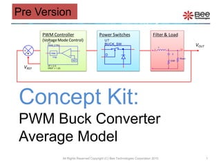
- 1. Concept Kit:PWM Buck Converter Average Model All Rights Reserved Copyright (C) Bee Technologies Corporation 2010 1 Pre Version
- 2. Contents Concept of Simulation Buck Converter Circuit Switches Filter & Load 4.1 Inductor 4.2 Capacitor PWM Controller 5.1 Error Amp. 5.2 PWM Stabilizing the Converter (Example) Load Transient Response Simulation (Example) Type 2 Compensator Calculator Simulation Index All Rights Reserved Copyright (C) Bee Technologies Corporation 2010 2
- 4. C
- 5. ESR
- 8. 2.Buck Converter Circuit All Rights Reserved Copyright (C) Bee Technologies Corporation 2010 4 Power Switches Filter & Load PWM Controller
- 11. 4.1 Filter & Load: Inductor All Rights Reserved Copyright (C) Bee Technologies Corporation 2010 6 Inductor Value The output inductor value is selected to set the converter to work in CCM (Continuous Current Mode) or DCM (Discontinuous Current Mode). Calculated by Where LCCM is the inductor that make the converter to work in CCM. VI,max is input maximum voltage RL(max) is load resistance at the minimum output current (IOUT) fosc is switching frequency (1)
- 14. 5.2 PWM Controller: PWM All Rights Reserved Copyright (C) Bee Technologies Corporation 2010 9 The PWM block is used to transfer the error voltage (between FB and REF) to be the duty cycle. The error voltage (vcomp) will be compared with sawtooth signal ( amplitude = VP ) to create the pulse that the duty cycle depends on the vcomp Transfer function of the PWM block is d = vcomp/ VP GPWM = 1/VP VP Duty cycle (d) is a value from 0 to 1
- 16. 6.Stablilizing the Converter (Example) All Rights Reserved Copyright (C) Bee Technologies Corporation 2010 11 Specification: VOUT = 5V VIN = 7 ~ 40V ILOAD = 0.2 ~ 1A L = 330uH, C = 330uF (ESR = 100m), Rupper = 3.1k, Rlower = 1k, PWM Controller: fOSC = 52kHz VP = 2.5V VREF = 1.23V Task: to find out the element of the Type 2 compensator ( R2, C1, and C2 ) G(s) e.g. Characteristics from National Semiconductor Corp. IC: LM2575
- 17. 6.Stablilizing the Converter (Example) All Rights Reserved Copyright (C) Bee Technologies Corporation 2010 12 The element of the Type 2 compensator ( R2, C1, and C2 ), that stabilize the converter, can be extracted by using Type 2 Compensator Calculator (Excel sheet) and open-loop simulation with the average models (ac models). Step2 Set C1=1kF, C2=1fF, and R2= calculated value (Rupper//Rlower) as the initial values. Step1 Open the loop with LoL=1kH and CoL=1kF then inject the ac signal to generate Bode plot.
- 18. 6.Stablilizing the Converter (Example) All Rights Reserved Copyright (C) Bee Technologies Corporation 2010 13 Step3 Select a crossover frequency (fc < fosc/4), for this example, 10kHz is selected. Then complete the table. Calcuted value of the Rupper//Rlower
- 19. All Rights Reserved Copyright (C) Bee Technologies Corporation 2010 14 6.Stablilizing the Converter (Example) If the VP ( sawtooth signal amplitude ) does not informed by the datasheet, It can be approximate from the characteristics below. from d = vcomp/ VP Suppose that the error amp. gain is 100. vcomp =gain (-vFB)then d = (100 (-vFB) ) / VP From the graph on the left, vFB = -25mV VP = (100 (-vFB) ) / d VP ≈ (100 (-(-25mV)) ) / 1 ≈ 2.5V vFB = -25mV d = 1 (100%) LM2575: Feedback Voltage vs. Duty Cycle
- 20. All Rights Reserved Copyright (C) Bee Technologies Corporation 2010 15 6.Stablilizing the Converter (Example) Gain: T(s) = H(s)GPWM Step4 Read the Gain and Phase value at the crossover frequency (10kHz) from the Bode plot, Then put the values to the table . Phase atfc Tip: To bring cursor to the fc = 10kHz type “ sfxv(10k) ” in Search Command. Cursor Search
- 21. 6.Stablilizing the Converter (Example) All Rights Reserved Copyright (C) Bee Technologies Corporation 2010 16 Step5 Select the desired amount of phase margin you need at fc ( > 45 ). Then change the K value until it gives the satisfied phase margin, for this example K=25 is chosen for Phase margin = 46. R2, C1, and C2 are calculated K Factor, introduce by Dean Venable, enable the circuit designer to choose a loop cross-over frequency and phase margin, and then determine the necessary component values to achieve these results from a few straight-forward algebraic equations.
- 22. 6.Stablilizing the Converter (Example) All Rights Reserved Copyright (C) Bee Technologies Corporation 2010 17 The element of the Type 2 compensator ( R2, C1, and C2 ) extraction can be completed by Type 2 Compensator Calculator (Excel sheet) with the converter average models (ac models) and open-loop simulation. The calculated values of the type 2 elements are, C1=0.778nF, C2=21.6pF, and R2=122.780k. *Analysis directives: .AC DEC 100 0.1 10MEG
- 23. All Rights Reserved Copyright (C) Bee Technologies Corporation 2010 18 6.Stablilizing the Converter (Example) Gain: T(s) = H(s) G(s)GPWM Phase atfc Phase margin = 45.930 at the cross-over frequency - fc = 9.778kHz. Tip: To bring cursor to the cross-over point (gain = 0dB) type “ sfle(0) ” in Search Command. Cursor Search
- 24. 7. Load Transient Response Simulation (Example) All Rights Reserved Copyright (C) Bee Technologies Corporation 2010 19 The converter, that have been stabilized, are connected with step-load to perform load transient response simulation. 5V/2.5 = 0.2A step to 0.2+0.8=1.0A load *Analysis directives: .TRAN 0 20ms 0 1u