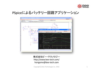
PSpiceによるバッテリー回路アプリケーション
•
0 recomendaciones•2,869 vistas

PSpiceによるバッテリー回路アプリケーションのシミュレーションの事例(PDFバージョン)

Recomendados
Recomendados
Más contenido relacionado
La actualidad más candente
La actualidad más candente (16)
Destacado
Destacado (20)
Similar a PSpiceによるバッテリー回路アプリケーション
Similar a PSpiceによるバッテリー回路アプリケーション (20)
Más de Tsuyoshi Horigome
Más de Tsuyoshi Horigome (20)
Último
Último (20)
PSpiceによるバッテリー回路アプリケーション
- 1. PSpiceによるバッテリー回路アプリケーション 株式会社ビー・テクノロジー http://www.bee-tech.com/ horigome@bee-tech.com Copyright (C) Bee Technologies Inc. 2010 1
- 2. EDA Designer Technology Device of Model Simulation Copyright (C) Bee Technologies Inc. 2010 2
- 3. モデル デザインキット 回路方式のテンプレート 回路解析シミュレータ PSpice (ABMライブラリーが豊富) ABM=Analog Behavior Model Copyright (C) Bee Technologies Inc. 2010 3
- 4. http://www.bee-tech.com/ Copyright (C) Bee Technologies Inc. 2010 4
- 5. スパイス・パーク http://www.spicepark.com/ 55種類のデバイス、3,328モデル(2010年7月29日現在)をご提供中。 現在、グローバル版スパイス・パークを準備中。 Copyright (C) Bee Technologies Inc. 2010 5
- 6. Bee Style: http://www.spicepark.com/ スパイス・パークのログイン後トップページにて、PDFでバックナンバーも含め PDF形式で参照及びダウンロード出来ます。 Copyright (C) Bee Technologies Inc. 2010 6
- 7. バッテリーのスパイスモデルの推移 放電特性 放電特性 充電特性 付加抵抗 付加抵抗 + 一定 可変 放電特性 リチウムイオン電池 ニッケル水素電池 鉛蓄電池 Copyright (C) Bee Technologies Inc. 2010 7
- 8. Copyright (C) Bee Technologies Inc. 2010 8
- 9. Design Kit PV Li-Ion Battery System Copyright (C) Bee Technologies Inc. 2010 9
- 10. 1.1 Lithium-Ion Batteries Pack Specification BAYSUN’s Lithium-Ion Batteries Pack : Power Battery Plus (PBT-BAT-0001) • Capacity............................65[Wh], 4400[mAh] (Approximately) • Rated Current....................3[A] • Input Voltage.......................20.5 [Vdc] • Output Voltage....................12.8 ~ 16.4 [Vdc] ( 4 cells ) • Charging time......................5[hours] (Approximately) Copyright (C) Bee Technologies Inc. 2010 10
- 11. 1.2 Discharge Time Characteristics 18V D1 DMOD PARAMETERS: Voch 16V rate = 1 16.8Vdc CAh = 4400m 0 Hi 0.2C ( 880 mA ) 0 C1 U1 14V 0.5C ( 2200 mA ) IN+ OUT+ 1n + - PBT-BAT-0001 IN- OUT- G1 0 TSCALE = 3600 GVALUE SOC1 = 100 1C ( 4400 mA ) limit(V(%IN+, %IN-)/0.01, 0, rate*CAh ) 12V TSCALE=3600 means 0 time Scale (Simulation time : Real time) is Batteries Pack Model Parameters 1:3600 10V NS (number of batteries in series) = 4 cells C (capacity) = 4400 mA SOC1 (initial state of charge) = 100% 8V TSCALE (time scale) , simulation : real time 0s 1.0s 2.0s 3.0s 4.0s 5.0s 6.0s 1 : 3600s or V(Hi) 1s : 1h Time Discharge Rate : 0.2C(880mA), 0.5C(2200mA), and 1C(4400mA) Copyright (C) Bee Technologies Inc. 2010 11
- 12. 1.3 Single Cell Discharge Characteristics Single cell Measurement Simulation 4.50 0.2C ( 880mA ) 0.5C ( 2200mA ) 1.0C ( 4400mA ) 4.00 VOLTAGE [V] 3.50 3.00 2.50 2.00 100 90 80 70 60 50 40 30 20 10 0 -10 SOC [%] • Single cell discharge characteristics are compared between measurement data and simulation data. Copyright (C) Bee Technologies Inc. 2010 12
- 13. 1.4 Charge Time Characteristics SOC [%] D1 100V PARAMETERS: rate = 0.2 DMOD CAh = 4400m 80V G1 Voch GVALUE 16.8Vdc Limit(V(%IN+, %IN-)/0.1, 0, rate*CAh ) 0 Hi 60V OUT+ OUT- C1 U1 0 40V 1n + - PBT-BAT-0001 IN+ IN- 0 TSCALE = 3600 20V SOC1 = 0 Vin 20.5Vdc SEL>> 0V Vbatt [V] ICharge [A] V(X_U1.SOC) 0 18V 5.0A 1 2 Batteries Pack Model Parameters 16V 4.0A NS (number of batteries in series) = 4 cells C (capacity) = 4400 mA 14V 3.0A SOC1 (initial state of charge) = 100% TSCALE (time scale) , simulation : real time 12V 2.0A 1 : 3600s or 1s : 1h 10V 1.0A Charger Adaptor >> 8V 0A Input Voltage = 20.5 Vdc 0s 1.0s 2.0s 3.0s 4.0s 5.0s 6.0s 7.0s Input Current = 880 mA(max.) 1 V(Hi) 2 I(U1:PLUS) Time Copyright (C) Bee Technologies Inc. 2010 13
- 14. 2.1 Solar Cells Specification BP Solar’s photovoltaic module : SX330 • Maximum power (Pmax)..............30[W] • Voltage at Pmax (Vmp).............16.8[V] • Current at Pmax (Imp)...............1.78[A] 502mm • Short-circuit current (Isc)...........1.94[A] • Open-circuit voltage(Voc)...........21.0[V] 595mm Copyright (C) Bee Technologies Inc. 2010 14
- 15. 2.2 Output Characteristics vs. Incident Solar Radiation SX330 Output Characteristics vs. Incident Solar Radiation 2.5A SOL=1 2.0A Current (A) 1.5A SOL=0.5 + 1.0A U1 0.5A SOL=0.16 SX330 0A SX330 SOL = 1 I(Isence) 40W SOL=1 30W Power (W) 20W Parameter, SOL is added as SOL=0.5 normalized incident radiation, 10W SOL=0.16 where SOL=1 for AM1.5 conditions SEL>> 0W 0V 5V 10V 15V 20V 25V 30V I(Isence)* V(V1:+) V_V1 Voltage (V) Copyright (C) Bee Technologies Inc. 2010 15
- 16. 3. Solar Cell Battery Charger • Solar Cell charges the Li-ion batteries pack (PBT-BAT-001) with direct connect technique. Choose the solar cell that is able to provide current at charging rate or more with the maximum power voltage 100V (Vmp) nears the batteries pack charging voltage. 80V • PBT-BAT-0001 (Li-ion batteries pack) 60V – Charging time is approximately 5 hours with charging rate 0.2C or 880mA 40V – Voltage during charging with 0.2C is between 14.7 to 16.9 V 20V 0V V(X_U1.SOC) 18V 5.0A 1 2 16.9 V 16V 4.0A 14.7 V 14V 3.0A 12V 2.0A 0.2C or 880mA 10V 1.0A SEL>> 8V 0A 0s 1.0s 2.0s 3.0s 4.0s 5.0s 6.0s 7.0s 1 V(Hi) 2 I(U1:PLUS) Time Copyright (C) Bee Technologies Inc. 2010 16
- 17. 3.1 Concept of Simulation PV Li-Ion Battery Charger Circuit Over Voltage Protection Circuit Short circuit current ISC depends on condition: SOL 16.8V Clamp Circuit Photovoltaic Lithium-Ion Module Batteries Pack SX 330 (BP Solar) PBT-BAT-0001 (BAYSUN) Vmp=16.8V DC12.8~16.4V (4 cells) Pmax=30W 4400mAh Copyright (C) Bee Technologies Inc. 2010 17
- 18. 3.2 PV Li-Ion Battery Charger Circuit D1 PARAMETERS: DMOD sol = 1 Voch 16.8Vdc pv 0 Hi + C1 U1 0 U2 1n + - PBT-BAT-0001 SX330 SX330 SOL = {sol} 0 TSCALE = 3600 SOC1 = 0 0 • Input value between 0-1 in the “PARAMETERS: sol = ” to set the normalized incident radiation, where SOL=1 for AM1.5 conditions. Copyright (C) Bee Technologies Inc. 2010 18
- 19. 3.3 Charging Time Characteristics vs. Weather Condition 100V 80V 60V 40V sol = 1.00 20V sol = 0.50 sol = 0.16 0V 0s 1s 2s 3s 4s 5s 6s 7s 8s 9s 10s V(X_U1.SOC) Time • Simulation result shows the charging time for sol = 1, 0.5, and 0.16. Copyright (C) Bee Technologies Inc. 2010 19
- 20. 3.4 Concept of Simulation PV Li-Ion Battery Charger Circuit + Constant Current Over Voltage Protection Circuit Short circuit current ISC depends on condition: SOL 16.8V Clamp Circuit Constant Photovoltaic Current Lithium-Ion Module Control Batteries Pack Circuit SX 330 (BP Solar) Icharge=0.2C (880mA) PBT-BAT-0001 (BAYSUN) Vmp=16.8V DC12.8~16.4V (4 cells) Pmax=30W 4400mAh Copyright (C) Bee Technologies Inc. 2010 20
- 21. 3.5 Constant Current PV Li-Ion Battery Charger Circuit D1 PARAMETERS: PARAMETERS: DMOD sol = 1 rate = 0.2 CAh = 4400m Voch 16.8Vdc pv 0 Hi OUT+ OUT- + C1 U1 0 U2 1n + - PBT-BAT-0001 SX330 IN+ IN- SX330 SOL = {sol} 0 TSCALE = 3600 G1 SOC1 = 0 GVALUE 0 Limit(V(%IN+, %IN-)/0.1, 0, rate*CAh) • Input the battery capacity (Ah) and charging current rate (e.g. 0.2*CAh) in the • “PARAMETERS: CAh = 4400m and rate = 0.2 ” to set the charging current. Copyright (C) Bee Technologies Inc. 2010 21
- 22. 3.6 Charging Time Characteristics vs. Weather Condition (Constant Current) 100V 80V 60V 40V sol = 1.00 20V sol = 0.50 sol = 0.16 0V 0s 1s 2s 3s 4s 5s 6s 7s 8s 9s 10s V(X_U1.SOC) Time • Simulation result shows the charging time for sol = 1, 0.5, and 0.16. If PV can generate current more than the constant charge rate (0.2A), battery can be fully charged in about 5 hour. Copyright (C) Bee Technologies Inc. 2010 22
- 23. 4.1 Concept of Simulation PV Li-Ion Battery System in 24hr. Over Voltage Protection The model contains 24hr. Circuit solar power data (example). 16.8V Clamp Circuit Photovoltaic Lithium-Ion Module Batteries Pack Low-Voltage PBT-BAT-0001 (BAYSUN) SX 330 (BP Solar) Shutdown DC12.8~16.4V (4 cells) Vmp=16.8V Circuit 4400mAh Pmax=30W Vopen= (V) Vclose= (V) DC/DC DC Load Converter VIN=10~18V VIN = 5V VOUT=5V IIN = 1.5A Copyright (C) Bee Technologies Inc. 2010 23
- 24. 4.2 Short-Circuit Current vs. Time (24hr.) The model contains 24hr. solar power data (example). 2.0A 1.6A + 1.2A U2 SX330 SX330_24H_TS3600 0.8A 0.4A 0A 0s 4s 8s 12s 16s 20s 24s I(X_U1.I_I1) Time • Short-circuit current vs. time characteristics of photovoltaic module SX330 for 24hours as the solar power profile (example) is included to the model. Copyright (C) Bee Technologies Inc. 2010 24
- 25. 4.3 PV-Battery System Simulation Circuit Solar cell model with D1 24hr. solar power Set initial battery data. voltage, IC=16.4, for DMOD convergence aid. Voch 16.8Vdc pv 0 D2 batt DMOD C1 + 100n U1 0 Low-Voltage Shutdown Circuit IC = 16.4 + - PBT-BAT-0001 U2 SX330 SX330_24H_TS3600 VON = 0.7 0 TSCALE = 3600 VOFF = 0.3 E1 SOC1 = 70 RON = 0.01 Ronof f EVALUE 0 ROFF = 10MEG 100 IF(V(batt1)>V(dchth),5,0) Ronof f 1 + Lctrl batt1 + OUT+ IN+ C3 - - OUT- IN- dchth 100 10n S2 Conof f 1n SOC1 value is initial 0 OUT+ IN+ S IC = 5 OUT- IN- Conof f 1 State Of Charge of the 100n PARAMETERS: E2 battery, is set as 70% Lopen = 14 EVALUE IF( V(lctrl) > 0.25 ,Lopen ,Lclose) of full voltage. Lclose = 15.2 0 Lopen value is load DC/DC Converter 7.5W Load shutdown voltage. (5Vx1.5A). PARAMETERS: Lclose value is load n=1 out_dc reconnect voltage IN OUT G1 Iomax I1 E3 IN+ OUT+ 1.5Adc IN+ OUT+ IN+ OUT+ IN- OUT- IN- OUT- IN- OUT- GVALUE ecal_Iomax EVALUE EVALUE IF( I(OUT)-V(Iomax) > 0 ,n*V(%IN+, %IN-)*I(IN)/(I(OUT)+1u), 5 ) 0 n*V(%IN+, %IN-)*I(IN)/5 Limit( V(%IN+, %IN-)/0.1, 1m, 5*I(out)/(n*limit(V(%IN+, %IN-),10,25)) ) 0 DCDCコンバータの簡易モデル 0 Simulation at 15W load, change I1 from 1.5A to 3A DCACコンバータの簡易モデルもあります。 Copyright (C) Bee Technologies Inc. 2010 25
- 26. 4.3.1 Simulation Result (SOC1=100) PV generated current 1.0A 0A I(pv) PV module charge the battery 17.5V 2.0A 1 2 Battery voltage 15.0V 0A Battery current >> 12.5V -2.0A Battery supplies current when solar 1 V(batt) 2 I(U1:PLUS) power drops. 100V 75V Battery SOC SOC1=100 Fully charged, 50V stop charging 25V 0V V(X_U1.SOC) 7.5V 600mA DC output voltage 1 2 5.0V DC/DC input current 500mA 2.5V SEL>> 0V 400mA 0s 4s 8s 12s 16s 20s 24s 1 V(out_dc) 2 I(IN) Charging Time time • C1: IC=16.4 • Run to time: 24s (24hours in real world) • .Options ITL4=1000 • Step size: 0.01s Copyright (C) Bee Technologies Inc. 2010 26
- 27. 4.3.2 Simulation Result (SOC1=70) PV generated current 1.0A 0A I(pv) PV module charge the battery 17.5V 2.0A 1 2 V=Lopen (7.6750,15.199) Battery voltage 15.0V 0A Battery current V=Lclose SEL>> (5.1850,14.000) 12.5V -2.0A Battery supplies current when solar 1 V(batt) 2 I(U1:PLUS) power drops. 100V SOC1=70 75V Battery SOC Fully charged, 50V stop charging 25V 10.152m,69.889) 0V V(X_U1.SOC) 7.5V 1.0A Shutdown DC output voltage 1 2 5.0V DC/DC input current 0.5A 2.5V >> Reconnect 0V 0A 0s 4s 8s 12s 16s 20s 24s 1 V(out_dc) 2 I(IN) Charging Time time • C1: IC=16.4 • Run to time: 24s (24hours in real world) • .Options ITL4=1000 • Step size: 0.01s • SKIPBP Copyright (C) Bee Technologies Inc. 2010 27
- 28. 4.3.3 Simulation Result (SOC1=30) PV generated current 1.0A 0A I(pv) PV module charge the battery 17.5V 2.0A 1 2 (7.6150,15.193) Battery voltage V=Lopen 15.0V 0A Battery current >> V=Lclose (1.6328,14.004) Battery supplies current when solar 12.5V -2.0A 1 V(batt) 2 I(U1:PLUS) power drops. 100V Battery SOC (12.800m,29.854) Fully charged, SOC1=30 stop charging SEL>> 0V V(X_U1.SOC) 7.5V 1.0A DC output voltage 1 2 5.0V Shutdown DC/DC input current 0.5A 2.5V Reconnect >> 0V 0A 0s 4s 8s 12s 16s 20s 24s 1 V(out_dc) 2 I(IN) Charging time Time • C1: IC=15 • Run to time: 24s (24hours in real world) • .Options ITL4=1000 • Step size: 0.01s • Total job time = 2s Copyright (C) Bee Technologies Inc. 2010 28
- 29. 4.3.4 Simulation Result (SOC1=10) PV generated current 1.0A 0A I(pv) PV module charge the battery 17.5V 2.0A 1 2 (7.6163,15.200) Battery voltage 15.0V 0A Battery current SEL>> V=Lclose 12.5V -2.0A Battery supplies current when solar 1 V(batt) 2 I(U1:PLUS) power drops. 100V Battery SOC Fully charged, SOC1=10 stop charging 0V V(X_U1.SOC) 7.5V 1.0A DC output voltage 1 2 5.0V Shutdown DC/DC input current 0.5A 2.5V Reconnect >> 0V 0A 0s 4s 8s 12s 16s 20s 24s 1 V(out_dc) 2 I(IN) Charging time Time • C1: IC=14.4 • Run to time: 24s (24hours in real world) • .Options RELTOL=0.01 • Step size: 0.01s • .Options ITL4=1000 • SKIPBP Copyright (C) Bee Technologies Inc. 2010 29
- 30. 4.3.5 Simulation Result (SOC1=100, IL=3A or 15W load) PV generated current 1.0A 0A I(pv) PV module charge the battery 17.5V 2.0A V=Lopen 1 2 Battery voltage V=Lopen (7.6086,15.200) (3.8973,14.000) (20.473,14.003) 15.0V 0A Battery current SEL>> 12.5V -2.0A 1 V(batt) 2 I(U1:PLUS) Battery supplies current when solar 100V power drops. 75V Battery SOC SOC1=100 Fully charged, 50V stop charging 25V 0V V(X_U1.SOC) 7.5V 2.0A DC output voltage 1 2 Shutdown 5.0V Shutdown DC/DC input current 1.0A 2.5V >> 0V 0A 0s 4s 8s 12s 16s 20s 24s 1 V(out_dc) 2 I(IN) Charging Time time • C1: IC=16.4 • Run to time: 24s (24hours in real world) • .Options ITL4=1000 • Step size: 0.001s Copyright (C) Bee Technologies Inc. 2010 30
- 31. 4.3.4 Simulation Result (Example of Conclusion) The simulation start from midnight(time=0). The system supplies DC load 7.5W. • If initial SOC is 100%, – this system will never shutdown. • If initial SOC is 70%, – this system will shutdown after 5.185 hours (about 5:11AM.). – system load will reconnect again at 7:40AM (Morning). • If initial SOC is 30%, – this system will shutdown after 1.633 hours (about 1:38AM.). – system load will reconnect again at 7:37AM (Morning). • If initial SOC is 10%, – this system will start shutdown. – this system will reconnect again at 7:37AM (Morning). • With the PV generated current profile, battery will fully charged in about 4.25 hours. Copyright (C) Bee Technologies Inc. 2010 31
- 32. 4.3.4 Simulation Result (Example of Conclusion) The simulation start from midnight(time=0). The system supplies DC load 15W. • If initial SOC is 100%, – this system will shutdown after 3.897 hours (about 3:54AM.). – system load will reconnect again at 7:37AM (Morning). – this system will shutdown again at 8:28 PM (Night). • With the PV generated current profile, battery will fully charged in about 5.5 hours. Copyright (C) Bee Technologies Inc. 2010 32
- 33. Bee Technologies Group デバイスモデリング スパイス・パーク(スパイスモデル・ライブラリー) デザインキット デバイスモデリング教材 【本社】 本ドキュメントは予告なき変更をする場合がございます。 ご了承下さい。また、本文中に登場する製品及びサービス 株式会社ビー・テクノロジー の名称は全て関係各社または個人の各国における商標 〒105-0012 東京都港区芝大門二丁目2番7号 7セントラルビル4階 または登録商標です。本原稿に関するお問い合わせは、 代表電話: 03-5401-3851 当社にご連絡下さい。 設立日:2002年9月10日 資本金:8,830万円 【子会社】 お問合わせ先) Bee Technologies Corporation (アメリカ) Siam Bee Technologies Co.,Ltd. (タイランド) info@bee-tech.com Copyright (C) Bee Technologies Inc. 2010 33