SlideShare una empresa de Scribd logo
1 de 13
Basic Standard Calculator 
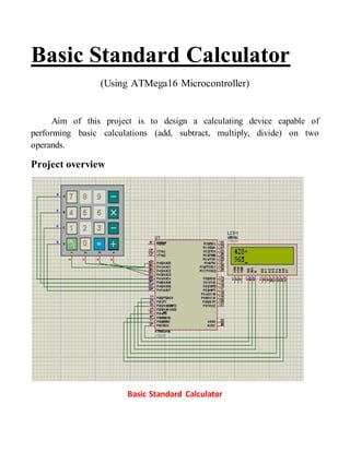
(Using ATMega16 Microcontroller) 
Aim of this project is to design a calculating device capable of 
performing basic calculations (add, subtract, multiply, divide) on two 
operands. 
Project overview 
Basic Standard Calculator
Hardware components required 
1. ATMega 16 microcontroller 
2. Basic calculator keypad 
3. 2x16 LCD 
Keypad and LCD are connected with microcontroller to make an easy man-machine 
interface to make the calculator capable of performing the desired 
function. 
 ATMega16 microcontroller: This is the brain of system which is 
programmed to take input from user through keypad, perform the 
desired operation and then display the result on the provided 2x16 LCD. 
 Basic calculator keypad: This is a 4x4 (having 4 rows and 4 columns) 
keypad which is interfaced with microcontroller with its each key 
assigned a specific no. or operator defined in the program. 
 2x16 LCD: this is the liquid crystal display module capable of 
displaying 32 characters in two rows (16 in each row). Microcontroller 
displays characters on it while taking inputs from user and to display the 
result to user.
Interfacing keypad with microcontroller 
Keyboard Connections to PORTS 
With matrix keypads 16 keys can function with 8 pins (4 rows and 4 columns) 
of microcontroller’s either same or different ports as convenient.
Scanning and identifying the key pressed
Function to identify a key pressed 
//connect colum with lower nibble and rows with upper nibble 
#define key_port PORTA 
#define key_ddr DDRA 
#define key_pin PINA 
unsigned char keypad[4][4]={'7','8','9','/', 
'4','5','6','*', 
'1','2','3','-', 
'c','0','=','+'}; 
char takekey() 
{ 
unsigned char row,colum; 
char key; 
key_ddr=0xf0; 
key_port=0xff; 
do 
{ 
key_port&=0x0f; 
colum=(key_pin&0x0f); 
}while(colum!=0x0f); 
do 
{ 
do 
{ 
_delay_ms(1); 
key_port&=0x0f; 
colum=(key_pin&0x0f); 
}while(colum==0x0f); 
_delay_ms(1); 
key_port&=0x0f;
colum=(key_pin&0x0f); 
}while(colum==0x0f); 
while(1) 
{ 
key_port=0xef; 
colum=(key_pin&0x0f); 
if(colum!=0x0f) 
{ 
row=0; 
break; 
} 
key_port=0xdf; 
colum=(key_pin&0x0f); 
if(colum!=0x0f) 
{ 
row=1; 
break; 
} 
key_port=0xbf; 
colum=(key_pin&0x0f); 
if(colum!=0x0f) 
{ 
row=2; 
break; 
} 
key_port=0x7f; 
colum=(key_pin&0x0f); 
row=3; 
break; 
}
if(colum==0x0e) 
key=keypad[row][0]; 
else if(colum==0x0d) 
key=keypad[row][1]; 
else if(colum==0x0b) 
key=keypad[row][2]; 
else 
key=keypad[row][3]; 
return(key); 
} 
Interfacing 2x16 LCD with microcontroller (in 4 bit mode) 
LCD interfacing with atmega 16
LCD functions in accordance with above figure: 
#define en PA2 // enable signal 
#define rw PA1 // read/write signal 
#define rs PA0 // register select signal 
void lcd_cmd(unsigned char cmd) 
{ 
DDRA=0xff; 
PORTA=0; 
PORTA=cmd&0xf0; 
lcd &=~(1<<rs); 
lcd &=~(1<<rw); 
lcd |= (1<<en); 
_delay_ms(1); 
lcd &=~(1<<en); 
_delay_ms(1); 
PORTA=((cmd<<4)&0xf0); 
lcd &=~(1<<rs); 
lcd &=~(1<<rw); 
lcd |= (1<<en); 
_delay_ms(1); 
lcd &=~(1<<en); 
_delay_ms(1); 
return; 
} 
void lcd_data(unsigned char data) 
{ 
PORTA=(data&0xf0); 
lcd |=(1<<rs); 
lcd &=~(1<<rw); 
lcd |= (1<<en);
_delay_ms(1); 
lcd &=~(1<<en); 
_delay_ms(1); // delay to get things executed 
PORTA= ((data<<4)&0xf0); 
lcd |=(1<<rs); 
lcd &=~(1<<rw); 
lcd |= (1<<en); 
_delay_ms(1); 
lcd &=~(1<<en); 
return ; 
} 
void ini_lcd(void) 
{ 
_delay_ms(5); 
lcd_cmd(0x02); 
_delay_ms(1); 
lcd_cmd(0x28); 
_delay_ms(1); 
lcd_cmd(0x01); // clear LCD 
_delay_ms(1); 
lcd_cmd(0x0E); // cursor ON 
_delay_ms(1); 
lcd_cmd(0x84); 
_delay_ms(1); 
return; 
}
Calculator 
The functioning of calculator s as follows: 
i. Enter first operand 
ii. Enter operator 
iii. Enter second operand 
iv. Press result key 
Main program: 
#include<avr/io.h> 
#include<util/delay.h> 
#include"4bitlcd.h" 
#include"keypad.h" 
#define key_port PORTA 
#define key_ddr DDRA 
#define key_pin PINA 
void lcd_cmd(unsigned char cmd); 
void lcd_data(unsigned char data); 
void ini_lcd(void); 
void main() 
{ 
unsigned char ch=0,op=0; 
long o1=0,o2=0,o3=0,ch1=0; 
PORTB=0XFF; 
DDRB=0xff; 
_delay_ms(5); 
ini_lcd(); 
while(1) 
{
lcd_data('k'); 
lcd_cmd(0x01); 
_delay_ms(20); 
ch=0; 
op=0; 
ch1=0; 
o1=0; 
o2=0; 
o3=0; 
lcd_cmd(0x80); 
while((ch!='+')&(ch!='-')&(ch!='*')&(ch!='/')) //get first operand and operator 
{ 
ch=takekey(); 
ch1=ch; 
if((ch!='c')&(ch!='=')&(ch!='+')&(ch!='-')&(ch!='*')&(ch!='/')) 
{ 
lcd_data(ch); 
o1=((o1*10)+(ch1-0x30)); 
} 
else 
{ 
op=ch; 
lcd_data(ch); 
break; 
} 
} 
ch=0; 
ch1=0; 
lcd_cmd(0xc0); 
while((ch!='+')&(ch!='-')&(ch!='*')&(ch!='/')) //get second operand
{ 
ch=takekey(); 
ch1=ch; 
if((ch!='c')&(ch!='=')&(ch!='+')&(ch!='-')&(ch!='*')&(ch!='/')) 
{ 
lcd_data(ch); 
o2=((o2*10)+(ch1-0x30)); 
} 
else 
{ 
lcd_cmd(0x01); 
break; 
} 
} 
switch(op) //apply operation 
{ 
case '+': 
o3=o1+o2; 
lcd_data('a'); 
_delay_ms(5); 
break; 
case '-': 
o3=o1-o2; 
lcd_data('s'); 
_delay_ms(5); 
break; 
case '*': 
o3=o1*o2;
lcd_data('m'); 
_delay_ms(5); 
break; 
case '/': 
o3=o1/o2; 
lcd_data('d'); 
_delay_ms(5); 
break; 
default: 
lcd_cmd(0x01); 
_delay_ms(5); 
} 
lcd_cmd(0xc2); 
lcd_cmd(0x01); 
lcd_cmd(0xce); 
while(o3) //print result 
{ 
lcd_data((o3%10)+0x30); 
lcd_cmd(0x10); 
lcd_cmd(0x10); 
o3=o3/10; 
} 
ch=takekey(); 
lcd_cmd(0x01); 
_delay_ms(5); 
} 
return ; 
}

Más contenido relacionado

La actualidad más candente

Programmable Logic Devices
Programmable Logic DevicesProgrammable Logic Devices
Programmable Logic DevicesMadhusudan Donga
 
Combinational Circuits
Combinational CircuitsCombinational Circuits
Combinational CircuitsDilum Bandara
 
ARM stacks, subroutines, Cortex M3, LPC 214X
ARM  stacks, subroutines, Cortex M3, LPC 214XARM  stacks, subroutines, Cortex M3, LPC 214X
ARM stacks, subroutines, Cortex M3, LPC 214XKarthik Vivek
 
Basics of arduino uno
Basics of arduino unoBasics of arduino uno
Basics of arduino unoRahat Sood
 
PIR sensing with arduino
PIR sensing  with  arduinoPIR sensing  with  arduino
PIR sensing with arduinochetan kadiwal
 
microcontroller vs microprocessor
microcontroller vs microprocessormicrocontroller vs microprocessor
microcontroller vs microprocessorsobhadevi
 
CAN interfacing on LPC1768 (ARM Cortex M3 based Micro controller)
CAN interfacing on LPC1768 (ARM Cortex M3 based Micro controller)CAN interfacing on LPC1768 (ARM Cortex M3 based Micro controller)
CAN interfacing on LPC1768 (ARM Cortex M3 based Micro controller)Omkar Rane
 
Industrial training report of embedded system and robotics
Industrial training report of embedded system and roboticsIndustrial training report of embedded system and robotics
Industrial training report of embedded system and roboticsPallavi Bharti
 
Keypad Interfacing with 8051 Microcontroller
Keypad Interfacing with 8051 MicrocontrollerKeypad Interfacing with 8051 Microcontroller
Keypad Interfacing with 8051 MicrocontrollerSudhanshu Janwadkar
 
Applications of microprocessor
Applications of microprocessorApplications of microprocessor
Applications of microprocessorAnjali Agrawal
 
Computer architecture control unit
Computer architecture control unitComputer architecture control unit
Computer architecture control unitMazin Alwaaly
 
Subroutine in 8051 microcontroller
Subroutine in 8051 microcontrollerSubroutine in 8051 microcontroller
Subroutine in 8051 microcontrollerbhadresh savani
 

La actualidad más candente (20)

Programmable Logic Devices
Programmable Logic DevicesProgrammable Logic Devices
Programmable Logic Devices
 
Embedded System Basics
Embedded System BasicsEmbedded System Basics
Embedded System Basics
 
Vhdl programming
Vhdl programmingVhdl programming
Vhdl programming
 
Chapter 7 1
Chapter 7 1Chapter 7 1
Chapter 7 1
 
Unit vi (2)
Unit vi (2)Unit vi (2)
Unit vi (2)
 
MULTIPLEXER
MULTIPLEXERMULTIPLEXER
MULTIPLEXER
 
Arduino Projects
Arduino ProjectsArduino Projects
Arduino Projects
 
Combinational Circuits
Combinational CircuitsCombinational Circuits
Combinational Circuits
 
Microcontroller 8051
Microcontroller 8051Microcontroller 8051
Microcontroller 8051
 
ARM stacks, subroutines, Cortex M3, LPC 214X
ARM  stacks, subroutines, Cortex M3, LPC 214XARM  stacks, subroutines, Cortex M3, LPC 214X
ARM stacks, subroutines, Cortex M3, LPC 214X
 
Basics of arduino uno
Basics of arduino unoBasics of arduino uno
Basics of arduino uno
 
PIR sensing with arduino
PIR sensing  with  arduinoPIR sensing  with  arduino
PIR sensing with arduino
 
microcontroller vs microprocessor
microcontroller vs microprocessormicrocontroller vs microprocessor
microcontroller vs microprocessor
 
CAN interfacing on LPC1768 (ARM Cortex M3 based Micro controller)
CAN interfacing on LPC1768 (ARM Cortex M3 based Micro controller)CAN interfacing on LPC1768 (ARM Cortex M3 based Micro controller)
CAN interfacing on LPC1768 (ARM Cortex M3 based Micro controller)
 
Industrial training report of embedded system and robotics
Industrial training report of embedded system and roboticsIndustrial training report of embedded system and robotics
Industrial training report of embedded system and robotics
 
Keypad Interfacing with 8051 Microcontroller
Keypad Interfacing with 8051 MicrocontrollerKeypad Interfacing with 8051 Microcontroller
Keypad Interfacing with 8051 Microcontroller
 
Applications of microprocessor
Applications of microprocessorApplications of microprocessor
Applications of microprocessor
 
Buzzer
BuzzerBuzzer
Buzzer
 
Computer architecture control unit
Computer architecture control unitComputer architecture control unit
Computer architecture control unit
 
Subroutine in 8051 microcontroller
Subroutine in 8051 microcontrollerSubroutine in 8051 microcontroller
Subroutine in 8051 microcontroller
 

Similar a Basic standard calculator

Automatic room light controller with visible counter
Automatic room light controller with visible counterAutomatic room light controller with visible counter
Automatic room light controller with visible counterMafaz Ahmed
 
SIMPLE Frequency METER using AT89c51
SIMPLE Frequency METER using AT89c51 SIMPLE Frequency METER using AT89c51
SIMPLE Frequency METER using AT89c51 aroosa khan
 
2022-BEKM 3453 - LCD and keypad.pdf
2022-BEKM 3453 - LCD and keypad.pdf2022-BEKM 3453 - LCD and keypad.pdf
2022-BEKM 3453 - LCD and keypad.pdfVNEX
 
Customizable Microprocessor design on Nexys 3 Spartan FPGA Board
Customizable Microprocessor design on Nexys 3 Spartan FPGA BoardCustomizable Microprocessor design on Nexys 3 Spartan FPGA Board
Customizable Microprocessor design on Nexys 3 Spartan FPGA BoardBharat Biyani
 
Keypad interfacing 8051 -NANOCDAC
Keypad interfacing 8051 -NANOCDACKeypad interfacing 8051 -NANOCDAC
Keypad interfacing 8051 -NANOCDACnanocdac
 
Functions for Nano 5 Card
Functions for Nano 5 CardFunctions for Nano 5 Card
Functions for Nano 5 CardOmar Sanchez
 
m.tech esd lab manual for record
m.tech esd lab manual for recordm.tech esd lab manual for record
m.tech esd lab manual for recordG Lemuel George
 
Combine the keypad and LCD codes in compliance to the following requ.pdf
Combine the keypad and LCD codes in compliance to the following requ.pdfCombine the keypad and LCD codes in compliance to the following requ.pdf
Combine the keypad and LCD codes in compliance to the following requ.pdfforwardcom41
 
The functional design scheme of the dedicated keyboard chip kb core based on ...
The functional design scheme of the dedicated keyboard chip kb core based on ...The functional design scheme of the dedicated keyboard chip kb core based on ...
The functional design scheme of the dedicated keyboard chip kb core based on ...Vinsion Chan
 
Data Acquisition
Data AcquisitionData Acquisition
Data Acquisitionazhar557
 

Similar a Basic standard calculator (20)

Password based door locksystem
Password  based door locksystemPassword  based door locksystem
Password based door locksystem
 
131080111003 mci
131080111003 mci131080111003 mci
131080111003 mci
 
Automatic room light controller with visible counter
Automatic room light controller with visible counterAutomatic room light controller with visible counter
Automatic room light controller with visible counter
 
SIMPLE Frequency METER using AT89c51
SIMPLE Frequency METER using AT89c51 SIMPLE Frequency METER using AT89c51
SIMPLE Frequency METER using AT89c51
 
Lcd & keypad
Lcd & keypadLcd & keypad
Lcd & keypad
 
LCD_Example.pptx
LCD_Example.pptxLCD_Example.pptx
LCD_Example.pptx
 
2022-BEKM 3453 - LCD and keypad.pdf
2022-BEKM 3453 - LCD and keypad.pdf2022-BEKM 3453 - LCD and keypad.pdf
2022-BEKM 3453 - LCD and keypad.pdf
 
ESD -DAY 24.pptx
ESD -DAY 24.pptxESD -DAY 24.pptx
ESD -DAY 24.pptx
 
Unit1 C
Unit1 CUnit1 C
Unit1 C
 
Unit1 C
Unit1 CUnit1 C
Unit1 C
 
Customizable Microprocessor design on Nexys 3 Spartan FPGA Board
Customizable Microprocessor design on Nexys 3 Spartan FPGA BoardCustomizable Microprocessor design on Nexys 3 Spartan FPGA Board
Customizable Microprocessor design on Nexys 3 Spartan FPGA Board
 
Keypad interfacing 8051 -NANOCDAC
Keypad interfacing 8051 -NANOCDACKeypad interfacing 8051 -NANOCDAC
Keypad interfacing 8051 -NANOCDAC
 
Functions for Nano 5 Card
Functions for Nano 5 CardFunctions for Nano 5 Card
Functions for Nano 5 Card
 
m.tech esd lab manual for record
m.tech esd lab manual for recordm.tech esd lab manual for record
m.tech esd lab manual for record
 
Combine the keypad and LCD codes in compliance to the following requ.pdf
Combine the keypad and LCD codes in compliance to the following requ.pdfCombine the keypad and LCD codes in compliance to the following requ.pdf
Combine the keypad and LCD codes in compliance to the following requ.pdf
 
The functional design scheme of the dedicated keyboard chip kb core based on ...
The functional design scheme of the dedicated keyboard chip kb core based on ...The functional design scheme of the dedicated keyboard chip kb core based on ...
The functional design scheme of the dedicated keyboard chip kb core based on ...
 
Data Acquisition
Data AcquisitionData Acquisition
Data Acquisition
 
Experiment 16 x2 parallel lcd
Experiment   16 x2 parallel lcdExperiment   16 x2 parallel lcd
Experiment 16 x2 parallel lcd
 
PIC and LCD
PIC and LCDPIC and LCD
PIC and LCD
 
Switch Control and Time Delay - Keypad
Switch Control and Time Delay - KeypadSwitch Control and Time Delay - Keypad
Switch Control and Time Delay - Keypad
 

Más de UVSofts Technologies (16)

Arduino dtmf controlled robot
Arduino dtmf controlled robotArduino dtmf controlled robot
Arduino dtmf controlled robot
 
Arduino bluetooth controlled robot
Arduino bluetooth controlled robotArduino bluetooth controlled robot
Arduino bluetooth controlled robot
 
Vehicle tracting system
Vehicle tracting systemVehicle tracting system
Vehicle tracting system
 
GPS based tracking system
GPS based tracking systemGPS based tracking system
GPS based tracking system
 
Password based door locksystem
Password  based door locksystemPassword  based door locksystem
Password based door locksystem
 
Calculator
CalculatorCalculator
Calculator
 
Bluetooth controlled robot
Bluetooth controlled robotBluetooth controlled robot
Bluetooth controlled robot
 
Pc controlled robot
Pc controlled robotPc controlled robot
Pc controlled robot
 
Bluetooth controlled robot
Bluetooth controlled robotBluetooth controlled robot
Bluetooth controlled robot
 
Pc controlled robot
Pc controlled robotPc controlled robot
Pc controlled robot
 
Mobile controll robot
Mobile controll robotMobile controll robot
Mobile controll robot
 
Mobile controlled robot
Mobile controlled robotMobile controlled robot
Mobile controlled robot
 
Edge detector robot
Edge detector robotEdge detector robot
Edge detector robot
 
Line follower robot
Line follower robotLine follower robot
Line follower robot
 
Line follower robot
Line follower robotLine follower robot
Line follower robot
 
Edge detector & avoider robot
Edge detector & avoider robotEdge detector & avoider robot
Edge detector & avoider robot
 

Último

Double Revolving field theory-how the rotor develops torque
Double Revolving field theory-how the rotor develops torqueDouble Revolving field theory-how the rotor develops torque
Double Revolving field theory-how the rotor develops torqueBhangaleSonal
 
Online food ordering system project report.pdf
Online food ordering system project report.pdfOnline food ordering system project report.pdf
Online food ordering system project report.pdfKamal Acharya
 
HOA1&2 - Module 3 - PREHISTORCI ARCHITECTURE OF KERALA.pptx
HOA1&2 - Module 3 - PREHISTORCI ARCHITECTURE OF KERALA.pptxHOA1&2 - Module 3 - PREHISTORCI ARCHITECTURE OF KERALA.pptx
HOA1&2 - Module 3 - PREHISTORCI ARCHITECTURE OF KERALA.pptxSCMS School of Architecture
 
AIRCANVAS[1].pdf mini project for btech students
AIRCANVAS[1].pdf mini project for btech studentsAIRCANVAS[1].pdf mini project for btech students
AIRCANVAS[1].pdf mini project for btech studentsvanyagupta248
 
Wadi Rum luxhotel lodge Analysis case study.pptx
Wadi Rum luxhotel lodge Analysis case study.pptxWadi Rum luxhotel lodge Analysis case study.pptx
Wadi Rum luxhotel lodge Analysis case study.pptxNadaHaitham1
 
GEAR TRAIN- BASIC CONCEPTS AND WORKING PRINCIPLE
GEAR TRAIN- BASIC CONCEPTS AND WORKING PRINCIPLEGEAR TRAIN- BASIC CONCEPTS AND WORKING PRINCIPLE
GEAR TRAIN- BASIC CONCEPTS AND WORKING PRINCIPLEselvakumar948
 
Unleashing the Power of the SORA AI lastest leap
Unleashing the Power of the SORA AI lastest leapUnleashing the Power of the SORA AI lastest leap
Unleashing the Power of the SORA AI lastest leapRishantSharmaFr
 
COST-EFFETIVE and Energy Efficient BUILDINGS ptx
COST-EFFETIVE  and Energy Efficient BUILDINGS ptxCOST-EFFETIVE  and Energy Efficient BUILDINGS ptx
COST-EFFETIVE and Energy Efficient BUILDINGS ptxJIT KUMAR GUPTA
 
Online electricity billing project report..pdf
Online electricity billing project report..pdfOnline electricity billing project report..pdf
Online electricity billing project report..pdfKamal Acharya
 
Introduction to Serverless with AWS Lambda
Introduction to Serverless with AWS LambdaIntroduction to Serverless with AWS Lambda
Introduction to Serverless with AWS LambdaOmar Fathy
 
Verification of thevenin's theorem for BEEE Lab (1).pptx
Verification of thevenin's theorem for BEEE Lab (1).pptxVerification of thevenin's theorem for BEEE Lab (1).pptx
Verification of thevenin's theorem for BEEE Lab (1).pptxchumtiyababu
 
Employee leave management system project.
Employee leave management system project.Employee leave management system project.
Employee leave management system project.Kamal Acharya
 
Engineering Drawing focus on projection of planes
Engineering Drawing focus on projection of planesEngineering Drawing focus on projection of planes
Engineering Drawing focus on projection of planesRAJNEESHKUMAR341697
 
Unit 4_Part 1 CSE2001 Exception Handling and Function Template and Class Temp...
Unit 4_Part 1 CSE2001 Exception Handling and Function Template and Class Temp...Unit 4_Part 1 CSE2001 Exception Handling and Function Template and Class Temp...
Unit 4_Part 1 CSE2001 Exception Handling and Function Template and Class Temp...drmkjayanthikannan
 
DC MACHINE-Motoring and generation, Armature circuit equation
DC MACHINE-Motoring and generation, Armature circuit equationDC MACHINE-Motoring and generation, Armature circuit equation
DC MACHINE-Motoring and generation, Armature circuit equationBhangaleSonal
 
Thermal Engineering -unit - III & IV.ppt
Thermal Engineering -unit - III & IV.pptThermal Engineering -unit - III & IV.ppt
Thermal Engineering -unit - III & IV.pptDineshKumar4165
 
PE 459 LECTURE 2- natural gas basic concepts and properties
PE 459 LECTURE 2- natural gas basic concepts and propertiesPE 459 LECTURE 2- natural gas basic concepts and properties
PE 459 LECTURE 2- natural gas basic concepts and propertiessarkmank1
 
Thermal Engineering-R & A / C - unit - V
Thermal Engineering-R & A / C - unit - VThermal Engineering-R & A / C - unit - V
Thermal Engineering-R & A / C - unit - VDineshKumar4165
 

Último (20)

Double Revolving field theory-how the rotor develops torque
Double Revolving field theory-how the rotor develops torqueDouble Revolving field theory-how the rotor develops torque
Double Revolving field theory-how the rotor develops torque
 
Online food ordering system project report.pdf
Online food ordering system project report.pdfOnline food ordering system project report.pdf
Online food ordering system project report.pdf
 
HOA1&2 - Module 3 - PREHISTORCI ARCHITECTURE OF KERALA.pptx
HOA1&2 - Module 3 - PREHISTORCI ARCHITECTURE OF KERALA.pptxHOA1&2 - Module 3 - PREHISTORCI ARCHITECTURE OF KERALA.pptx
HOA1&2 - Module 3 - PREHISTORCI ARCHITECTURE OF KERALA.pptx
 
AIRCANVAS[1].pdf mini project for btech students
AIRCANVAS[1].pdf mini project for btech studentsAIRCANVAS[1].pdf mini project for btech students
AIRCANVAS[1].pdf mini project for btech students
 
FEA Based Level 3 Assessment of Deformed Tanks with Fluid Induced Loads
FEA Based Level 3 Assessment of Deformed Tanks with Fluid Induced LoadsFEA Based Level 3 Assessment of Deformed Tanks with Fluid Induced Loads
FEA Based Level 3 Assessment of Deformed Tanks with Fluid Induced Loads
 
Wadi Rum luxhotel lodge Analysis case study.pptx
Wadi Rum luxhotel lodge Analysis case study.pptxWadi Rum luxhotel lodge Analysis case study.pptx
Wadi Rum luxhotel lodge Analysis case study.pptx
 
GEAR TRAIN- BASIC CONCEPTS AND WORKING PRINCIPLE
GEAR TRAIN- BASIC CONCEPTS AND WORKING PRINCIPLEGEAR TRAIN- BASIC CONCEPTS AND WORKING PRINCIPLE
GEAR TRAIN- BASIC CONCEPTS AND WORKING PRINCIPLE
 
Unleashing the Power of the SORA AI lastest leap
Unleashing the Power of the SORA AI lastest leapUnleashing the Power of the SORA AI lastest leap
Unleashing the Power of the SORA AI lastest leap
 
COST-EFFETIVE and Energy Efficient BUILDINGS ptx
COST-EFFETIVE  and Energy Efficient BUILDINGS ptxCOST-EFFETIVE  and Energy Efficient BUILDINGS ptx
COST-EFFETIVE and Energy Efficient BUILDINGS ptx
 
Online electricity billing project report..pdf
Online electricity billing project report..pdfOnline electricity billing project report..pdf
Online electricity billing project report..pdf
 
Introduction to Serverless with AWS Lambda
Introduction to Serverless with AWS LambdaIntroduction to Serverless with AWS Lambda
Introduction to Serverless with AWS Lambda
 
Verification of thevenin's theorem for BEEE Lab (1).pptx
Verification of thevenin's theorem for BEEE Lab (1).pptxVerification of thevenin's theorem for BEEE Lab (1).pptx
Verification of thevenin's theorem for BEEE Lab (1).pptx
 
Employee leave management system project.
Employee leave management system project.Employee leave management system project.
Employee leave management system project.
 
Cara Menggugurkan Sperma Yang Masuk Rahim Biyar Tidak Hamil
Cara Menggugurkan Sperma Yang Masuk Rahim Biyar Tidak HamilCara Menggugurkan Sperma Yang Masuk Rahim Biyar Tidak Hamil
Cara Menggugurkan Sperma Yang Masuk Rahim Biyar Tidak Hamil
 
Engineering Drawing focus on projection of planes
Engineering Drawing focus on projection of planesEngineering Drawing focus on projection of planes
Engineering Drawing focus on projection of planes
 
Unit 4_Part 1 CSE2001 Exception Handling and Function Template and Class Temp...
Unit 4_Part 1 CSE2001 Exception Handling and Function Template and Class Temp...Unit 4_Part 1 CSE2001 Exception Handling and Function Template and Class Temp...
Unit 4_Part 1 CSE2001 Exception Handling and Function Template and Class Temp...
 
DC MACHINE-Motoring and generation, Armature circuit equation
DC MACHINE-Motoring and generation, Armature circuit equationDC MACHINE-Motoring and generation, Armature circuit equation
DC MACHINE-Motoring and generation, Armature circuit equation
 
Thermal Engineering -unit - III & IV.ppt
Thermal Engineering -unit - III & IV.pptThermal Engineering -unit - III & IV.ppt
Thermal Engineering -unit - III & IV.ppt
 
PE 459 LECTURE 2- natural gas basic concepts and properties
PE 459 LECTURE 2- natural gas basic concepts and propertiesPE 459 LECTURE 2- natural gas basic concepts and properties
PE 459 LECTURE 2- natural gas basic concepts and properties
 
Thermal Engineering-R & A / C - unit - V
Thermal Engineering-R & A / C - unit - VThermal Engineering-R & A / C - unit - V
Thermal Engineering-R & A / C - unit - V
 

Basic standard calculator

  • 1. Basic Standard Calculator (Using ATMega16 Microcontroller) Aim of this project is to design a calculating device capable of performing basic calculations (add, subtract, multiply, divide) on two operands. Project overview Basic Standard Calculator
  • 2. Hardware components required 1. ATMega 16 microcontroller 2. Basic calculator keypad 3. 2x16 LCD Keypad and LCD are connected with microcontroller to make an easy man-machine interface to make the calculator capable of performing the desired function.  ATMega16 microcontroller: This is the brain of system which is programmed to take input from user through keypad, perform the desired operation and then display the result on the provided 2x16 LCD.  Basic calculator keypad: This is a 4x4 (having 4 rows and 4 columns) keypad which is interfaced with microcontroller with its each key assigned a specific no. or operator defined in the program.  2x16 LCD: this is the liquid crystal display module capable of displaying 32 characters in two rows (16 in each row). Microcontroller displays characters on it while taking inputs from user and to display the result to user.
  • 3. Interfacing keypad with microcontroller Keyboard Connections to PORTS With matrix keypads 16 keys can function with 8 pins (4 rows and 4 columns) of microcontroller’s either same or different ports as convenient.
  • 4. Scanning and identifying the key pressed
  • 5. Function to identify a key pressed //connect colum with lower nibble and rows with upper nibble #define key_port PORTA #define key_ddr DDRA #define key_pin PINA unsigned char keypad[4][4]={'7','8','9','/', '4','5','6','*', '1','2','3','-', 'c','0','=','+'}; char takekey() { unsigned char row,colum; char key; key_ddr=0xf0; key_port=0xff; do { key_port&=0x0f; colum=(key_pin&0x0f); }while(colum!=0x0f); do { do { _delay_ms(1); key_port&=0x0f; colum=(key_pin&0x0f); }while(colum==0x0f); _delay_ms(1); key_port&=0x0f;
  • 6. colum=(key_pin&0x0f); }while(colum==0x0f); while(1) { key_port=0xef; colum=(key_pin&0x0f); if(colum!=0x0f) { row=0; break; } key_port=0xdf; colum=(key_pin&0x0f); if(colum!=0x0f) { row=1; break; } key_port=0xbf; colum=(key_pin&0x0f); if(colum!=0x0f) { row=2; break; } key_port=0x7f; colum=(key_pin&0x0f); row=3; break; }
  • 7. if(colum==0x0e) key=keypad[row][0]; else if(colum==0x0d) key=keypad[row][1]; else if(colum==0x0b) key=keypad[row][2]; else key=keypad[row][3]; return(key); } Interfacing 2x16 LCD with microcontroller (in 4 bit mode) LCD interfacing with atmega 16
  • 8. LCD functions in accordance with above figure: #define en PA2 // enable signal #define rw PA1 // read/write signal #define rs PA0 // register select signal void lcd_cmd(unsigned char cmd) { DDRA=0xff; PORTA=0; PORTA=cmd&0xf0; lcd &=~(1<<rs); lcd &=~(1<<rw); lcd |= (1<<en); _delay_ms(1); lcd &=~(1<<en); _delay_ms(1); PORTA=((cmd<<4)&0xf0); lcd &=~(1<<rs); lcd &=~(1<<rw); lcd |= (1<<en); _delay_ms(1); lcd &=~(1<<en); _delay_ms(1); return; } void lcd_data(unsigned char data) { PORTA=(data&0xf0); lcd |=(1<<rs); lcd &=~(1<<rw); lcd |= (1<<en);
  • 9. _delay_ms(1); lcd &=~(1<<en); _delay_ms(1); // delay to get things executed PORTA= ((data<<4)&0xf0); lcd |=(1<<rs); lcd &=~(1<<rw); lcd |= (1<<en); _delay_ms(1); lcd &=~(1<<en); return ; } void ini_lcd(void) { _delay_ms(5); lcd_cmd(0x02); _delay_ms(1); lcd_cmd(0x28); _delay_ms(1); lcd_cmd(0x01); // clear LCD _delay_ms(1); lcd_cmd(0x0E); // cursor ON _delay_ms(1); lcd_cmd(0x84); _delay_ms(1); return; }
  • 10. Calculator The functioning of calculator s as follows: i. Enter first operand ii. Enter operator iii. Enter second operand iv. Press result key Main program: #include<avr/io.h> #include<util/delay.h> #include"4bitlcd.h" #include"keypad.h" #define key_port PORTA #define key_ddr DDRA #define key_pin PINA void lcd_cmd(unsigned char cmd); void lcd_data(unsigned char data); void ini_lcd(void); void main() { unsigned char ch=0,op=0; long o1=0,o2=0,o3=0,ch1=0; PORTB=0XFF; DDRB=0xff; _delay_ms(5); ini_lcd(); while(1) {
  • 11. lcd_data('k'); lcd_cmd(0x01); _delay_ms(20); ch=0; op=0; ch1=0; o1=0; o2=0; o3=0; lcd_cmd(0x80); while((ch!='+')&(ch!='-')&(ch!='*')&(ch!='/')) //get first operand and operator { ch=takekey(); ch1=ch; if((ch!='c')&(ch!='=')&(ch!='+')&(ch!='-')&(ch!='*')&(ch!='/')) { lcd_data(ch); o1=((o1*10)+(ch1-0x30)); } else { op=ch; lcd_data(ch); break; } } ch=0; ch1=0; lcd_cmd(0xc0); while((ch!='+')&(ch!='-')&(ch!='*')&(ch!='/')) //get second operand
  • 12. { ch=takekey(); ch1=ch; if((ch!='c')&(ch!='=')&(ch!='+')&(ch!='-')&(ch!='*')&(ch!='/')) { lcd_data(ch); o2=((o2*10)+(ch1-0x30)); } else { lcd_cmd(0x01); break; } } switch(op) //apply operation { case '+': o3=o1+o2; lcd_data('a'); _delay_ms(5); break; case '-': o3=o1-o2; lcd_data('s'); _delay_ms(5); break; case '*': o3=o1*o2;
  • 13. lcd_data('m'); _delay_ms(5); break; case '/': o3=o1/o2; lcd_data('d'); _delay_ms(5); break; default: lcd_cmd(0x01); _delay_ms(5); } lcd_cmd(0xc2); lcd_cmd(0x01); lcd_cmd(0xce); while(o3) //print result { lcd_data((o3%10)+0x30); lcd_cmd(0x10); lcd_cmd(0x10); o3=o3/10; } ch=takekey(); lcd_cmd(0x01); _delay_ms(5); } return ; }