SlideShare una empresa de Scribd logo
1 de 17
QUAID-E-AWAM UNIVERSITY OF ENGINEERING SCIENCE & TECHNOLOGY
                                      NAWABSHAH

               DEPARTMENT OF INFORMATION TECHNOLOGY

Digital Logic & Computer Architects                     (3rd Term, 2nd Year)

                                             PRACTICAL # 01

      OBJECTIVE: To Become Familiar With Basic Binary Operation.

      TOOL: Electronic Work Bench V 5.12

      EQUIPMENT AND COMPONENTS:

              Logic Gates
              Indicator (LED)
              Two Switches
              Ground
              Voltage Source


      AND Gate:

      Logic Expression:                A.B= Y


      Logic Symbol:


      Truth Table:
                                        INPUTS                  OUTPUT
                                   A               B                 Y
                                   0               0                 0
                                   0               1                 0
                                   1               0                 0
                                   1               1                 1
      Explanation:
                       The AND gate is a logic device whose output is 1 if and only if all its inputs
      are 1. In other words the output of an AND gate is 0 if any one or both its inputs are 0. It can
      have two or more inputs can only one output.
      It is also called an all or nothing gate, because it produces a 1 only in one case when all its
      inputs are a 1. In all other cases its output is zero.
QUAID-E-AWAM UNIVERSITY OF ENGINEERING SCIENCE & TECHNOLOGY
                                   NAWABSHAH

              DEPARTMENT OF INFORMATION TECHNOLOGY

Digital Logic & Computer Architects                     (3rd Term, 2nd Year)

                                             PRACTICAL # 01


      OR Gate:


      Logic Expression:                A+B= Y


      Logic Symbol:


      Truth Table:
                                        INPUTS                   OUTPUT
                                   A               B                   Y
                                   0               0                   0
                                   0               1                   1
                                   1               0                   1
                                   1               1                   1


      Explanation:
                      The OR gate is a logic device whose output is 1 if at least one if its input is 1.
      In other words the output of an OR gate is 0 if both its inputs are 0.
      It is also called any or all gate, because it produces a 1 even if one of its inputs is at 1.
      It produces a 0 only when all the inputs are 0.
Viva Question:

Q: 1 why we use logic Gates?
Ans: Logic gates are used to make logic circuits.


Q: 2 Advantages of logic gates?
Ans: Logic gates are basic components of microprocessors. Without them, electronics
systems couldn't run.


Q: 3 what is also called NOT gate?
Ans: The NOT gate also called INVERTER.


Q: 4 Where output of AND Gate is high and low?
Ans: If both inputs are high the output will be high/true/on else output of AND gate is
low/false/off.
QUAID-E-AWAM UNIVERSITY OF ENGINEERING SCIENCE & TECHNOLOGY
                                     NAWABSHAH

              DEPARTMENT OF INFORMATION TECHNOLOGY

Digital Logic & Computer Architects                  (3rd Term, 2nd Year)

                                          PRACTICAL # 02

      OBJECTIVE: To implement and verify the NOR gate, NAND gate operations.

      TOOL: Electronic Work Bench V 5.12

      EQUIPMENT AND COMPONENTS:

             Logic Gates
             Indicator (LED)
             Two Switches
             Ground
             Voltage Source


      NOR Gate:

      Logic Expression:              ( A + B)¯ = Y


      Logic Symbol:


      Truth Table:
                                      INPUTS                  OUTPUT
                                 A              B                   Y
                                 0              0                   1
                                 0              1                   0
                                 1              0                   0
                                 1              1                   0


      Explanation:


                     The NOR gate is a device whose out is 1 if and only if all inputs are at 0. In all
      other cases the output is 0. The name NOR is derived from NOT-OR, because the gate
      performs the same logic as OR gate followed by an inverter. It is a universal gate. It can also
      be used as an inverter.
QUAID-E-AWAM UNIVERSITY OF ENGINEERING SCIENCE & TECHNOLOGY
                                                   NAWABSHAH


              DEPARTMENT OF INFORMATION TECHNOLOGY

Digital Logic & Computer Architects                    (3rd Term, 2nd Year)


                                         PRACTICAL # 02

      NAND Gate:

      Logic Expression:               ( A . B)¯ = Y


      Logic Symbol:


      Truth Table:
                                       INPUTS                  OUTPUT
                                  A              B                   Y
                                  0              0                   1
                                  0              1                   1
                                  1              0                   1
                                  1              1                   0


      Explanation:
                     The NAND gate is a device whose output is 1 if at least one of its inputs is 0.
      Thus the output is 0 when all its inputs are 1. The name NAND is derived from NOT-AND
      because the gate performs the same logic as AND gate followed by an inverter. It is a
      universal gate as all basic gates can be derived from it. It can also be used as an inverter.
                                          VIVA QUESTIONS
      Q: 1 NOR gate is combination of?
      Ans: NOR gate is the combination of OR gate and NOT gate.

      Q: 2 NAND gate is combination of?
      sAns: NAND gate is combination of AND gate and NOT gate.

      Q: 3 Where output of NOR gate is high and low?
      Ans: If any one or both input is high the output will be low else output will high.


      Q: 4 where output of NAND gate is high and low?
      Ans: If both input high the output will be low else output will high.
QUAID-E-AWAM UNIVERSITY OF ENGINEERING SCIENCE & TECHNOLOGY
                                                 NAWABSHAH


             DEPARTMENT OF INFORMATION TECHNOLOGY

Digital Logic & Computer Architects                 (3rd Term, 2nd Year)


                                       PRACTICAL # 03
      OBJECTIVE: To understand the operation of EX-OR & EX-NOR gates.

      TOOL: Electronic Work Bench V 5.12

      EQUIPMENT AND COMPONENTS:

            Logic Gates
            Indicator (LED)
            Two Switches
            Ground
            Voltage Source


      EX-OR Gate:


      Logic Expression:              F = x‟y + xy‟


      Logic Symbol:


      Truth Table:
                                     INPUTS                  OUTPUT
                                 X             Y                  F
                                 0             0                  0
                                 0             1                  1
                                 1             0                  1
                                 1             1                  0


      Explanation:
             If inputs are similar output of X-OR gate will be “low” (0).
             If inputs are dissimilar or change than output of X-OR gate will be “High” (1).
EX-NOR Gate:


Logic Expression:              F = x‟ y „ . x y


Logic Symbol:


Truth Table:
                                INPUTS                 OUTPUT
                           X             Y                  F
                           0             0                  1
                           0             1                  0
                           1             0                  0
                           1             1                  1


Explanation:
       If inputs are similar output of X-NOR gate will be “High” (1).
       If inputs are dissimilar or change than output of X-OR gate will be “Low” (0).


                                      Viva Question:

Q.01: What is operation of EX-OR gate?

ANS: If inputs are similar output of EX-OR gate will be low. If inputs are dissimilar or
change than output of EX-OR gate will be high.


Q.02: What is operation of EX-NOR gate?

ANS: If inputs are similar output of EX-NOR gate will be high. If inputs are dissimilar or
change than output of EX-NOR gate will be low.
QUAID-E-AWAM UNIVERSITY OF ENGINEERING SCIENCE & TECHNOLOGY
                                              NAWABSHAH


             DEPARTMENT OF INFORMATION TECHNOLOGY

Digital Logic & Computer Architects              (3rd Term, 2nd Year)


                                      PRACTICAL # 04
      OBJECTIVE: To Design the circuit of the Boolean expression & verify the result through
                 truth table.

      TOOL: Electronic Work Bench V 5.12

      EQUIPMENT AND COMPONENTS:

            Logic Gates
            Indicator (LED)
            Two Switches
            Ground
            Voltage Source


         1. F= (a.b) (b`+c)


      Truth Table:                               S.No     A      B      C   F
                                                   0      0      0      0   0
                                                   1      0      0      1   0
                                                   2      0      1      0   0
                                                   3      0      1      1   0
                                                   4      1      0      0   0
                                                   5      1      0      1   0
                                                   6      1      1      0   0
                                                   7      1      1      1   1
2. F= (a`+b`) (c`+d) (d+c)


Truth Table:
                             S:NO   A   B   C   D   F
                              0     0   0   0   0   0
                              1     0   0   0   1   1
                              2     0   0   1   0   0
                              3     0   0   1   1   1
                              4     0   1   0   0   0
                              5     0   1   0   1   1
                              6     0   1   1   0   0
                              7     0   1   1   1   1
                              8     1   0   0   0   0
                              9     1   0   0   1   1
                             10     1   0   1   0   0
                             11     1   0   1   1   1
                             12     1   1   0   0   0
                             13     1   1   0   1   0
                             14     1   1   1   0   0
                             15     1   1   1   1   0
3. F= {(x`+y) `+(x+y) `+(y+z`)}


Truth Table:

                                  S:NO   X   Y   Z   F
                                   0     0   0   0   1
                                   1     0   0   1   1
                                   2     0   1   0   0
                                   3     0   1   1   1
                                   4     1   0   0   0
                                   5     1   0   1   0
                                   6     1   1   0   1
                                   7     1   1   1   1
4. F= [(a+b+c) `] [(d`e)]


Truth Table:


                            S:NO   A   B   C   D   E   F
                             0     0   0   0   0   0   0
                             1     0   0   0   0   1   0
                             2     0   0   0   1   0   0
                             3     0   0   0   1   1   0
                             4     0   0   1   0   0   0
                             5     0   0   1   0   1   1
                             6     0   0   1   1   0   0
                             7     0   0   1   1   1   0
                             8     0   1   0   0   0   0
                             9     0   1   0   0   1   1
                            10     0   1   0   1   0   0
                            11     0   1   0   1   1   0
                            12     0   1   1   0   0   0
                            13     0   1   1   0   1   1
                            14     0   1   1   1   0   0
                            15     0   1   1   1   1   0
QUAID-E-AWAM UNIVERSITY OF ENGINEERING SCIENCE & TECHNOLOGY
                                                   NAWABSHAH


              DEPARTMENT OF INFORMATION TECHNOLOGY

Digital Logic & Computer Architects                   (3rd Term, 2nd Year)


                                         PRACTICAL # 05
      OBJECTIVE: To observe the operation of logic converter.

      TOOL: Electronic Work Bench V 5.12

      EQUIPMENT AND COMPONENTS:

            Logic Gates
            Indicator (LED)
            Two Switches
            Ground
            Voltage Source

      THEORY:

       The logic converter is able to perform several transformations of a circuit representation. It
      has no real-world counterpart. It can be attached to a circuit to derive the truth table or
      Boolean expression the circuit embodies, or used to produce a circuit from a truth table or
      Boolean expression.


      PROCEDURE:

               1.   First we open the electronic workbench.
               2.   Get an OR gate.
               3.   Two NOT gates and tow AND gates from logic gates and one converter.
               4.   Connect inputs to left side of converter and output to the right side of the
                    converter.
TO CONSTRUCT A TRUTH TABLE:

1.       Click the number of input channels you want, from a to H, across the top of the logic
converter. The display area below the terminals fills up with the necessary combinations of
ones and zeros to fulfill the input conditions. The values in the output column on the right are
initially set to 0.
2.       Edit the output column to specify the desired output for each input condition.
To change an output value, select it and type a new value: 1, 0 or x. (An x indicates that
either 1 or 0 is acceptable.)
         To convert a truth table to a Boolean expression, click the Truth Table to Boolean
Expression button.
The Boolean expression will be displayed at the bottom of the logic converter.
To convert a truth table to a simplified Boolean expression, or to simplify an existing
Boolean expression, click the Simplify button which is shown in the figure.


RESULT:

                      The result is observed by the logic converters.
QUAID-E-AWAM UNIVERSITY OF ENGINEERING SCIENCE & TECHNOLOGY
                                                 NAWABSHAH


             DEPARTMENT OF INFORMATION TECHNOLOGY

Digital Logic & Computer Architects                 (3rd Term, 2nd Year)


                                       PRACTICAL # 06
      OBJECTIVE:          Task 1: Design full adder circuit.

                          Task 2: Design a BCD to Excess-3 code converter.

      TOOL: Electronic Work Bench V 5.12

      EQUIPMENT AND COMPONENTS:

            Logic Gates
            Indicator (LED)
            Two Switches
            Ground
            Voltage Source

      THEORY:

             FULL ADDER:

             A full adder is a combinational circuit that performs an arithmetic sum of three input
             bits and produces two outputs.
BCD TO EX-3:

The BCD to Ex-3 code uses four bit to represent a decimal digits there must be four input
Variable.
QUAID-E-AWAM UNIVERSITY OF ENGINEERING SCIENCE & TECHNOLOGY
                                               NAWABSHAH


             DEPARTMENT OF INFORMATION TECHNOLOGY

Digital Logic & Computer Architects                (3rd Term, 2nd Year)


                                      PRACTICAL # 07
      OBJECTIVE:          Design a combinational circuit the multiply two numbers of two bit each

      TOOL: Electronic Work Bench V 5.12

      EQUIPMENT AND COMPONENTS:

            Logic Gates
            Indicator (LED)
            Two Switches
            Ground
            Voltage Source
TRUTH TABLE:

  a1     a0    b1   b0   w   x   y   z
   0      0     0   0    0   0   0   0
   0      0     0   1    0   0   0   0
   0      0     1   0    0   0   0   0
   0      0     1   1    0   0   0   0
   0      1     0   0    0   0   0   0
   0      1     0   1    0   0   0   1
   0      1     1   0    0   0   1   0
   0      1     1   1    0   0   1   1
   1      0     0   0    0   0   0   0
   1      0     0   1    0   0   1   0
   1      0     1   0    0   1   0   0
   1      0     1   1    0   1   1   0
   1      1     0   0    0   0   0   0
   1      1     0   1    0   0   1   1
   1      1     1   0    0   1   1   0
   1      1     1   1    1   0   0   1

Más contenido relacionado

La actualidad más candente

La actualidad más candente (20)

SHIFT REGISTERS
SHIFT REGISTERSSHIFT REGISTERS
SHIFT REGISTERS
 
Logic gates for seminar purpose and easy to understand
Logic gates for seminar purpose and easy to understandLogic gates for seminar purpose and easy to understand
Logic gates for seminar purpose and easy to understand
 
Logic families
Logic familiesLogic families
Logic families
 
Ring counter
Ring counterRing counter
Ring counter
 
Design half ,full Adder and Subtractor
Design half ,full Adder and SubtractorDesign half ,full Adder and Subtractor
Design half ,full Adder and Subtractor
 
Sequential circuits in Digital Electronics
Sequential circuits in Digital ElectronicsSequential circuits in Digital Electronics
Sequential circuits in Digital Electronics
 
encoder and decoder in digital electronics
encoder and decoder in digital electronicsencoder and decoder in digital electronics
encoder and decoder in digital electronics
 
Logic families
Logic familiesLogic families
Logic families
 
Logic gates (1)
Logic gates (1)Logic gates (1)
Logic gates (1)
 
boolean algebra and logic simplification
boolean algebra and logic simplificationboolean algebra and logic simplification
boolean algebra and logic simplification
 
Logic gates
Logic gatesLogic gates
Logic gates
 
flip flop Presentation
flip flop  Presentationflip flop  Presentation
flip flop Presentation
 
Half adder layout design
Half adder layout designHalf adder layout design
Half adder layout design
 
Half Adder and Full Adder
Half Adder and Full AdderHalf Adder and Full Adder
Half Adder and Full Adder
 
basic logic gates
 basic logic gates basic logic gates
basic logic gates
 
BOOLEAN ALGEBRA AND LOGIC GATE
BOOLEAN ALGEBRA AND LOGIC GATE BOOLEAN ALGEBRA AND LOGIC GATE
BOOLEAN ALGEBRA AND LOGIC GATE
 
logic gates
logic gateslogic gates
logic gates
 
full subtractor
full subtractorfull subtractor
full subtractor
 
Registers
RegistersRegisters
Registers
 
Encoder & Decoder
Encoder & DecoderEncoder & Decoder
Encoder & Decoder
 

Destacado

Computer workshop lecture 1 by Mohsin Rajpoot
Computer workshop lecture 1 by Mohsin RajpootComputer workshop lecture 1 by Mohsin Rajpoot
Computer workshop lecture 1 by Mohsin Rajpootmohsinraju555
 
Computer lab workshop
Computer lab workshopComputer lab workshop
Computer lab workshopMr.Ateach
 
Computer Access Workshop 23/11/11
Computer Access Workshop 23/11/11Computer Access Workshop 23/11/11
Computer Access Workshop 23/11/11Keytools
 
Digital logic design lab1
Digital logic design lab1Digital logic design lab1
Digital logic design lab1Shakeel Akram
 
Sonex Sanitary And Others Pakistan
Sonex Sanitary And Others PakistanSonex Sanitary And Others Pakistan
Sonex Sanitary And Others PakistanEmad Butt
 
computer architecture lab manual
computer architecture lab manualcomputer architecture lab manual
computer architecture lab manualNeelamani Samal
 
Workshop practice lab 1
Workshop practice lab 1Workshop practice lab 1
Workshop practice lab 1Shakeel Akram
 
digital signal-processing-lab-manual
digital signal-processing-lab-manualdigital signal-processing-lab-manual
digital signal-processing-lab-manualAhmed Alshomi
 
Lab 1 Introduction to Computer
Lab 1   Introduction to ComputerLab 1   Introduction to Computer
Lab 1 Introduction to ComputerHalimaton Sa'adiah
 
REMOTE GSM BASED MOBILE STARTER FOR MOTOR / PUMP
REMOTE GSM BASED MOBILE STARTER FOR MOTOR / PUMPREMOTE GSM BASED MOBILE STARTER FOR MOTOR / PUMP
REMOTE GSM BASED MOBILE STARTER FOR MOTOR / PUMPKHYATEE ELECTRONICS PVT.LTD
 
Experiment write-vhdl-code-for-realize-all-logic-gates
Experiment write-vhdl-code-for-realize-all-logic-gatesExperiment write-vhdl-code-for-realize-all-logic-gates
Experiment write-vhdl-code-for-realize-all-logic-gatesRicardo Castro
 
12th CBSE Practical File
12th CBSE Practical File12th CBSE Practical File
12th CBSE Practical FileAshwin Francis
 
EWB practical workbook
EWB practical  workbookEWB practical  workbook
EWB practical workbookserjani
 
How to Make Awesome SlideShares: Tips & Tricks
How to Make Awesome SlideShares: Tips & TricksHow to Make Awesome SlideShares: Tips & Tricks
How to Make Awesome SlideShares: Tips & TricksSlideShare
 

Destacado (20)

Logic converter
Logic converterLogic converter
Logic converter
 
Computer workshop lecture 1 by Mohsin Rajpoot
Computer workshop lecture 1 by Mohsin RajpootComputer workshop lecture 1 by Mohsin Rajpoot
Computer workshop lecture 1 by Mohsin Rajpoot
 
Computer lab workshop
Computer lab workshopComputer lab workshop
Computer lab workshop
 
Computer Access Workshop 23/11/11
Computer Access Workshop 23/11/11Computer Access Workshop 23/11/11
Computer Access Workshop 23/11/11
 
Digital logic design lab1
Digital logic design lab1Digital logic design lab1
Digital logic design lab1
 
Sonex Sanitary And Others Pakistan
Sonex Sanitary And Others PakistanSonex Sanitary And Others Pakistan
Sonex Sanitary And Others Pakistan
 
computer architecture lab manual
computer architecture lab manualcomputer architecture lab manual
computer architecture lab manual
 
Workshop practice lab 1
Workshop practice lab 1Workshop practice lab 1
Workshop practice lab 1
 
Cn lab manual 150702
Cn lab manual 150702Cn lab manual 150702
Cn lab manual 150702
 
Workshop practice ii lecture notes
Workshop practice ii lecture notesWorkshop practice ii lecture notes
Workshop practice ii lecture notes
 
digital signal-processing-lab-manual
digital signal-processing-lab-manualdigital signal-processing-lab-manual
digital signal-processing-lab-manual
 
Comp 107 cep ii
Comp 107 cep iiComp 107 cep ii
Comp 107 cep ii
 
Lab 1 Introduction to Computer
Lab 1   Introduction to ComputerLab 1   Introduction to Computer
Lab 1 Introduction to Computer
 
Computer Fundamental
Computer FundamentalComputer Fundamental
Computer Fundamental
 
REMOTE GSM BASED MOBILE STARTER FOR MOTOR / PUMP
REMOTE GSM BASED MOBILE STARTER FOR MOTOR / PUMPREMOTE GSM BASED MOBILE STARTER FOR MOTOR / PUMP
REMOTE GSM BASED MOBILE STARTER FOR MOTOR / PUMP
 
Experiment write-vhdl-code-for-realize-all-logic-gates
Experiment write-vhdl-code-for-realize-all-logic-gatesExperiment write-vhdl-code-for-realize-all-logic-gates
Experiment write-vhdl-code-for-realize-all-logic-gates
 
12th CBSE Practical File
12th CBSE Practical File12th CBSE Practical File
12th CBSE Practical File
 
Workshop practise
Workshop practiseWorkshop practise
Workshop practise
 
EWB practical workbook
EWB practical  workbookEWB practical  workbook
EWB practical workbook
 
How to Make Awesome SlideShares: Tips & Tricks
How to Make Awesome SlideShares: Tips & TricksHow to Make Awesome SlideShares: Tips & Tricks
How to Make Awesome SlideShares: Tips & Tricks
 

Similar a Digital Logic & Computer Architecture Practical Book by Yasir Ahmed Khan

Digital logic gates and Boolean algebra
Digital logic gates and Boolean algebraDigital logic gates and Boolean algebra
Digital logic gates and Boolean algebraSARITHA REDDY
 
Lecture 04-Digital logic gates.pptx
Lecture 04-Digital logic gates.pptxLecture 04-Digital logic gates.pptx
Lecture 04-Digital logic gates.pptxWilliamJosephat1
 
Ee2 chapter3 basic_logicgates
Ee2 chapter3 basic_logicgatesEe2 chapter3 basic_logicgates
Ee2 chapter3 basic_logicgatesCK Yang
 
assignment_mathematics.pptx
assignment_mathematics.pptxassignment_mathematics.pptx
assignment_mathematics.pptxAravindaAKumar1
 
ICT Basic Logic Gates Lessons.pptx
ICT Basic Logic Gates Lessons.pptxICT Basic Logic Gates Lessons.pptx
ICT Basic Logic Gates Lessons.pptxChristianVelchez2
 
Presentation On Logic Gate
Presentation On Logic Gate Presentation On Logic Gate
Presentation On Logic Gate Nazrul Islam
 
Semiconductor Devices Class 12 Part-4
Semiconductor Devices Class 12 Part-4Semiconductor Devices Class 12 Part-4
Semiconductor Devices Class 12 Part-4Self-employed
 
physics investigatory on logic gates
physics investigatory on logic gatesphysics investigatory on logic gates
physics investigatory on logic gatesMoviesBuzz1
 
solids_and_semiconductor_devices_4.ppt
solids_and_semiconductor_devices_4.pptsolids_and_semiconductor_devices_4.ppt
solids_and_semiconductor_devices_4.pptUmeshPatil149
 
Solids_And_Semiconductor_Devices_4.ppt
Solids_And_Semiconductor_Devices_4.pptSolids_And_Semiconductor_Devices_4.ppt
Solids_And_Semiconductor_Devices_4.pptJosephMuez2
 

Similar a Digital Logic & Computer Architecture Practical Book by Yasir Ahmed Khan (20)

Logic gates
Logic gatesLogic gates
Logic gates
 
DOC-20240203-WA0000.pptx
DOC-20240203-WA0000.pptxDOC-20240203-WA0000.pptx
DOC-20240203-WA0000.pptx
 
Deld lab manual
Deld lab manualDeld lab manual
Deld lab manual
 
Digital logic
Digital logicDigital logic
Digital logic
 
Digital logic gates and Boolean algebra
Digital logic gates and Boolean algebraDigital logic gates and Boolean algebra
Digital logic gates and Boolean algebra
 
Logic gates 07 11-2014
Logic gates 07 11-2014Logic gates 07 11-2014
Logic gates 07 11-2014
 
Lecture 04-Digital logic gates.pptx
Lecture 04-Digital logic gates.pptxLecture 04-Digital logic gates.pptx
Lecture 04-Digital logic gates.pptx
 
Class 12th Logic Gates
Class 12th Logic GatesClass 12th Logic Gates
Class 12th Logic Gates
 
Ee2 chapter3 basic_logicgates
Ee2 chapter3 basic_logicgatesEe2 chapter3 basic_logicgates
Ee2 chapter3 basic_logicgates
 
assignment_mathematics.pptx
assignment_mathematics.pptxassignment_mathematics.pptx
assignment_mathematics.pptx
 
ICT Basic Logic Gates Lessons.pptx
ICT Basic Logic Gates Lessons.pptxICT Basic Logic Gates Lessons.pptx
ICT Basic Logic Gates Lessons.pptx
 
Presentation On Logic Gate
Presentation On Logic Gate Presentation On Logic Gate
Presentation On Logic Gate
 
Bca i sem de lab
Bca i sem  de labBca i sem  de lab
Bca i sem de lab
 
Semiconductor Devices Class 12 Part-4
Semiconductor Devices Class 12 Part-4Semiconductor Devices Class 12 Part-4
Semiconductor Devices Class 12 Part-4
 
Physic investigatory
Physic investigatoryPhysic investigatory
Physic investigatory
 
physics investigatory on logic gates
physics investigatory on logic gatesphysics investigatory on logic gates
physics investigatory on logic gates
 
solids_and_semiconductor_devices_4.ppt
solids_and_semiconductor_devices_4.pptsolids_and_semiconductor_devices_4.ppt
solids_and_semiconductor_devices_4.ppt
 
Solids_And_Semiconductor_Devices_4.ppt
Solids_And_Semiconductor_Devices_4.pptSolids_And_Semiconductor_Devices_4.ppt
Solids_And_Semiconductor_Devices_4.ppt
 
Digital logic mohammed salim ch3
Digital logic mohammed salim ch3Digital logic mohammed salim ch3
Digital logic mohammed salim ch3
 
Logic Gates
Logic GatesLogic Gates
Logic Gates
 

Más de Yasir Khan (20)

Lecture 6
Lecture 6Lecture 6
Lecture 6
 
Lecture 4
Lecture 4Lecture 4
Lecture 4
 
Lecture 3
Lecture 3Lecture 3
Lecture 3
 
Lecture 2
Lecture 2Lecture 2
Lecture 2
 
Lec#1
Lec#1Lec#1
Lec#1
 
Ch10 (1)
Ch10 (1)Ch10 (1)
Ch10 (1)
 
Ch09
Ch09Ch09
Ch09
 
Ch05
Ch05Ch05
Ch05
 
Snooping protocols 3
Snooping protocols 3Snooping protocols 3
Snooping protocols 3
 
Snooping 2
Snooping 2Snooping 2
Snooping 2
 
Introduction 1
Introduction 1Introduction 1
Introduction 1
 
Hpc sys
Hpc sysHpc sys
Hpc sys
 
Hpc 6 7
Hpc 6 7Hpc 6 7
Hpc 6 7
 
Hpc 4 5
Hpc 4 5Hpc 4 5
Hpc 4 5
 
Hpc 3
Hpc 3Hpc 3
Hpc 3
 
Hpc 2
Hpc 2Hpc 2
Hpc 2
 
Hpc 1
Hpc 1Hpc 1
Hpc 1
 
Flynns classification
Flynns classificationFlynns classification
Flynns classification
 
Dir based imp_5
Dir based imp_5Dir based imp_5
Dir based imp_5
 
Natural Language Processing
Natural Language ProcessingNatural Language Processing
Natural Language Processing
 

Último

How to Create and Manage Wizard in Odoo 17
How to Create and Manage Wizard in Odoo 17How to Create and Manage Wizard in Odoo 17
How to Create and Manage Wizard in Odoo 17Celine George
 
HMCS Max Bernays Pre-Deployment Brief (May 2024).pptx
HMCS Max Bernays Pre-Deployment Brief (May 2024).pptxHMCS Max Bernays Pre-Deployment Brief (May 2024).pptx
HMCS Max Bernays Pre-Deployment Brief (May 2024).pptxEsquimalt MFRC
 
Graduate Outcomes Presentation Slides - English
Graduate Outcomes Presentation Slides - EnglishGraduate Outcomes Presentation Slides - English
Graduate Outcomes Presentation Slides - Englishneillewis46
 
Jamworks pilot and AI at Jisc (20/03/2024)
Jamworks pilot and AI at Jisc (20/03/2024)Jamworks pilot and AI at Jisc (20/03/2024)
Jamworks pilot and AI at Jisc (20/03/2024)Jisc
 
Plant propagation: Sexual and Asexual propapagation.pptx
Plant propagation: Sexual and Asexual propapagation.pptxPlant propagation: Sexual and Asexual propapagation.pptx
Plant propagation: Sexual and Asexual propapagation.pptxUmeshTimilsina1
 
Application orientated numerical on hev.ppt
Application orientated numerical on hev.pptApplication orientated numerical on hev.ppt
Application orientated numerical on hev.pptRamjanShidvankar
 
On National Teacher Day, meet the 2024-25 Kenan Fellows
On National Teacher Day, meet the 2024-25 Kenan FellowsOn National Teacher Day, meet the 2024-25 Kenan Fellows
On National Teacher Day, meet the 2024-25 Kenan FellowsMebane Rash
 
Google Gemini An AI Revolution in Education.pptx
Google Gemini An AI Revolution in Education.pptxGoogle Gemini An AI Revolution in Education.pptx
Google Gemini An AI Revolution in Education.pptxDr. Sarita Anand
 
General Principles of Intellectual Property: Concepts of Intellectual Proper...
General Principles of Intellectual Property: Concepts of Intellectual  Proper...General Principles of Intellectual Property: Concepts of Intellectual  Proper...
General Principles of Intellectual Property: Concepts of Intellectual Proper...Poonam Aher Patil
 
Sensory_Experience_and_Emotional_Resonance_in_Gabriel_Okaras_The_Piano_and_Th...
Sensory_Experience_and_Emotional_Resonance_in_Gabriel_Okaras_The_Piano_and_Th...Sensory_Experience_and_Emotional_Resonance_in_Gabriel_Okaras_The_Piano_and_Th...
Sensory_Experience_and_Emotional_Resonance_in_Gabriel_Okaras_The_Piano_and_Th...Pooja Bhuva
 
Single or Multiple melodic lines structure
Single or Multiple melodic lines structureSingle or Multiple melodic lines structure
Single or Multiple melodic lines structuredhanjurrannsibayan2
 
Exploring_the_Narrative_Style_of_Amitav_Ghoshs_Gun_Island.pptx
Exploring_the_Narrative_Style_of_Amitav_Ghoshs_Gun_Island.pptxExploring_the_Narrative_Style_of_Amitav_Ghoshs_Gun_Island.pptx
Exploring_the_Narrative_Style_of_Amitav_Ghoshs_Gun_Island.pptxPooja Bhuva
 
2024-NATIONAL-LEARNING-CAMP-AND-OTHER.pptx
2024-NATIONAL-LEARNING-CAMP-AND-OTHER.pptx2024-NATIONAL-LEARNING-CAMP-AND-OTHER.pptx
2024-NATIONAL-LEARNING-CAMP-AND-OTHER.pptxMaritesTamaniVerdade
 
Towards a code of practice for AI in AT.pptx
Towards a code of practice for AI in AT.pptxTowards a code of practice for AI in AT.pptx
Towards a code of practice for AI in AT.pptxJisc
 
UGC NET Paper 1 Mathematical Reasoning & Aptitude.pdf
UGC NET Paper 1 Mathematical Reasoning & Aptitude.pdfUGC NET Paper 1 Mathematical Reasoning & Aptitude.pdf
UGC NET Paper 1 Mathematical Reasoning & Aptitude.pdfNirmal Dwivedi
 
Holdier Curriculum Vitae (April 2024).pdf
Holdier Curriculum Vitae (April 2024).pdfHoldier Curriculum Vitae (April 2024).pdf
Holdier Curriculum Vitae (April 2024).pdfagholdier
 
How to Add New Custom Addons Path in Odoo 17
How to Add New Custom Addons Path in Odoo 17How to Add New Custom Addons Path in Odoo 17
How to Add New Custom Addons Path in Odoo 17Celine George
 
Food safety_Challenges food safety laboratories_.pdf
Food safety_Challenges food safety laboratories_.pdfFood safety_Challenges food safety laboratories_.pdf
Food safety_Challenges food safety laboratories_.pdfSherif Taha
 
Unit 3 Emotional Intelligence and Spiritual Intelligence.pdf
Unit 3 Emotional Intelligence and Spiritual Intelligence.pdfUnit 3 Emotional Intelligence and Spiritual Intelligence.pdf
Unit 3 Emotional Intelligence and Spiritual Intelligence.pdfDr Vijay Vishwakarma
 
COMMUNICATING NEGATIVE NEWS - APPROACHES .pptx
COMMUNICATING NEGATIVE NEWS - APPROACHES .pptxCOMMUNICATING NEGATIVE NEWS - APPROACHES .pptx
COMMUNICATING NEGATIVE NEWS - APPROACHES .pptxannathomasp01
 

Último (20)

How to Create and Manage Wizard in Odoo 17
How to Create and Manage Wizard in Odoo 17How to Create and Manage Wizard in Odoo 17
How to Create and Manage Wizard in Odoo 17
 
HMCS Max Bernays Pre-Deployment Brief (May 2024).pptx
HMCS Max Bernays Pre-Deployment Brief (May 2024).pptxHMCS Max Bernays Pre-Deployment Brief (May 2024).pptx
HMCS Max Bernays Pre-Deployment Brief (May 2024).pptx
 
Graduate Outcomes Presentation Slides - English
Graduate Outcomes Presentation Slides - EnglishGraduate Outcomes Presentation Slides - English
Graduate Outcomes Presentation Slides - English
 
Jamworks pilot and AI at Jisc (20/03/2024)
Jamworks pilot and AI at Jisc (20/03/2024)Jamworks pilot and AI at Jisc (20/03/2024)
Jamworks pilot and AI at Jisc (20/03/2024)
 
Plant propagation: Sexual and Asexual propapagation.pptx
Plant propagation: Sexual and Asexual propapagation.pptxPlant propagation: Sexual and Asexual propapagation.pptx
Plant propagation: Sexual and Asexual propapagation.pptx
 
Application orientated numerical on hev.ppt
Application orientated numerical on hev.pptApplication orientated numerical on hev.ppt
Application orientated numerical on hev.ppt
 
On National Teacher Day, meet the 2024-25 Kenan Fellows
On National Teacher Day, meet the 2024-25 Kenan FellowsOn National Teacher Day, meet the 2024-25 Kenan Fellows
On National Teacher Day, meet the 2024-25 Kenan Fellows
 
Google Gemini An AI Revolution in Education.pptx
Google Gemini An AI Revolution in Education.pptxGoogle Gemini An AI Revolution in Education.pptx
Google Gemini An AI Revolution in Education.pptx
 
General Principles of Intellectual Property: Concepts of Intellectual Proper...
General Principles of Intellectual Property: Concepts of Intellectual  Proper...General Principles of Intellectual Property: Concepts of Intellectual  Proper...
General Principles of Intellectual Property: Concepts of Intellectual Proper...
 
Sensory_Experience_and_Emotional_Resonance_in_Gabriel_Okaras_The_Piano_and_Th...
Sensory_Experience_and_Emotional_Resonance_in_Gabriel_Okaras_The_Piano_and_Th...Sensory_Experience_and_Emotional_Resonance_in_Gabriel_Okaras_The_Piano_and_Th...
Sensory_Experience_and_Emotional_Resonance_in_Gabriel_Okaras_The_Piano_and_Th...
 
Single or Multiple melodic lines structure
Single or Multiple melodic lines structureSingle or Multiple melodic lines structure
Single or Multiple melodic lines structure
 
Exploring_the_Narrative_Style_of_Amitav_Ghoshs_Gun_Island.pptx
Exploring_the_Narrative_Style_of_Amitav_Ghoshs_Gun_Island.pptxExploring_the_Narrative_Style_of_Amitav_Ghoshs_Gun_Island.pptx
Exploring_the_Narrative_Style_of_Amitav_Ghoshs_Gun_Island.pptx
 
2024-NATIONAL-LEARNING-CAMP-AND-OTHER.pptx
2024-NATIONAL-LEARNING-CAMP-AND-OTHER.pptx2024-NATIONAL-LEARNING-CAMP-AND-OTHER.pptx
2024-NATIONAL-LEARNING-CAMP-AND-OTHER.pptx
 
Towards a code of practice for AI in AT.pptx
Towards a code of practice for AI in AT.pptxTowards a code of practice for AI in AT.pptx
Towards a code of practice for AI in AT.pptx
 
UGC NET Paper 1 Mathematical Reasoning & Aptitude.pdf
UGC NET Paper 1 Mathematical Reasoning & Aptitude.pdfUGC NET Paper 1 Mathematical Reasoning & Aptitude.pdf
UGC NET Paper 1 Mathematical Reasoning & Aptitude.pdf
 
Holdier Curriculum Vitae (April 2024).pdf
Holdier Curriculum Vitae (April 2024).pdfHoldier Curriculum Vitae (April 2024).pdf
Holdier Curriculum Vitae (April 2024).pdf
 
How to Add New Custom Addons Path in Odoo 17
How to Add New Custom Addons Path in Odoo 17How to Add New Custom Addons Path in Odoo 17
How to Add New Custom Addons Path in Odoo 17
 
Food safety_Challenges food safety laboratories_.pdf
Food safety_Challenges food safety laboratories_.pdfFood safety_Challenges food safety laboratories_.pdf
Food safety_Challenges food safety laboratories_.pdf
 
Unit 3 Emotional Intelligence and Spiritual Intelligence.pdf
Unit 3 Emotional Intelligence and Spiritual Intelligence.pdfUnit 3 Emotional Intelligence and Spiritual Intelligence.pdf
Unit 3 Emotional Intelligence and Spiritual Intelligence.pdf
 
COMMUNICATING NEGATIVE NEWS - APPROACHES .pptx
COMMUNICATING NEGATIVE NEWS - APPROACHES .pptxCOMMUNICATING NEGATIVE NEWS - APPROACHES .pptx
COMMUNICATING NEGATIVE NEWS - APPROACHES .pptx
 

Digital Logic & Computer Architecture Practical Book by Yasir Ahmed Khan

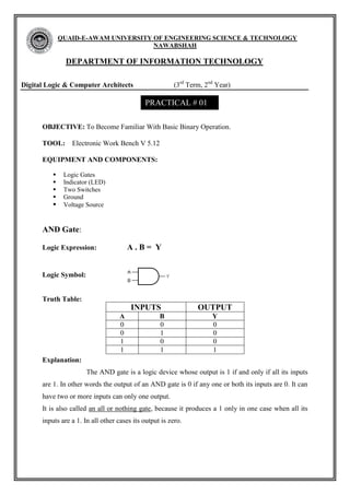
  • 1. QUAID-E-AWAM UNIVERSITY OF ENGINEERING SCIENCE & TECHNOLOGY NAWABSHAH DEPARTMENT OF INFORMATION TECHNOLOGY Digital Logic & Computer Architects (3rd Term, 2nd Year) PRACTICAL # 01 OBJECTIVE: To Become Familiar With Basic Binary Operation. TOOL: Electronic Work Bench V 5.12 EQUIPMENT AND COMPONENTS:  Logic Gates  Indicator (LED)  Two Switches  Ground  Voltage Source AND Gate: Logic Expression: A.B= Y Logic Symbol: Truth Table: INPUTS OUTPUT A B Y 0 0 0 0 1 0 1 0 0 1 1 1 Explanation: The AND gate is a logic device whose output is 1 if and only if all its inputs are 1. In other words the output of an AND gate is 0 if any one or both its inputs are 0. It can have two or more inputs can only one output. It is also called an all or nothing gate, because it produces a 1 only in one case when all its inputs are a 1. In all other cases its output is zero.
  • 2. QUAID-E-AWAM UNIVERSITY OF ENGINEERING SCIENCE & TECHNOLOGY NAWABSHAH DEPARTMENT OF INFORMATION TECHNOLOGY Digital Logic & Computer Architects (3rd Term, 2nd Year) PRACTICAL # 01 OR Gate: Logic Expression: A+B= Y Logic Symbol: Truth Table: INPUTS OUTPUT A B Y 0 0 0 0 1 1 1 0 1 1 1 1 Explanation: The OR gate is a logic device whose output is 1 if at least one if its input is 1. In other words the output of an OR gate is 0 if both its inputs are 0. It is also called any or all gate, because it produces a 1 even if one of its inputs is at 1. It produces a 0 only when all the inputs are 0.
  • 3. Viva Question: Q: 1 why we use logic Gates? Ans: Logic gates are used to make logic circuits. Q: 2 Advantages of logic gates? Ans: Logic gates are basic components of microprocessors. Without them, electronics systems couldn't run. Q: 3 what is also called NOT gate? Ans: The NOT gate also called INVERTER. Q: 4 Where output of AND Gate is high and low? Ans: If both inputs are high the output will be high/true/on else output of AND gate is low/false/off.
  • 4. QUAID-E-AWAM UNIVERSITY OF ENGINEERING SCIENCE & TECHNOLOGY NAWABSHAH DEPARTMENT OF INFORMATION TECHNOLOGY Digital Logic & Computer Architects (3rd Term, 2nd Year) PRACTICAL # 02 OBJECTIVE: To implement and verify the NOR gate, NAND gate operations. TOOL: Electronic Work Bench V 5.12 EQUIPMENT AND COMPONENTS:  Logic Gates  Indicator (LED)  Two Switches  Ground  Voltage Source NOR Gate: Logic Expression: ( A + B)¯ = Y Logic Symbol: Truth Table: INPUTS OUTPUT A B Y 0 0 1 0 1 0 1 0 0 1 1 0 Explanation: The NOR gate is a device whose out is 1 if and only if all inputs are at 0. In all other cases the output is 0. The name NOR is derived from NOT-OR, because the gate performs the same logic as OR gate followed by an inverter. It is a universal gate. It can also be used as an inverter.
  • 5. QUAID-E-AWAM UNIVERSITY OF ENGINEERING SCIENCE & TECHNOLOGY NAWABSHAH DEPARTMENT OF INFORMATION TECHNOLOGY Digital Logic & Computer Architects (3rd Term, 2nd Year) PRACTICAL # 02 NAND Gate: Logic Expression: ( A . B)¯ = Y Logic Symbol: Truth Table: INPUTS OUTPUT A B Y 0 0 1 0 1 1 1 0 1 1 1 0 Explanation: The NAND gate is a device whose output is 1 if at least one of its inputs is 0. Thus the output is 0 when all its inputs are 1. The name NAND is derived from NOT-AND because the gate performs the same logic as AND gate followed by an inverter. It is a universal gate as all basic gates can be derived from it. It can also be used as an inverter. VIVA QUESTIONS Q: 1 NOR gate is combination of? Ans: NOR gate is the combination of OR gate and NOT gate. Q: 2 NAND gate is combination of? sAns: NAND gate is combination of AND gate and NOT gate. Q: 3 Where output of NOR gate is high and low? Ans: If any one or both input is high the output will be low else output will high. Q: 4 where output of NAND gate is high and low? Ans: If both input high the output will be low else output will high.
  • 6. QUAID-E-AWAM UNIVERSITY OF ENGINEERING SCIENCE & TECHNOLOGY NAWABSHAH DEPARTMENT OF INFORMATION TECHNOLOGY Digital Logic & Computer Architects (3rd Term, 2nd Year) PRACTICAL # 03 OBJECTIVE: To understand the operation of EX-OR & EX-NOR gates. TOOL: Electronic Work Bench V 5.12 EQUIPMENT AND COMPONENTS:  Logic Gates  Indicator (LED)  Two Switches  Ground  Voltage Source EX-OR Gate: Logic Expression: F = x‟y + xy‟ Logic Symbol: Truth Table: INPUTS OUTPUT X Y F 0 0 0 0 1 1 1 0 1 1 1 0 Explanation: If inputs are similar output of X-OR gate will be “low” (0). If inputs are dissimilar or change than output of X-OR gate will be “High” (1).
  • 7. EX-NOR Gate: Logic Expression: F = x‟ y „ . x y Logic Symbol: Truth Table: INPUTS OUTPUT X Y F 0 0 1 0 1 0 1 0 0 1 1 1 Explanation: If inputs are similar output of X-NOR gate will be “High” (1). If inputs are dissimilar or change than output of X-OR gate will be “Low” (0). Viva Question: Q.01: What is operation of EX-OR gate? ANS: If inputs are similar output of EX-OR gate will be low. If inputs are dissimilar or change than output of EX-OR gate will be high. Q.02: What is operation of EX-NOR gate? ANS: If inputs are similar output of EX-NOR gate will be high. If inputs are dissimilar or change than output of EX-NOR gate will be low.
  • 8. QUAID-E-AWAM UNIVERSITY OF ENGINEERING SCIENCE & TECHNOLOGY NAWABSHAH DEPARTMENT OF INFORMATION TECHNOLOGY Digital Logic & Computer Architects (3rd Term, 2nd Year) PRACTICAL # 04 OBJECTIVE: To Design the circuit of the Boolean expression & verify the result through truth table. TOOL: Electronic Work Bench V 5.12 EQUIPMENT AND COMPONENTS:  Logic Gates  Indicator (LED)  Two Switches  Ground  Voltage Source 1. F= (a.b) (b`+c) Truth Table: S.No A B C F 0 0 0 0 0 1 0 0 1 0 2 0 1 0 0 3 0 1 1 0 4 1 0 0 0 5 1 0 1 0 6 1 1 0 0 7 1 1 1 1
  • 9. 2. F= (a`+b`) (c`+d) (d+c) Truth Table: S:NO A B C D F 0 0 0 0 0 0 1 0 0 0 1 1 2 0 0 1 0 0 3 0 0 1 1 1 4 0 1 0 0 0 5 0 1 0 1 1 6 0 1 1 0 0 7 0 1 1 1 1 8 1 0 0 0 0 9 1 0 0 1 1 10 1 0 1 0 0 11 1 0 1 1 1 12 1 1 0 0 0 13 1 1 0 1 0 14 1 1 1 0 0 15 1 1 1 1 0
  • 10. 3. F= {(x`+y) `+(x+y) `+(y+z`)} Truth Table: S:NO X Y Z F 0 0 0 0 1 1 0 0 1 1 2 0 1 0 0 3 0 1 1 1 4 1 0 0 0 5 1 0 1 0 6 1 1 0 1 7 1 1 1 1
  • 11. 4. F= [(a+b+c) `] [(d`e)] Truth Table: S:NO A B C D E F 0 0 0 0 0 0 0 1 0 0 0 0 1 0 2 0 0 0 1 0 0 3 0 0 0 1 1 0 4 0 0 1 0 0 0 5 0 0 1 0 1 1 6 0 0 1 1 0 0 7 0 0 1 1 1 0 8 0 1 0 0 0 0 9 0 1 0 0 1 1 10 0 1 0 1 0 0 11 0 1 0 1 1 0 12 0 1 1 0 0 0 13 0 1 1 0 1 1 14 0 1 1 1 0 0 15 0 1 1 1 1 0
  • 12. QUAID-E-AWAM UNIVERSITY OF ENGINEERING SCIENCE & TECHNOLOGY NAWABSHAH DEPARTMENT OF INFORMATION TECHNOLOGY Digital Logic & Computer Architects (3rd Term, 2nd Year) PRACTICAL # 05 OBJECTIVE: To observe the operation of logic converter. TOOL: Electronic Work Bench V 5.12 EQUIPMENT AND COMPONENTS:  Logic Gates  Indicator (LED)  Two Switches  Ground  Voltage Source THEORY: The logic converter is able to perform several transformations of a circuit representation. It has no real-world counterpart. It can be attached to a circuit to derive the truth table or Boolean expression the circuit embodies, or used to produce a circuit from a truth table or Boolean expression. PROCEDURE: 1. First we open the electronic workbench. 2. Get an OR gate. 3. Two NOT gates and tow AND gates from logic gates and one converter. 4. Connect inputs to left side of converter and output to the right side of the converter.
  • 13. TO CONSTRUCT A TRUTH TABLE: 1. Click the number of input channels you want, from a to H, across the top of the logic converter. The display area below the terminals fills up with the necessary combinations of ones and zeros to fulfill the input conditions. The values in the output column on the right are initially set to 0. 2. Edit the output column to specify the desired output for each input condition. To change an output value, select it and type a new value: 1, 0 or x. (An x indicates that either 1 or 0 is acceptable.) To convert a truth table to a Boolean expression, click the Truth Table to Boolean Expression button. The Boolean expression will be displayed at the bottom of the logic converter. To convert a truth table to a simplified Boolean expression, or to simplify an existing Boolean expression, click the Simplify button which is shown in the figure. RESULT:  The result is observed by the logic converters.
  • 14. QUAID-E-AWAM UNIVERSITY OF ENGINEERING SCIENCE & TECHNOLOGY NAWABSHAH DEPARTMENT OF INFORMATION TECHNOLOGY Digital Logic & Computer Architects (3rd Term, 2nd Year) PRACTICAL # 06 OBJECTIVE: Task 1: Design full adder circuit. Task 2: Design a BCD to Excess-3 code converter. TOOL: Electronic Work Bench V 5.12 EQUIPMENT AND COMPONENTS:  Logic Gates  Indicator (LED)  Two Switches  Ground  Voltage Source THEORY: FULL ADDER: A full adder is a combinational circuit that performs an arithmetic sum of three input bits and produces two outputs.
  • 15. BCD TO EX-3: The BCD to Ex-3 code uses four bit to represent a decimal digits there must be four input Variable.
  • 16. QUAID-E-AWAM UNIVERSITY OF ENGINEERING SCIENCE & TECHNOLOGY NAWABSHAH DEPARTMENT OF INFORMATION TECHNOLOGY Digital Logic & Computer Architects (3rd Term, 2nd Year) PRACTICAL # 07 OBJECTIVE: Design a combinational circuit the multiply two numbers of two bit each TOOL: Electronic Work Bench V 5.12 EQUIPMENT AND COMPONENTS:  Logic Gates  Indicator (LED)  Two Switches  Ground  Voltage Source
  • 17. TRUTH TABLE: a1 a0 b1 b0 w x y z 0 0 0 0 0 0 0 0 0 0 0 1 0 0 0 0 0 0 1 0 0 0 0 0 0 0 1 1 0 0 0 0 0 1 0 0 0 0 0 0 0 1 0 1 0 0 0 1 0 1 1 0 0 0 1 0 0 1 1 1 0 0 1 1 1 0 0 0 0 0 0 0 1 0 0 1 0 0 1 0 1 0 1 0 0 1 0 0 1 0 1 1 0 1 1 0 1 1 0 0 0 0 0 0 1 1 0 1 0 0 1 1 1 1 1 0 0 1 1 0 1 1 1 1 1 0 0 1