EXPERIMENT 1 : introduction to electric and electronic devices
•Descargar como DOCX, PDF•
1 recomendación•1,374 vistas


Recomendados
Más contenido relacionado
La actualidad más candente
La actualidad más candente (20)
Destacado
Similar a EXPERIMENT 1 : introduction to electric and electronic devices
Similar a EXPERIMENT 1 : introduction to electric and electronic devices (20)
Último
Último (20)
EXPERIMENT 1 : introduction to electric and electronic devices
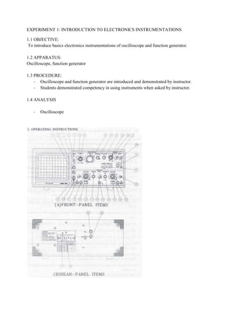
- 1. EXPERIMENT 1: INTRODUCTION TO ELECTRONICS INSTRUMENTATIONS 1.1 OBJECTIVE: To introduce basics electronics instrumentations of oscilloscope and function generator. 1.2 APPARATUS: Oscilloscope, function generator 1.3 PROCEDURE: - Oscilloscope and function generator are introduced and demonstrated by instructor. - Students demonstrated competency in using instruments when asked by instructor. 1.4 ANALYSIS - Oscilloscope
- 2. ITEM FUNCTION 1 Power switch Push in to turn instrument power on and off 2 Power lamp Lights when power is on. 3 Inten control Adjust the brightness of the CRT display, increase brightness . 4 Focus control To obtain maximum trace sharp. 5 Rotation control Allow screwdriver adjustment of trace alignment with regard to the horizontal line of graticule CRT. 6 Illum control To adjust graticul illumination for photographing CRT display. 7 Voltage selector Permits changing the operating voltage range. 8 Power connector Permits removal or replacement of AC power record. 9 CH1 or X IN connector For applying an input signal to vertical-amplifier channel 1, or to x-axis (horizontal) amplifier during X-Y operation 10 CH2 or Y IN connector For applying an input signal to vertical amplifier channel 2, or to Y-axis (vertical) amplifier during X-Y operation. 11 CH1 AC/ GND /DC To select the method of coupling the input signal to the switch CH1 vertical amplifier. AC position inserts a capacitor between the input connector and amplifier to block any DC component in the input signal. GND position connects the amplifier to ground. Instead of the input connector, so a ground reference can be established. DC position connects the amplifier directly to its input connector, thus passing all signal components on the amplifier. 12 CH2 AC / GND / DC To select the method of coupling the input signal to the switch CH2 vertical amplifier. 13 CH1 volts/div switch To select the calibrated deflection factor of the input signal fed to the CH1 vertical amplifier. 14 CH2 volts/div switch To select the calibrated deflection factor of the input signal fed to the CH2 vertical amplifier 15 Variable control (on Provide continuously variable adjustment of deflection variable) factor between steps of the volts /div switches. Volts/div calibrations are accurately only when the variable controls are click stopped in their fully clockwise position. 16 Variable control (on (same as 15) variable) 17 CH1 position control For vertically positioning the CH1 trace on the CRT screen, Clockwise rotation moves the trace up, counterclockwise rotation moves the trace down. 18 CH2 position For vertically positioning the CH2 trace on the CRT screen. Clockwise rotation moves the trace up, counterclockwise rotation moves the trace downward. 18 Pull CH2 inv switch (on When pulled, the polarity of the CH2 signal is inverted CH2 position control) 19 V mode switch When pulled, the polarity of the CH2 signal is inverted.To select the vertical-amplifier display
- 3. mode.CH1 position displays only the channel 1 Input signal on the CRT screen.CH2 position displays only the channel 2. Input signal on the CRT screen dual. 20 21 Horiz display switches To select the sweep mode.A pushbutton sweeps the CRT at the main (A).Timebase rate when pressed. A INT pushbutton sweeps the CRT at the main (A) timebase rate when pressed, and the B timebase intensifies a section of the trace(s) The location of the intensified section is determined by the delay time pos control. B pushbutton sweeps the CRT at the rate selected. By the B time/div switch, after a delay determined by the A time/div switch and the delay time pos control. X-Y push button provides X-Y operation. B TRIG’D pushbutton sweeps the CRT at the rate selected by the B time dib switch when triggered by the first trigger pulse occurring after the delay time determined by the A time/div switch and the delay time pos control. 22 A time/div switch To select either the calibrated sweep rate of the main (A) timebase, the delay-time range for delayed-sweep operation. 23 B time/div switch To select the calibrated sweep rate of the delayed (B) timebase. 24 Delay time pos control To determine the exact starting point within the A timebase delay range at which the B timebase will begin sweepin 25 A variable control Provides continuously variable adjustment of sweep rate between steps of the A time/div switch. Time/div calibrations are accurate only when the A variable control is click-stopped fully clockwise. 26 Horizontal position control To adjust the horizontal position of the traces control displayed on the CRT. Clockwise rotation moves the traces to the right, counterclockwise rotation moves the traces to the left. 27 Trigger mode switch To select the sweep triggering mode. Auto position selects free-running sweep where a baseline is displayed in the absense of a signal. This condition automatically reverts to triggered sweep when a trigger signal of 25 Hz or higher is received and other trigger controls and properly set. NORM position produces sweep only when a trigger signal is received and other controls are properly set.No trace is visible if any trigger requirement is missing. This mode must be used when the signal frequency is 25 Hz or lower. TV-V position is used for observing a composite video signal at the frame rate. TV- H position is used for observing a compositevideo signal at the frame rate. 28 Trigger source switch To conveniently select the trigger source. CH1 position selects the channel 1 signal as the trigger source. CH2
- 4. position selects the channel 2 signal as the trigger source. Line position selects a trigger derived from the AC power line. This permits the scope to sta-bilize display line- related components of a signal even if they are very small compared to other components of the signal. Ext position selects the signal applied to the ext trig in connector. 29 Hold off control Allows triggering on certain complex signals by changing the holdoff (dead) time of the main (A) sweep.This avoids triggering on intermediate trigger points within the repetition cycle of the desired display. The holdoff time increases with clockwise rotation. NORM is a position at full counterclockwise rotation that is used for ordinary signals. 30 Trigger level control To select the trigger-signal amplitude at which triggering occurs. When rotated clockwise, the trigger point moves toward the positive peak of the trigger signal. When this control is rotated counterclockwise, the trigger point moves toward the negative peak of the trigger signal. 30 Trigger slope switch To select the positive or negative slope of the trigger (on level control) signal for initiating sweep. Pushed in, the switch selects the positive (+) slope. When pulled, this switch selects the negative (-) slope. 31 Ext trig in connector For applying external trigger signal to the trigger circuits. 32 Ext blanking input For applying signal to intensity modulate the CRT. Trace connector brightness is reduced with a positive signal, and increased with a negative signal. 33 Cal connector Provides a fast-rise square wave of precise amplitude for probe adjustment and vertical amplifier calibration. 34 Ground connector Provides an attachment point for a separate ground lead. - Function generator ITEM FUNCTION 1 Power ON When lighted, indicates a power on condition. light 2 Amplitude This variable control, depending on the position of the volts out button, Control determines the level of the signal at the main output connector. 3 DC offset Pull out this control to activate. The DC offset control sets the DC level
- 5. and polarity of the signal at the main output. When the control is pressed in, the signal is centered at zero VDC. 4 Symmetry This knob changes the duty cycle of a square wave signal or the rise and Knob fall times of sawtooth and sine wave signals. This feature is called symmetry because it affects the visual symmetry of the wave form along its longitudinal axis. The knob has no effect unless the symmetry button (see item 11) is pushed in. When the symmetry knob is at the center position, the symmetry of the waveform is unaffected. Rotating the knob clockwise has an increasing effect on the waveform; rotating the knob counterclockwise has the opposite effect. (table 1 ) 5 Range (Hz) These buttons determine the frequency range of the signal at the main Buttons output connector. 6 Function The sine, square or sawtooth buttons select the type of signal provided at Buttons the main output connector 7 Frequency This variable control determines the frequency of the signal at the main Control output connector within the range set by the range buttons. 8 Sweep This control adjusts the sweep amplitude . This control adjusts the sweep Width amplitude. 9 Sweep Rate This control adjusts the rate of the internal sweep generator and the repetition rate of the burst gate. 10 Sweep Push in for internal sweep. This button activates the sweep rate and Button sweep width controls. When the button is set out, the function generator accepts signals from its external sweep input connector on the rear panel. 11 Symmetry Pushing this button in divides the frequency of the output signal by ten Button and allows the symmetry of the signal to be varied using the symmetry knob (see item 4). Table 1 shows effects of adjusting the symmetry on waveforms. 12 Volts Out Push in for amplitude control range of 0 to 2 Vp-p, open circuit, or 0 to 1 Button Vp-p into a 50 Ω load. Set to the out position for an amplitude control range of 0 to 20 Vp-p, in an open circuit, or 0 to 10 Vp-p to a 50 Ω load 13 Sync (Ttl) BNC output connector for TTL signals. Output 14 Main BNC output connector for sine wave, square wave and sawtooth wave Output signals. 15 Power Push in to turn function generator on. A secondpush turns the function Button generator off.