SlideShare una empresa de Scribd logo
1 de 42
Descargar para leer sin conexión
11/5/2019 Unit II Coupling 1
COUPLING
2
Coupling
• Shafts are usually available up to 7 m length due to
inconvenience in transport. In order to have a greater length,
it becomes necessary to join two or more pieces of the shaft
by means of a coupling.
• A Coupling can be defined as a mechanical device that
rigidly joins two rotating shafts to each other.
• Uses:-
 To Provide connections of shafts
 To provide mechanical flexibility for misalignment of
shaft
 To reduce transmission of shock loads from one shaft to
another shaft.
 To introduce protection against overloads.
11/5/2019 Unit II Coupling
Unit II Coupling 3
Types of coupling
1. Rigid coupling- to connect two shafts which are
perfectly aligned.
(a) Sleeve or muff coupling
(b) Clamp or compressive coupling
(c) Flange coupling
2. Flexible coupling- to connect two shafts having both
lateral and angular misalignment.
(a) Bushed pin coupling
(b) Universal coupling
(c) Oldham coupling
11/5/2019
11/5/2019 Unit II Coupling 4
Unit II Coupling 5
1. Sleeve or Muff coupling
11/5/2019
Problem 1. Design a muff
coupling which is used to
connect two steel shafts
transmitting 25 kW power
at 360 rpm. The shafts and
key are made of plain
carbon steel 30C8
(Syt=Syc= 400N/mm2). The
sleeve is made of grey
cast iron FG 200 (Sut= 200
N/mm2). The factor of
safety for the shafts and
key is 4. For sleeve the
factor of safety is 6 based
on ultimate strength.
Nov-Dec 2016, April May- 2013
Unit II Coupling 6
Design of sleeve or muff coupling
1. Design for shaft:
find diameter of the shaft using equation
2. Design for sleeve:
• Find outer dia. of sleeve using relation
D = 2d +13 mm & L= 3.5 d
• Check induced shear stress in the sleeve using equation
Where Mt = Torque to be transmitted by the coupling
τ = Permissible shear stress for the material of the sleeve
which is cast iron
3
1660
2
t
t
MP
M and
n d

 

 
 44
16
dD
DMt




11/5/2019
Unit II Coupling 7
Cont…
3. Design for key:
 For Parallel (rectangular and square sunk) keys
• Refer Data book page no. 5.16 and select width(b) and height (h)
of the key for given shaft diameter (d).
• Length of the coupling key = 3.5 d
length of the key in each shaft l = L/2 = 3.5d/2
 Check for shearing and crushing stress
(considering shear of key)
(considering crushing of key)
2 tM
dbl
 
4 t
c
M
dhl
 
11/5/2019
11/5/2019 Unit II Coupling 8
Data Book page No. 5.16
DIMENSIONS OF PARALLEL KEYS AND KEYWAYS
Unit II Coupling 9
Problem 1. Design a muff coupling which is used to
connect two steel shafts transmitting 25 kW power at
360 rpm. The shafts and key are made of plain carbon
steel 30C8 (Syt=Syc= 400N/mm2). The sleeve is made of
grey cast iron FG 200 (Sut= 200 N/mm2). The factor of
safety for the shafts and key is 4. For sleeve the factor of
safety is 6 based on ultimate strength.
Nov-Dec 2016, April May- 2013
11/5/2019
Unit II Coupling 10
Problem 2. Design a rigid muff coupling. Use CI for
the muff. The power transmitted is 25 kW at 300
rpm. Ultimate tensile strength =200 MPa and
factor of safety =6. Use 30C8 for the shaft
considered. Yield Point stress = 330 Mpa and
factor of safety =4.
(April-May 2012, Nov- Dec 2013)
11/5/2019
Unit II Coupling 11
Problem 3. Design and make a neat dimensioned
sketch of a muff coupling, which is used to
connect two steel shafts transmitting 40 kW at
350 rpm. The material for the shaft and key is
plain carbon steel for which allowable shear and
crushing stresses may be taken as 40 MPa and
80 MPa respectively. The material for the muff is
cast iron for which the allowable shear stress
may be assumed 15 MPa.
(Nov-Dec 2012)
11/5/2019
Unit II Coupling 12
2. Clamp or compression coupling (split muff coupling)
11/5/2019
Unit II Coupling 13
Dimensions for clamp coupling
 For sleeve halves,
Outer diameter of the sleeve D= 2.5 d,
Length of the sleeve L= 3.5 d
 For clamping bolts,
Diameter of the claming bolt may be find out either
1. By using empirical equations:
d1= 0.2 d + 10 mm (when d< 55 mm)
And d1= 0.15 d + 15 mm (when d> 55 mm)
or
2. By using following equations: (assuming that power is transmitted
by friction)
Where P1 = Tensile force on each bolt
d1 = core diameter of clamping bolt
n = total no. of bolts & f= coefficient of friction
2
1 1 1
2
4
t
t
M
P and P d
fdn

 
11/5/2019
Unit II Coupling 14
Design Procedure
Step 1. Calculate the diameter of each shaft.
Step 2. Calculate the main dimensions of the sleeve halves.
Step 3. Determine the standard cross-section of flat key from data book
page no. 5.16.
Length of the key in each shaft l = L / 2 = 3.5 d / 2
check the shear stress and compressive stress by using,
and
Step 4. calculate the diameter of clamping bolts by using
2 tM
dbl
 
4 t
c
M
dhl
 
2
1 1 1
2
4
t
t
M
P and P d
fdn

 
11/5/2019
Unit II Coupling 15
Problem 1. It is required to design a split muff coupling to
transmit 50 kW power at 120 rpm. The shafts, key and
coupling bolts are made of plain carbon steel 30C8 (Syt= 400
N/mm2). The yield strength in compression is 150% of tensile
yield strength. The factor of safety for shafts key and bolts is
5. The number of clamping bolts is 8. The coefficient of friction
between sleeve halves and the shaft is 0.3.
(i) Calculate the diameter of input and output shaft.
(ii) Specify length and outer diameter of sleeve halves.
(iii) Find out the diameter of clamping bolts assuming that the
power is transmitted by friction.
(iv) Specify bolt diameter using standard empirical relations.
(v) Specify the size of key and check the dimensions for shear
and compression criteria.
11/5/2019
April-May 2017
Unit II Coupling 16
Problem 2. design a clamp coupling to transmit 30
kW at 100 rpm. The allowable shear stress for
the shaft and key is 40 MPa and the number of
bolts connecting the two halves are six. The
permissible tensile stress for the bolts is 70
MPa. The coefficient of friction between the muff
and the shaft surface may be taken as 0.3.
11/5/2019
Unit II Coupling 17
3. Rigid flange coupling
(A) Unprotected type flange coupling (B) Protected type flange coupling
11/5/2019
Advantages:-
1.High torque
transmitting capacity
2.Easy to assemble and
dismantle.
3.Simple construction,
easy to design and
manufacture.
Disadvantages:-
1.Does not tolerate
misalignment.
2.Unsuitable for shock
and vibration.
3.Requires more radial
spaces.
Unit II Coupling 1811/5/2019
Unit II Coupling 19
Protected type flange coupling
11/5/2019
Unit II Coupling 20
Dimensions for protected type flange coupling
• Outside diameter of hub dh= 2d
• Length of hub or effective length of key lh = 1.5 d
• Pitch circle diameter of bolts D= 3d
• Thickness of flanges t = 0.5 d
• Thickness of protective rim t1 = 0.25 d
• Diameter of spigot and recess dr = 1.5 d
• Outside diameter of flange Do= 4d+2t1
• Number of bolts = 3, for d < 40 mm
= 4, for 40 ≤ d <100 mm
= 6, for 100 ≤ d < 180 mm
11/5/2019
Design of flange coupling
Unit II Coupling 21
1. Shaft diameter
find diameter of the shaft using equations
3
1660
2
t
t
MP
M and
n d

 

 
11/5/2019
Unit II Coupling 22
2. Dimensions of flange:
dh= 2d
lh = 1.5 d
D= 3d
t = 0.5 d
 Check for torsional shear stress in the hub:-
 Check for shear stress in the flange at the junction with
the hub:-
t1 = 0.25 d
dr = 1.5 d
Do= 4d+2t1
td
M
h
t
2
2

 
 4 4
32 2
ht h
d dM r d
where J and r
J



  
11/5/2019
3. Diameter of bolts:
Number of bolts N= 3, for d < 40 mm
N= 4, for 40 ≤ d <100 mm
N= 6, for 100 ≤ d < 180 mm
diameter of bolt is determined by using equation:-
Check compressive stress in bolt:-
Unit II Coupling
23
DN
M
d t82
1 
tDNd
Mt
c
1
2

11/5/2019
11/5/2019 Unit II Coupling 24
THREADS FOR BOLTS AND NUTS
COARSE AND FINE SERIES
Unit II Coupling 25
4. Design for key:
 For Parallel (rectangular and square sunk) keys
• Width X height (b x h) of the key:-
Refer PSG Data book page no. 5.16
• length of the key in each shaft l = lh = 1.5 d
 Check shearing and crushing stress
2 tM
dbl
 
4 t
c
M
dhl
 
11/5/2019
Unit II Coupling 26
Problem 1. Design a cast iron protective type flange
coupling to transmit 15 kW at 900 rpm from an electric
motor to a compressor. The service factor may be
assumed as 1.35. The following permissible stresses
may be used:
Shear stress for shaft, bolt and key material = 40 MPa
Crushing stress for bolt and key = 80 MPa
Shear stress for cast iron = 8 MPa
Draw also a neat sketch of the coupling.
(April May 2015, Nov-Dec 2013)
11/5/2019
Unit II Coupling 27
Problem 2. Design and draw a protective type of
cast iron flange coupling for a steel shaft
transmitting 15 kW at 200 rpm and having an
allowable shear stress of 40 MPa. The working
stress in the bolts should not exceed 30 MPa.
Assume that the same material is used for shaft
and key and that the crushing stress is twice the
value of its shear stress. The maximum torque is
25% greater than the full load torque. The shear
stress for cast iron is 14 MPa. (2008 Supp.)
11/5/2019
Unit II Coupling 28
Problem 3. Two 35 mm shafts are connected by a flanged
coupling. The flanges are fitted with 6 bolts on 125 mm
pitch circle diameter of bolts. The shaft transmit a torque
of 800 N-m at 300 rpm. For the safe stresss mentioned
below calculate: (i) diameter of bolts (ii) thickness of
flanges (iii) Key dimensions (iv) hub length and (v) Power
transmitted
Safe shear stresses for shaft material = 63 MPa, Safe
shear stress for bolt material = 56 MPa, safe shear stress
for cast iron coupling = 10 MPa, Safe shear stress for key
material = 46 MPa
Also draw the line sketch of flange coupling.
(Nov-Dec 2011)
11/5/2019
Unit II Coupling 29
Problem 4. A rigid flange coupling is used to transmit 15
kW power at 720 rpm between two steel shaft. The shaft
key and bolt are made of plain carbon steel 30C8 (Syt=
400 N/mm2), FOS= 3. The yield strength in compression
may be taken as 150 % of tensile yield strength. The
flanges are made of grey cast iron of grade FG200 (Sut=
200 N/mm2), FOS= 6. The keys have square cross
section. Design a coupling and specify the dimensions of
its part.
11/5/2019
Unit II Coupling 30
Problem 5. A rigid flange coupling is required to transmit 50
kW at 300 rpm. There are six bolts. The outer diameter is of
flange is 200 mm and diameter of recess is 150 mm. The
coefficient of friction between the flanges is 0.15. The shaft
and bolt are made of plain carbon steel 45C8 (Syt= 380
N/mm2), fos= 3. Determine the diameter of the bolts.
Assume that the bolts are set in large clearance holes.
11/5/2019
11/5/2019 Unit II Coupling 31
(April-May 2016)
11/5/2019 Unit II Coupling 32
(April-May 2015)
11/5/2019 Unit II Coupling 33
(Nov-Dec 2015)
11/5/2019 Unit II Coupling 34
(Nov-Dec 2014)
Unit II Coupling 35
4. Bushed-pin flexible coupling
11/5/2019
36
Step 1. Shaft diameter:-
Step 2 . Dimension of flange:-
• dh= outside diameter of hub= 2d
• lh= length of hub or effective length of key = 1.5d
• D= pitch circle diameter of pins= 3d to 4d
• t= thickness of output flanges = 0.5d
• t1= thickness of protective rim= 0.25d
• The torsional shear stress in the hub is given by-
Design procedure for flexible coupling
 4 4
32 2
ht h
d dM r d
where J and r
J



  
11/5/2019 Unit II Coupling
Unit II Coupling 37
• The shear stress in the flange at the junction with the hub is given by:-
Step 3. Dimensions of bushes:-
• Outer diameter of rubber bush (Db) is determined from the equation.
• Where pm is pressure between bush and C.I. flange (usually 1N/mm2 )
• Effective length of the rubber bush lb= Db
Step 4. Diameter of Pins:-
• Diameter of pins , Number of pins (n) is usually 4 or 6.
• Determine the shear stress in the pins by,
11/5/2019
td
M
h
t
2
2

 
Unit II Coupling 38
Step 5. Check for bending stress in pins:
 Torque transmitted by the coupling:
From above equation force P on each rubber bush or pin is determined.
 Bending moment on the pin is given by:
 Bending stress is checked by equation:
11/5/2019
Unit II Coupling 39
Step 6. Dimensions of keys:
 Determine the standard cross-section of flat key from
data book page no. 5.16.
 Length of the key l = length of hub = lh =1.5d
 check the shear stress and compressive stress by using,
2 tM
dbl
 
4 t
c
M
dhl
 
11/5/2019
Unit II Coupling 40
Problem 1. A bushed pin type flexible coupling is used to
connect two shafts and transmit 5 kW power at 720 rpm.
Shafts, keys and pins are made of commercial steel
(Syt=Syc=240 N/mm2) and the factor of safety is 3. The flanges
are made of grey cast iron FG200 (Sut= 200 N/mm2) and the
factor of safety is 6. Assume
Ssy=0.5 Syt and Ssu= 0.5 Sut
There are 4 pins. The pitch circle diameter of the pins is four
times of shaft diameter. The permissible shear stress for pins
is 35 N/mm2. The bearing pressure for rubber bushing is 1
N/mm2. The keys have square cross section. Calculate:
(i) diameter of the shafts
(ii) dimensions of flange and hub
(iii) dimensions of the key
(iv) diameter of the pins
(v) outer diameter and effective length of the bushes.
11/5/2019
Unit II Basic Elements Design 41
Assignment-2
Que.1 Design a Knuckle joint (with fork and eye) to with stand a load of
10,000 N. The materials used for all components have the following
properties ultimate tensile strength = ultimate compressive strength
= 480 N/mm2. Shear strength = 360 N/mm2. Factor of safety =6.
After design, draw a neat proportioned sketch of joint giving all
dimensions.
Que.2 Design a cotter joint to carry a maximum load of 50,000 N. All
components are made of the same material having the following
allowable stresses. (Sleeve and cotter joint)
Tensile stress = 20 MN/m2
Compressive stress = 50 MN/m2
Shear stress = 15 MN/m2
Draw a proportioned neat sketch of the joint you have designed.
Que.3 It is required to design a square key for fixing a pulley on the
shaft which is 50 mm in diameter. A 10 kW power at 200 r.p.m. is
transmitted by the pulley to the shaft. The key is made of steel 45C8
(Syt= Syc= 380 N/mm2) and the factor of safety is 3. Determine the
dimensions of the key.
11/5/2019
42
Que. 4 Design a C.I. flange coupling to transmit 150 H.P. at 250 rpm.
The following permissible stresses may be used:
Permissible shear stress for shaft, bolt and key material = 50 N/mm2
Permissible crushing stress for bolt and key material = 150 N/mm2
Permissible shear stress for Cast iron = 8 N/mm2
(Nov-Dec 2010)
Que.5 It is required to design a bushed pin type of flexible coupling for connecting
the motor to a centrifugal pump shafts. The details of the duty required from
the pump are:
Power to be transmitted = 18.5 kW
Speed in rpm = 1000
The diameters of the motor and pump shafts are 50 mm and 45 mm
respectively. Take the bearing pressure on the rubber bush as 0.35 N/mm2
and the working shear stress in the material of the pins as 20 N/mm2.
(2009)
11/5/2019 Unit II Coupling

Más contenido relacionado

La actualidad más candente

Introduction & Design of Bevel Gears
Introduction & Design of Bevel GearsIntroduction & Design of Bevel Gears
Introduction & Design of Bevel GearsDhrumit Patel
 
Design against fluctuating load
Design against fluctuating loadDesign against fluctuating load
Design against fluctuating loadSurajKumarChand1
 
DESIGN OF SOLID TRANSMISSION SHAFT
DESIGN OF SOLID TRANSMISSION SHAFTDESIGN OF SOLID TRANSMISSION SHAFT
DESIGN OF SOLID TRANSMISSION SHAFTAnimesh Bhattacharya
 
Unit 4 Design of Power Screw and Screw Jack
Unit 4 Design of Power Screw and Screw JackUnit 4 Design of Power Screw and Screw Jack
Unit 4 Design of Power Screw and Screw JackMahesh Shinde
 
Kinematic Synthesis
Kinematic SynthesisKinematic Synthesis
Kinematic SynthesisYatin Singh
 
Spur gear problem and solution
Spur gear   problem and solutionSpur gear   problem and solution
Spur gear problem and solutiondodi mulya
 
Balancing, Theory of Machine PPT
Balancing, Theory of Machine PPTBalancing, Theory of Machine PPT
Balancing, Theory of Machine PPTKjbhingare
 
Design of transmission elements
Design of transmission elementsDesign of transmission elements
Design of transmission elementsshone john
 
DESIGN AGAINST FLUCTUATING LOAD
DESIGN AGAINST FLUCTUATING LOADDESIGN AGAINST FLUCTUATING LOAD
DESIGN AGAINST FLUCTUATING LOADPriyank Gandhi
 
Design procedure for Cast iron pulley, Flat belt drive, V belt drive, Chain d...
Design procedure for Cast iron pulley, Flat belt drive, V belt drive, Chain d...Design procedure for Cast iron pulley, Flat belt drive, V belt drive, Chain d...
Design procedure for Cast iron pulley, Flat belt drive, V belt drive, Chain d...Dr.S.Thirumalvalavan
 
Numerical problems on spur gear (type i)
Numerical problems on spur gear (type i)Numerical problems on spur gear (type i)
Numerical problems on spur gear (type i)taruian
 

La actualidad más candente (20)

Introduction & Design of Bevel Gears
Introduction & Design of Bevel GearsIntroduction & Design of Bevel Gears
Introduction & Design of Bevel Gears
 
Design against fluctuating load
Design against fluctuating loadDesign against fluctuating load
Design against fluctuating load
 
DESIGN OF SOLID TRANSMISSION SHAFT
DESIGN OF SOLID TRANSMISSION SHAFTDESIGN OF SOLID TRANSMISSION SHAFT
DESIGN OF SOLID TRANSMISSION SHAFT
 
Unit 4 Design of Power Screw and Screw Jack
Unit 4 Design of Power Screw and Screw JackUnit 4 Design of Power Screw and Screw Jack
Unit 4 Design of Power Screw and Screw Jack
 
Kinematic Synthesis
Kinematic SynthesisKinematic Synthesis
Kinematic Synthesis
 
Spur gear problem and solution
Spur gear   problem and solutionSpur gear   problem and solution
Spur gear problem and solution
 
Balancing, Theory of Machine PPT
Balancing, Theory of Machine PPTBalancing, Theory of Machine PPT
Balancing, Theory of Machine PPT
 
Knuckle joint silde
Knuckle joint sildeKnuckle joint silde
Knuckle joint silde
 
Design of transmission elements
Design of transmission elementsDesign of transmission elements
Design of transmission elements
 
Unit 2 design of shaft
Unit 2 design of shaftUnit 2 design of shaft
Unit 2 design of shaft
 
Unit1 designof levers
Unit1 designof leversUnit1 designof levers
Unit1 designof levers
 
DESIGN AGAINST FLUCTUATING LOAD
DESIGN AGAINST FLUCTUATING LOADDESIGN AGAINST FLUCTUATING LOAD
DESIGN AGAINST FLUCTUATING LOAD
 
Design procedure for Cast iron pulley, Flat belt drive, V belt drive, Chain d...
Design procedure for Cast iron pulley, Flat belt drive, V belt drive, Chain d...Design procedure for Cast iron pulley, Flat belt drive, V belt drive, Chain d...
Design procedure for Cast iron pulley, Flat belt drive, V belt drive, Chain d...
 
Capston and turrent lathe
Capston and turrent latheCapston and turrent lathe
Capston and turrent lathe
 
Limits,fits and tolerances
Limits,fits and tolerancesLimits,fits and tolerances
Limits,fits and tolerances
 
Design of Helical Spring
Design of Helical SpringDesign of Helical Spring
Design of Helical Spring
 
Unit 2b Power Transmission by Belts
Unit 2b Power Transmission by BeltsUnit 2b Power Transmission by Belts
Unit 2b Power Transmission by Belts
 
Numerical problems on spur gear (type i)
Numerical problems on spur gear (type i)Numerical problems on spur gear (type i)
Numerical problems on spur gear (type i)
 
V belt drives
V belt drivesV belt drives
V belt drives
 
Merchant's circle
Merchant's circleMerchant's circle
Merchant's circle
 

Similar a Unit 2.3 Design of Coupling

Unit 2.1 basic elements design
Unit 2.1 basic elements designUnit 2.1 basic elements design
Unit 2.1 basic elements designYugal Kishor Sahu
 
Couplings by wishall
Couplings by wishallCouplings by wishall
Couplings by wishallvishal patil
 
Couplings by wishall patil
Couplings by wishall patilCouplings by wishall patil
Couplings by wishall patilvishal patil
 
Shaft. keys and cuopling
Shaft. keys and cuoplingShaft. keys and cuopling
Shaft. keys and cuoplingSvabhiman Singh
 
ch-02_cotter-joint-knuckle-joint-design.pdf
ch-02_cotter-joint-knuckle-joint-design.pdfch-02_cotter-joint-knuckle-joint-design.pdf
ch-02_cotter-joint-knuckle-joint-design.pdfPraveen Kumar
 
Design and Construction of a Connecting rod
Design and Construction of a Connecting rodDesign and Construction of a Connecting rod
Design and Construction of a Connecting rodFaisal Niloy
 
Design & Construction of a Connecting rod
Design & Construction of a Connecting rodDesign & Construction of a Connecting rod
Design & Construction of a Connecting rodFaisal Niloy
 
A COMPARATIVE STUDY ON RIGID CONNECTION DESIGN OF FRAMED MULTI STOREYED STEEL...
A COMPARATIVE STUDY ON RIGID CONNECTION DESIGN OF FRAMED MULTI STOREYED STEEL...A COMPARATIVE STUDY ON RIGID CONNECTION DESIGN OF FRAMED MULTI STOREYED STEEL...
A COMPARATIVE STUDY ON RIGID CONNECTION DESIGN OF FRAMED MULTI STOREYED STEEL...IRJET Journal
 
Me ies-2014-conventional-ii
Me ies-2014-conventional-iiMe ies-2014-conventional-ii
Me ies-2014-conventional-iikrutti
 
Coupling and flange coupling and its design
Coupling and flange coupling and its designCoupling and flange coupling and its design
Coupling and flange coupling and its designRupesh Kumar
 
ANALYSIS OF KNUCKLE JOINT
ANALYSIS OF KNUCKLE JOINTANALYSIS OF KNUCKLE JOINT
ANALYSIS OF KNUCKLE JOINTOmkar Kamodkar
 
Engineering plant facilities 15 mechanics welding
Engineering plant facilities 15 mechanics weldingEngineering plant facilities 15 mechanics welding
Engineering plant facilities 15 mechanics weldingLuis Cabrera
 
Ce6603 design of steel structures qb
Ce6603 design of steel structures qbCe6603 design of steel structures qb
Ce6603 design of steel structures qbsaibabu48
 
Bushed pin type flexible coupling
Bushed pin type flexible couplingBushed pin type flexible coupling
Bushed pin type flexible couplingnarendra varma
 
Design and Standardization of Toggle Jack
Design and Standardization of Toggle JackDesign and Standardization of Toggle Jack
Design and Standardization of Toggle JackIJARIIE JOURNAL
 

Similar a Unit 2.3 Design of Coupling (20)

Unit 2.1 basic elements design
Unit 2.1 basic elements designUnit 2.1 basic elements design
Unit 2.1 basic elements design
 
Couplings by wishall
Couplings by wishallCouplings by wishall
Couplings by wishall
 
Couplings by wishall patil
Couplings by wishall patilCouplings by wishall patil
Couplings by wishall patil
 
Unit 5.1 Riveted joints
Unit 5.1 Riveted jointsUnit 5.1 Riveted joints
Unit 5.1 Riveted joints
 
Shaft. keys and cuopling
Shaft. keys and cuoplingShaft. keys and cuopling
Shaft. keys and cuopling
 
ch-02_cotter-joint-knuckle-joint-design.pdf
ch-02_cotter-joint-knuckle-joint-design.pdfch-02_cotter-joint-knuckle-joint-design.pdf
ch-02_cotter-joint-knuckle-joint-design.pdf
 
connecting rod
connecting rodconnecting rod
connecting rod
 
Design and Construction of a Connecting rod
Design and Construction of a Connecting rodDesign and Construction of a Connecting rod
Design and Construction of a Connecting rod
 
Design & Construction of a Connecting rod
Design & Construction of a Connecting rodDesign & Construction of a Connecting rod
Design & Construction of a Connecting rod
 
X10703 (me8593)
X10703 (me8593)X10703 (me8593)
X10703 (me8593)
 
A COMPARATIVE STUDY ON RIGID CONNECTION DESIGN OF FRAMED MULTI STOREYED STEEL...
A COMPARATIVE STUDY ON RIGID CONNECTION DESIGN OF FRAMED MULTI STOREYED STEEL...A COMPARATIVE STUDY ON RIGID CONNECTION DESIGN OF FRAMED MULTI STOREYED STEEL...
A COMPARATIVE STUDY ON RIGID CONNECTION DESIGN OF FRAMED MULTI STOREYED STEEL...
 
Me ies-2014-conventional-ii
Me ies-2014-conventional-iiMe ies-2014-conventional-ii
Me ies-2014-conventional-ii
 
Unit 3.1 Design of Shaft
Unit 3.1 Design of ShaftUnit 3.1 Design of Shaft
Unit 3.1 Design of Shaft
 
Coupling and flange coupling and its design
Coupling and flange coupling and its designCoupling and flange coupling and its design
Coupling and flange coupling and its design
 
ANALYSIS OF KNUCKLE JOINT
ANALYSIS OF KNUCKLE JOINTANALYSIS OF KNUCKLE JOINT
ANALYSIS OF KNUCKLE JOINT
 
CE 6306 STRENGTH OF MATERIALS
CE 6306 STRENGTH OF MATERIALSCE 6306 STRENGTH OF MATERIALS
CE 6306 STRENGTH OF MATERIALS
 
Engineering plant facilities 15 mechanics welding
Engineering plant facilities 15 mechanics weldingEngineering plant facilities 15 mechanics welding
Engineering plant facilities 15 mechanics welding
 
Ce6603 design of steel structures qb
Ce6603 design of steel structures qbCe6603 design of steel structures qb
Ce6603 design of steel structures qb
 
Bushed pin type flexible coupling
Bushed pin type flexible couplingBushed pin type flexible coupling
Bushed pin type flexible coupling
 
Design and Standardization of Toggle Jack
Design and Standardization of Toggle JackDesign and Standardization of Toggle Jack
Design and Standardization of Toggle Jack
 

Más de Yugal Kishor Sahu

Más de Yugal Kishor Sahu (9)

CAD/CAM Lecture #5
CAD/CAM Lecture #5CAD/CAM Lecture #5
CAD/CAM Lecture #5
 
CAD/CAM Lecture #4
CAD/CAM Lecture #4CAD/CAM Lecture #4
CAD/CAM Lecture #4
 
CAD/CAM Lecture #3
CAD/CAM Lecture #3CAD/CAM Lecture #3
CAD/CAM Lecture #3
 
CAD/CAM Lecture #2
CAD/CAM Lecture #2CAD/CAM Lecture #2
CAD/CAM Lecture #2
 
CAD/CAM Lecture #1
CAD/CAM Lecture #1CAD/CAM Lecture #1
CAD/CAM Lecture #1
 
Unit 5.2 Welded joints
Unit 5.2 Welded jointsUnit 5.2 Welded joints
Unit 5.2 Welded joints
 
Unit 3.2 Design of Clutches
Unit 3.2 Design of ClutchesUnit 3.2 Design of Clutches
Unit 3.2 Design of Clutches
 
Unit 2.2 Design of keys
Unit 2.2 Design of keys Unit 2.2 Design of keys
Unit 2.2 Design of keys
 
Unit I- general consideration
Unit I- general considerationUnit I- general consideration
Unit I- general consideration
 

Último

Introduction to IEEE STANDARDS and its different types.pptx
Introduction to IEEE STANDARDS and its different types.pptxIntroduction to IEEE STANDARDS and its different types.pptx
Introduction to IEEE STANDARDS and its different types.pptxupamatechverse
 
Processing & Properties of Floor and Wall Tiles.pptx
Processing & Properties of Floor and Wall Tiles.pptxProcessing & Properties of Floor and Wall Tiles.pptx
Processing & Properties of Floor and Wall Tiles.pptxpranjaldaimarysona
 
Introduction and different types of Ethernet.pptx
Introduction and different types of Ethernet.pptxIntroduction and different types of Ethernet.pptx
Introduction and different types of Ethernet.pptxupamatechverse
 
CCS335 _ Neural Networks and Deep Learning Laboratory_Lab Complete Record
CCS335 _ Neural Networks and Deep Learning Laboratory_Lab Complete RecordCCS335 _ Neural Networks and Deep Learning Laboratory_Lab Complete Record
CCS335 _ Neural Networks and Deep Learning Laboratory_Lab Complete RecordAsst.prof M.Gokilavani
 
Call for Papers - African Journal of Biological Sciences, E-ISSN: 2663-2187, ...
Call for Papers - African Journal of Biological Sciences, E-ISSN: 2663-2187, ...Call for Papers - African Journal of Biological Sciences, E-ISSN: 2663-2187, ...
Call for Papers - African Journal of Biological Sciences, E-ISSN: 2663-2187, ...Christo Ananth
 
UNIT-V FMM.HYDRAULIC TURBINE - Construction and working
UNIT-V FMM.HYDRAULIC TURBINE - Construction and workingUNIT-V FMM.HYDRAULIC TURBINE - Construction and working
UNIT-V FMM.HYDRAULIC TURBINE - Construction and workingrknatarajan
 
UNIT-II FMM-Flow Through Circular Conduits
UNIT-II FMM-Flow Through Circular ConduitsUNIT-II FMM-Flow Through Circular Conduits
UNIT-II FMM-Flow Through Circular Conduitsrknatarajan
 
High Profile Call Girls Nagpur Isha Call 7001035870 Meet With Nagpur Escorts
High Profile Call Girls Nagpur Isha Call 7001035870 Meet With Nagpur EscortsHigh Profile Call Girls Nagpur Isha Call 7001035870 Meet With Nagpur Escorts
High Profile Call Girls Nagpur Isha Call 7001035870 Meet With Nagpur Escortsranjana rawat
 
result management system report for college project
result management system report for college projectresult management system report for college project
result management system report for college projectTonystark477637
 
(ANJALI) Dange Chowk Call Girls Just Call 7001035870 [ Cash on Delivery ] Pun...
(ANJALI) Dange Chowk Call Girls Just Call 7001035870 [ Cash on Delivery ] Pun...(ANJALI) Dange Chowk Call Girls Just Call 7001035870 [ Cash on Delivery ] Pun...
(ANJALI) Dange Chowk Call Girls Just Call 7001035870 [ Cash on Delivery ] Pun...ranjana rawat
 
UNIT-III FMM. DIMENSIONAL ANALYSIS
UNIT-III FMM.        DIMENSIONAL ANALYSISUNIT-III FMM.        DIMENSIONAL ANALYSIS
UNIT-III FMM. DIMENSIONAL ANALYSISrknatarajan
 
(SHREYA) Chakan Call Girls Just Call 7001035870 [ Cash on Delivery ] Pune Esc...
(SHREYA) Chakan Call Girls Just Call 7001035870 [ Cash on Delivery ] Pune Esc...(SHREYA) Chakan Call Girls Just Call 7001035870 [ Cash on Delivery ] Pune Esc...
(SHREYA) Chakan Call Girls Just Call 7001035870 [ Cash on Delivery ] Pune Esc...ranjana rawat
 
MANUFACTURING PROCESS-II UNIT-5 NC MACHINE TOOLS
MANUFACTURING PROCESS-II UNIT-5 NC MACHINE TOOLSMANUFACTURING PROCESS-II UNIT-5 NC MACHINE TOOLS
MANUFACTURING PROCESS-II UNIT-5 NC MACHINE TOOLSSIVASHANKAR N
 
Call for Papers - Educational Administration: Theory and Practice, E-ISSN: 21...
Call for Papers - Educational Administration: Theory and Practice, E-ISSN: 21...Call for Papers - Educational Administration: Theory and Practice, E-ISSN: 21...
Call for Papers - Educational Administration: Theory and Practice, E-ISSN: 21...Christo Ananth
 
Sheet Pile Wall Design and Construction: A Practical Guide for Civil Engineer...
Sheet Pile Wall Design and Construction: A Practical Guide for Civil Engineer...Sheet Pile Wall Design and Construction: A Practical Guide for Civil Engineer...
Sheet Pile Wall Design and Construction: A Practical Guide for Civil Engineer...Dr.Costas Sachpazis
 
Booking open Available Pune Call Girls Koregaon Park 6297143586 Call Hot Ind...
Booking open Available Pune Call Girls Koregaon Park  6297143586 Call Hot Ind...Booking open Available Pune Call Girls Koregaon Park  6297143586 Call Hot Ind...
Booking open Available Pune Call Girls Koregaon Park 6297143586 Call Hot Ind...Call Girls in Nagpur High Profile
 
HARMONY IN THE NATURE AND EXISTENCE - Unit-IV
HARMONY IN THE NATURE AND EXISTENCE - Unit-IVHARMONY IN THE NATURE AND EXISTENCE - Unit-IV
HARMONY IN THE NATURE AND EXISTENCE - Unit-IVRajaP95
 
Call Girls in Nagpur Suman Call 7001035870 Meet With Nagpur Escorts
Call Girls in Nagpur Suman Call 7001035870 Meet With Nagpur EscortsCall Girls in Nagpur Suman Call 7001035870 Meet With Nagpur Escorts
Call Girls in Nagpur Suman Call 7001035870 Meet With Nagpur EscortsCall Girls in Nagpur High Profile
 
Microscopic Analysis of Ceramic Materials.pptx
Microscopic Analysis of Ceramic Materials.pptxMicroscopic Analysis of Ceramic Materials.pptx
Microscopic Analysis of Ceramic Materials.pptxpurnimasatapathy1234
 

Último (20)

Introduction to IEEE STANDARDS and its different types.pptx
Introduction to IEEE STANDARDS and its different types.pptxIntroduction to IEEE STANDARDS and its different types.pptx
Introduction to IEEE STANDARDS and its different types.pptx
 
Processing & Properties of Floor and Wall Tiles.pptx
Processing & Properties of Floor and Wall Tiles.pptxProcessing & Properties of Floor and Wall Tiles.pptx
Processing & Properties of Floor and Wall Tiles.pptx
 
Introduction and different types of Ethernet.pptx
Introduction and different types of Ethernet.pptxIntroduction and different types of Ethernet.pptx
Introduction and different types of Ethernet.pptx
 
CCS335 _ Neural Networks and Deep Learning Laboratory_Lab Complete Record
CCS335 _ Neural Networks and Deep Learning Laboratory_Lab Complete RecordCCS335 _ Neural Networks and Deep Learning Laboratory_Lab Complete Record
CCS335 _ Neural Networks and Deep Learning Laboratory_Lab Complete Record
 
Call for Papers - African Journal of Biological Sciences, E-ISSN: 2663-2187, ...
Call for Papers - African Journal of Biological Sciences, E-ISSN: 2663-2187, ...Call for Papers - African Journal of Biological Sciences, E-ISSN: 2663-2187, ...
Call for Papers - African Journal of Biological Sciences, E-ISSN: 2663-2187, ...
 
UNIT-V FMM.HYDRAULIC TURBINE - Construction and working
UNIT-V FMM.HYDRAULIC TURBINE - Construction and workingUNIT-V FMM.HYDRAULIC TURBINE - Construction and working
UNIT-V FMM.HYDRAULIC TURBINE - Construction and working
 
UNIT-II FMM-Flow Through Circular Conduits
UNIT-II FMM-Flow Through Circular ConduitsUNIT-II FMM-Flow Through Circular Conduits
UNIT-II FMM-Flow Through Circular Conduits
 
High Profile Call Girls Nagpur Isha Call 7001035870 Meet With Nagpur Escorts
High Profile Call Girls Nagpur Isha Call 7001035870 Meet With Nagpur EscortsHigh Profile Call Girls Nagpur Isha Call 7001035870 Meet With Nagpur Escorts
High Profile Call Girls Nagpur Isha Call 7001035870 Meet With Nagpur Escorts
 
result management system report for college project
result management system report for college projectresult management system report for college project
result management system report for college project
 
(ANJALI) Dange Chowk Call Girls Just Call 7001035870 [ Cash on Delivery ] Pun...
(ANJALI) Dange Chowk Call Girls Just Call 7001035870 [ Cash on Delivery ] Pun...(ANJALI) Dange Chowk Call Girls Just Call 7001035870 [ Cash on Delivery ] Pun...
(ANJALI) Dange Chowk Call Girls Just Call 7001035870 [ Cash on Delivery ] Pun...
 
UNIT-III FMM. DIMENSIONAL ANALYSIS
UNIT-III FMM.        DIMENSIONAL ANALYSISUNIT-III FMM.        DIMENSIONAL ANALYSIS
UNIT-III FMM. DIMENSIONAL ANALYSIS
 
(SHREYA) Chakan Call Girls Just Call 7001035870 [ Cash on Delivery ] Pune Esc...
(SHREYA) Chakan Call Girls Just Call 7001035870 [ Cash on Delivery ] Pune Esc...(SHREYA) Chakan Call Girls Just Call 7001035870 [ Cash on Delivery ] Pune Esc...
(SHREYA) Chakan Call Girls Just Call 7001035870 [ Cash on Delivery ] Pune Esc...
 
MANUFACTURING PROCESS-II UNIT-5 NC MACHINE TOOLS
MANUFACTURING PROCESS-II UNIT-5 NC MACHINE TOOLSMANUFACTURING PROCESS-II UNIT-5 NC MACHINE TOOLS
MANUFACTURING PROCESS-II UNIT-5 NC MACHINE TOOLS
 
Call for Papers - Educational Administration: Theory and Practice, E-ISSN: 21...
Call for Papers - Educational Administration: Theory and Practice, E-ISSN: 21...Call for Papers - Educational Administration: Theory and Practice, E-ISSN: 21...
Call for Papers - Educational Administration: Theory and Practice, E-ISSN: 21...
 
★ CALL US 9953330565 ( HOT Young Call Girls In Badarpur delhi NCR
★ CALL US 9953330565 ( HOT Young Call Girls In Badarpur delhi NCR★ CALL US 9953330565 ( HOT Young Call Girls In Badarpur delhi NCR
★ CALL US 9953330565 ( HOT Young Call Girls In Badarpur delhi NCR
 
Sheet Pile Wall Design and Construction: A Practical Guide for Civil Engineer...
Sheet Pile Wall Design and Construction: A Practical Guide for Civil Engineer...Sheet Pile Wall Design and Construction: A Practical Guide for Civil Engineer...
Sheet Pile Wall Design and Construction: A Practical Guide for Civil Engineer...
 
Booking open Available Pune Call Girls Koregaon Park 6297143586 Call Hot Ind...
Booking open Available Pune Call Girls Koregaon Park  6297143586 Call Hot Ind...Booking open Available Pune Call Girls Koregaon Park  6297143586 Call Hot Ind...
Booking open Available Pune Call Girls Koregaon Park 6297143586 Call Hot Ind...
 
HARMONY IN THE NATURE AND EXISTENCE - Unit-IV
HARMONY IN THE NATURE AND EXISTENCE - Unit-IVHARMONY IN THE NATURE AND EXISTENCE - Unit-IV
HARMONY IN THE NATURE AND EXISTENCE - Unit-IV
 
Call Girls in Nagpur Suman Call 7001035870 Meet With Nagpur Escorts
Call Girls in Nagpur Suman Call 7001035870 Meet With Nagpur EscortsCall Girls in Nagpur Suman Call 7001035870 Meet With Nagpur Escorts
Call Girls in Nagpur Suman Call 7001035870 Meet With Nagpur Escorts
 
Microscopic Analysis of Ceramic Materials.pptx
Microscopic Analysis of Ceramic Materials.pptxMicroscopic Analysis of Ceramic Materials.pptx
Microscopic Analysis of Ceramic Materials.pptx
 

Unit 2.3 Design of Coupling

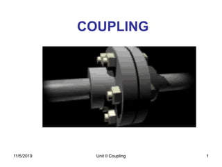
  • 1. 11/5/2019 Unit II Coupling 1 COUPLING
  • 2. 2 Coupling • Shafts are usually available up to 7 m length due to inconvenience in transport. In order to have a greater length, it becomes necessary to join two or more pieces of the shaft by means of a coupling. • A Coupling can be defined as a mechanical device that rigidly joins two rotating shafts to each other. • Uses:-  To Provide connections of shafts  To provide mechanical flexibility for misalignment of shaft  To reduce transmission of shock loads from one shaft to another shaft.  To introduce protection against overloads. 11/5/2019 Unit II Coupling
  • 3. Unit II Coupling 3 Types of coupling 1. Rigid coupling- to connect two shafts which are perfectly aligned. (a) Sleeve or muff coupling (b) Clamp or compressive coupling (c) Flange coupling 2. Flexible coupling- to connect two shafts having both lateral and angular misalignment. (a) Bushed pin coupling (b) Universal coupling (c) Oldham coupling 11/5/2019
  • 4. 11/5/2019 Unit II Coupling 4
  • 5. Unit II Coupling 5 1. Sleeve or Muff coupling 11/5/2019 Problem 1. Design a muff coupling which is used to connect two steel shafts transmitting 25 kW power at 360 rpm. The shafts and key are made of plain carbon steel 30C8 (Syt=Syc= 400N/mm2). The sleeve is made of grey cast iron FG 200 (Sut= 200 N/mm2). The factor of safety for the shafts and key is 4. For sleeve the factor of safety is 6 based on ultimate strength. Nov-Dec 2016, April May- 2013
  • 6. Unit II Coupling 6 Design of sleeve or muff coupling 1. Design for shaft: find diameter of the shaft using equation 2. Design for sleeve: • Find outer dia. of sleeve using relation D = 2d +13 mm & L= 3.5 d • Check induced shear stress in the sleeve using equation Where Mt = Torque to be transmitted by the coupling τ = Permissible shear stress for the material of the sleeve which is cast iron 3 1660 2 t t MP M and n d        44 16 dD DMt     11/5/2019
  • 7. Unit II Coupling 7 Cont… 3. Design for key:  For Parallel (rectangular and square sunk) keys • Refer Data book page no. 5.16 and select width(b) and height (h) of the key for given shaft diameter (d). • Length of the coupling key = 3.5 d length of the key in each shaft l = L/2 = 3.5d/2  Check for shearing and crushing stress (considering shear of key) (considering crushing of key) 2 tM dbl   4 t c M dhl   11/5/2019
  • 8. 11/5/2019 Unit II Coupling 8 Data Book page No. 5.16 DIMENSIONS OF PARALLEL KEYS AND KEYWAYS
  • 9. Unit II Coupling 9 Problem 1. Design a muff coupling which is used to connect two steel shafts transmitting 25 kW power at 360 rpm. The shafts and key are made of plain carbon steel 30C8 (Syt=Syc= 400N/mm2). The sleeve is made of grey cast iron FG 200 (Sut= 200 N/mm2). The factor of safety for the shafts and key is 4. For sleeve the factor of safety is 6 based on ultimate strength. Nov-Dec 2016, April May- 2013 11/5/2019
  • 10. Unit II Coupling 10 Problem 2. Design a rigid muff coupling. Use CI for the muff. The power transmitted is 25 kW at 300 rpm. Ultimate tensile strength =200 MPa and factor of safety =6. Use 30C8 for the shaft considered. Yield Point stress = 330 Mpa and factor of safety =4. (April-May 2012, Nov- Dec 2013) 11/5/2019
  • 11. Unit II Coupling 11 Problem 3. Design and make a neat dimensioned sketch of a muff coupling, which is used to connect two steel shafts transmitting 40 kW at 350 rpm. The material for the shaft and key is plain carbon steel for which allowable shear and crushing stresses may be taken as 40 MPa and 80 MPa respectively. The material for the muff is cast iron for which the allowable shear stress may be assumed 15 MPa. (Nov-Dec 2012) 11/5/2019
  • 12. Unit II Coupling 12 2. Clamp or compression coupling (split muff coupling) 11/5/2019
  • 13. Unit II Coupling 13 Dimensions for clamp coupling  For sleeve halves, Outer diameter of the sleeve D= 2.5 d, Length of the sleeve L= 3.5 d  For clamping bolts, Diameter of the claming bolt may be find out either 1. By using empirical equations: d1= 0.2 d + 10 mm (when d< 55 mm) And d1= 0.15 d + 15 mm (when d> 55 mm) or 2. By using following equations: (assuming that power is transmitted by friction) Where P1 = Tensile force on each bolt d1 = core diameter of clamping bolt n = total no. of bolts & f= coefficient of friction 2 1 1 1 2 4 t t M P and P d fdn    11/5/2019
  • 14. Unit II Coupling 14 Design Procedure Step 1. Calculate the diameter of each shaft. Step 2. Calculate the main dimensions of the sleeve halves. Step 3. Determine the standard cross-section of flat key from data book page no. 5.16. Length of the key in each shaft l = L / 2 = 3.5 d / 2 check the shear stress and compressive stress by using, and Step 4. calculate the diameter of clamping bolts by using 2 tM dbl   4 t c M dhl   2 1 1 1 2 4 t t M P and P d fdn    11/5/2019
  • 15. Unit II Coupling 15 Problem 1. It is required to design a split muff coupling to transmit 50 kW power at 120 rpm. The shafts, key and coupling bolts are made of plain carbon steel 30C8 (Syt= 400 N/mm2). The yield strength in compression is 150% of tensile yield strength. The factor of safety for shafts key and bolts is 5. The number of clamping bolts is 8. The coefficient of friction between sleeve halves and the shaft is 0.3. (i) Calculate the diameter of input and output shaft. (ii) Specify length and outer diameter of sleeve halves. (iii) Find out the diameter of clamping bolts assuming that the power is transmitted by friction. (iv) Specify bolt diameter using standard empirical relations. (v) Specify the size of key and check the dimensions for shear and compression criteria. 11/5/2019 April-May 2017
  • 16. Unit II Coupling 16 Problem 2. design a clamp coupling to transmit 30 kW at 100 rpm. The allowable shear stress for the shaft and key is 40 MPa and the number of bolts connecting the two halves are six. The permissible tensile stress for the bolts is 70 MPa. The coefficient of friction between the muff and the shaft surface may be taken as 0.3. 11/5/2019
  • 17. Unit II Coupling 17 3. Rigid flange coupling (A) Unprotected type flange coupling (B) Protected type flange coupling 11/5/2019
  • 18. Advantages:- 1.High torque transmitting capacity 2.Easy to assemble and dismantle. 3.Simple construction, easy to design and manufacture. Disadvantages:- 1.Does not tolerate misalignment. 2.Unsuitable for shock and vibration. 3.Requires more radial spaces. Unit II Coupling 1811/5/2019
  • 19. Unit II Coupling 19 Protected type flange coupling 11/5/2019
  • 20. Unit II Coupling 20 Dimensions for protected type flange coupling • Outside diameter of hub dh= 2d • Length of hub or effective length of key lh = 1.5 d • Pitch circle diameter of bolts D= 3d • Thickness of flanges t = 0.5 d • Thickness of protective rim t1 = 0.25 d • Diameter of spigot and recess dr = 1.5 d • Outside diameter of flange Do= 4d+2t1 • Number of bolts = 3, for d < 40 mm = 4, for 40 ≤ d <100 mm = 6, for 100 ≤ d < 180 mm 11/5/2019
  • 21. Design of flange coupling Unit II Coupling 21 1. Shaft diameter find diameter of the shaft using equations 3 1660 2 t t MP M and n d       11/5/2019
  • 22. Unit II Coupling 22 2. Dimensions of flange: dh= 2d lh = 1.5 d D= 3d t = 0.5 d  Check for torsional shear stress in the hub:-  Check for shear stress in the flange at the junction with the hub:- t1 = 0.25 d dr = 1.5 d Do= 4d+2t1 td M h t 2 2     4 4 32 2 ht h d dM r d where J and r J       11/5/2019
  • 23. 3. Diameter of bolts: Number of bolts N= 3, for d < 40 mm N= 4, for 40 ≤ d <100 mm N= 6, for 100 ≤ d < 180 mm diameter of bolt is determined by using equation:- Check compressive stress in bolt:- Unit II Coupling 23 DN M d t82 1  tDNd Mt c 1 2  11/5/2019
  • 24. 11/5/2019 Unit II Coupling 24 THREADS FOR BOLTS AND NUTS COARSE AND FINE SERIES
  • 25. Unit II Coupling 25 4. Design for key:  For Parallel (rectangular and square sunk) keys • Width X height (b x h) of the key:- Refer PSG Data book page no. 5.16 • length of the key in each shaft l = lh = 1.5 d  Check shearing and crushing stress 2 tM dbl   4 t c M dhl   11/5/2019
  • 26. Unit II Coupling 26 Problem 1. Design a cast iron protective type flange coupling to transmit 15 kW at 900 rpm from an electric motor to a compressor. The service factor may be assumed as 1.35. The following permissible stresses may be used: Shear stress for shaft, bolt and key material = 40 MPa Crushing stress for bolt and key = 80 MPa Shear stress for cast iron = 8 MPa Draw also a neat sketch of the coupling. (April May 2015, Nov-Dec 2013) 11/5/2019
  • 27. Unit II Coupling 27 Problem 2. Design and draw a protective type of cast iron flange coupling for a steel shaft transmitting 15 kW at 200 rpm and having an allowable shear stress of 40 MPa. The working stress in the bolts should not exceed 30 MPa. Assume that the same material is used for shaft and key and that the crushing stress is twice the value of its shear stress. The maximum torque is 25% greater than the full load torque. The shear stress for cast iron is 14 MPa. (2008 Supp.) 11/5/2019
  • 28. Unit II Coupling 28 Problem 3. Two 35 mm shafts are connected by a flanged coupling. The flanges are fitted with 6 bolts on 125 mm pitch circle diameter of bolts. The shaft transmit a torque of 800 N-m at 300 rpm. For the safe stresss mentioned below calculate: (i) diameter of bolts (ii) thickness of flanges (iii) Key dimensions (iv) hub length and (v) Power transmitted Safe shear stresses for shaft material = 63 MPa, Safe shear stress for bolt material = 56 MPa, safe shear stress for cast iron coupling = 10 MPa, Safe shear stress for key material = 46 MPa Also draw the line sketch of flange coupling. (Nov-Dec 2011) 11/5/2019
  • 29. Unit II Coupling 29 Problem 4. A rigid flange coupling is used to transmit 15 kW power at 720 rpm between two steel shaft. The shaft key and bolt are made of plain carbon steel 30C8 (Syt= 400 N/mm2), FOS= 3. The yield strength in compression may be taken as 150 % of tensile yield strength. The flanges are made of grey cast iron of grade FG200 (Sut= 200 N/mm2), FOS= 6. The keys have square cross section. Design a coupling and specify the dimensions of its part. 11/5/2019
  • 30. Unit II Coupling 30 Problem 5. A rigid flange coupling is required to transmit 50 kW at 300 rpm. There are six bolts. The outer diameter is of flange is 200 mm and diameter of recess is 150 mm. The coefficient of friction between the flanges is 0.15. The shaft and bolt are made of plain carbon steel 45C8 (Syt= 380 N/mm2), fos= 3. Determine the diameter of the bolts. Assume that the bolts are set in large clearance holes. 11/5/2019
  • 31. 11/5/2019 Unit II Coupling 31 (April-May 2016)
  • 32. 11/5/2019 Unit II Coupling 32 (April-May 2015)
  • 33. 11/5/2019 Unit II Coupling 33 (Nov-Dec 2015)
  • 34. 11/5/2019 Unit II Coupling 34 (Nov-Dec 2014)
  • 35. Unit II Coupling 35 4. Bushed-pin flexible coupling 11/5/2019
  • 36. 36 Step 1. Shaft diameter:- Step 2 . Dimension of flange:- • dh= outside diameter of hub= 2d • lh= length of hub or effective length of key = 1.5d • D= pitch circle diameter of pins= 3d to 4d • t= thickness of output flanges = 0.5d • t1= thickness of protective rim= 0.25d • The torsional shear stress in the hub is given by- Design procedure for flexible coupling  4 4 32 2 ht h d dM r d where J and r J       11/5/2019 Unit II Coupling
  • 37. Unit II Coupling 37 • The shear stress in the flange at the junction with the hub is given by:- Step 3. Dimensions of bushes:- • Outer diameter of rubber bush (Db) is determined from the equation. • Where pm is pressure between bush and C.I. flange (usually 1N/mm2 ) • Effective length of the rubber bush lb= Db Step 4. Diameter of Pins:- • Diameter of pins , Number of pins (n) is usually 4 or 6. • Determine the shear stress in the pins by, 11/5/2019 td M h t 2 2   
  • 38. Unit II Coupling 38 Step 5. Check for bending stress in pins:  Torque transmitted by the coupling: From above equation force P on each rubber bush or pin is determined.  Bending moment on the pin is given by:  Bending stress is checked by equation: 11/5/2019
  • 39. Unit II Coupling 39 Step 6. Dimensions of keys:  Determine the standard cross-section of flat key from data book page no. 5.16.  Length of the key l = length of hub = lh =1.5d  check the shear stress and compressive stress by using, 2 tM dbl   4 t c M dhl   11/5/2019
  • 40. Unit II Coupling 40 Problem 1. A bushed pin type flexible coupling is used to connect two shafts and transmit 5 kW power at 720 rpm. Shafts, keys and pins are made of commercial steel (Syt=Syc=240 N/mm2) and the factor of safety is 3. The flanges are made of grey cast iron FG200 (Sut= 200 N/mm2) and the factor of safety is 6. Assume Ssy=0.5 Syt and Ssu= 0.5 Sut There are 4 pins. The pitch circle diameter of the pins is four times of shaft diameter. The permissible shear stress for pins is 35 N/mm2. The bearing pressure for rubber bushing is 1 N/mm2. The keys have square cross section. Calculate: (i) diameter of the shafts (ii) dimensions of flange and hub (iii) dimensions of the key (iv) diameter of the pins (v) outer diameter and effective length of the bushes. 11/5/2019
  • 41. Unit II Basic Elements Design 41 Assignment-2 Que.1 Design a Knuckle joint (with fork and eye) to with stand a load of 10,000 N. The materials used for all components have the following properties ultimate tensile strength = ultimate compressive strength = 480 N/mm2. Shear strength = 360 N/mm2. Factor of safety =6. After design, draw a neat proportioned sketch of joint giving all dimensions. Que.2 Design a cotter joint to carry a maximum load of 50,000 N. All components are made of the same material having the following allowable stresses. (Sleeve and cotter joint) Tensile stress = 20 MN/m2 Compressive stress = 50 MN/m2 Shear stress = 15 MN/m2 Draw a proportioned neat sketch of the joint you have designed. Que.3 It is required to design a square key for fixing a pulley on the shaft which is 50 mm in diameter. A 10 kW power at 200 r.p.m. is transmitted by the pulley to the shaft. The key is made of steel 45C8 (Syt= Syc= 380 N/mm2) and the factor of safety is 3. Determine the dimensions of the key. 11/5/2019
  • 42. 42 Que. 4 Design a C.I. flange coupling to transmit 150 H.P. at 250 rpm. The following permissible stresses may be used: Permissible shear stress for shaft, bolt and key material = 50 N/mm2 Permissible crushing stress for bolt and key material = 150 N/mm2 Permissible shear stress for Cast iron = 8 N/mm2 (Nov-Dec 2010) Que.5 It is required to design a bushed pin type of flexible coupling for connecting the motor to a centrifugal pump shafts. The details of the duty required from the pump are: Power to be transmitted = 18.5 kW Speed in rpm = 1000 The diameters of the motor and pump shafts are 50 mm and 45 mm respectively. Take the bearing pressure on the rubber bush as 0.35 N/mm2 and the working shear stress in the material of the pins as 20 N/mm2. (2009) 11/5/2019 Unit II Coupling