Más contenido relacionado
La actualidad más candente (19)
Similar a Ulan Bator_preliminary project (20)
Ulan Bator_preliminary project
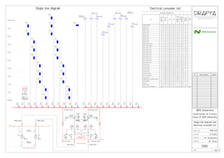
- 1. Voltage range: 380V
Frequency: 50Hz
Grounding system type: TN-C-S
QF1 QF2
QF1 QF2
PEN
QF1.1
63
63A
Power input panel 1 Power input panel 2
Wh Wh 2LS12QF21LS1 1QF1
ATS
control
I II
ATS
control
III
1QF1 1QF2
1SF3
1HL11KV1
1SF4 2SF3
1HL1 1KV1
2SF4
Feeder cable 1
2QF1 2QF2
QF1.2
63
32A
QF2.1
63
25A
QF2.2
63
63A
Main Switchboard
Distribution panel 2
Outdoor power substation
NPE N PE
Feeder cable 2
Distribution panel 1
L1,L2,L3
N
PE
LP0.1
Basement
1 floor
2 floor
3 floor
4 floor
5 floor
6 floor
7 floor
8 floor
LP1.1
LP2.1
LP3.1
LP4.1
QF1.3
63
32A
QF1.4
63
32A
LP6.1
LP7.1
LP5.1
9 floor
Technical floor
LP9.1
LP10.1
LP8.1
Feeder cable 1 Feeder cable 2
QF1.5
63
32A
QF1.6
63
32A
PP0.1
PP1.1
PP2.1
PP3.1
PP4.1
QF1.7
63
32A
QF1.8
63
32A
PP6.1
PP7.1
PP5.1
PP9.1
PP8.1
Elevator's
Control panel
QF2.3
63
32A
QF2.4
63
10A
PP9.2
QF1.9
63
32A
QF2.5
63
20A
QF2.6
63
10A
QF1.11
63
32A
1 2 3 4
L1,L2,L3
N
PE
QF1.10
63
10A
5
Control panel
10, 11
Control panel
2
Control panel
1
Control panel
1, 2
Control panel
9
Control panel
3
Control panel
4
Control panel
QF2.6
63
20A
QF2.6
63
10A
QF2.6
63
10A
QF2.6
63
32A
Electrical consumer list
Title
Connect
ed
power-
,
kW
Utilizati
on
factor-
Consum
ed
power
=
* ,
kW
Reactiv
e power
Q = *
kVAr
Total
power
S =
Fixed
current
,
Lighting Basement 2.8 1.00 0.92 0.43 2.77 1.18 3.01
Lighting 1 floor 4.3 1.00 0.92 0.43 4.32 1.84 4.7
Lighting 2 floor 3.7 1.00 0.92 0.43 3.74 1.59 4.07
Lighting 3 floor 3.8 1.00 0.92 0.43 3.78 1.61 4.11
Lighting 4 floor 3.7 1.00 0.92 0.43 3.67 1.56 3.99
Lighting 5 floor 3.8 1.00 0.92 0.43 3.78 1.61 4.11
Lighting 6 floor 3.6 1.00 0.92 0.43 3.64 1.55 3.95
Lighting 7 floor 3.6 1.00 0.92 0.43 3.64 1.55 3.95
Lighting 8 floor 3.0 1.00 0.92 0.43 3.02 1.29 3.29
Lighting 9 floor 3.5 1.00 0.92 0.43 3.46 1.47 3.76
Lighting Technical floor 0.5 1.00 0.92 0.43 0.47 0.20 0.51
Power system Basement 4.7 0.40 0.60 1.33 1.87 2.50 3.12
Power system 1 floor 8.5 0.40 0.60 1.33 3.41 4.54 5.68
Power system 2 floor 3.7 0.40 0.60 1.33 1.49 1.98 2.48
Power system 3 floor 3.7 0.40 0.60 1.33 1.49 1.98 2.48
Power system 4 floor 1.9 0.40 0.60 1.33 0.76 1.01 1.26
Power system 5 floor 0.5 0.40 0.60 1.33 0.19 0.26 0.32
Power system 6 floor 2.4 0.40 0.60 1.33 0.95 1.26 1.58
Power system 7 floor 2.4 0.40 0.60 1.33 0.95 1.26 1.58
Power system 8 floor 1.6 0.40 0.60 1.33 0.64 0.85 1.06
Power system 9 floor 0.6 0.40 0.60 1.33 0.25 0.34 0.42
1 Control panel 27.3 0.80 0.80 0.75 21.84 16.38 27.3
2 Control panel 9.6 0.80 0.80 0.75 7.68 5.76 9.6
3 Control panel 2.8 0.80 0.80 0.75 2.24 1.68 2.8
4 Control panel 7.0 0.80 0.80 0.75 5.6 4.20 7
5 Control panel 2.3 0.80 0.80 0.75 1.84 1.38 2.3
1, 2 Control panel 8.3 0.80 0.80 0.75 6.64 4.98 8.3
10, 11 Control panel 2.6 0.80 0.80 0.75 2.08 1.56 2.6
9 Control panel 1.1 0.80 0.80 0.75 0.88 0.66 1.1
3- 8(supplied from lighting system) 0.6 0.80 0.80 0.75 0.48 0.36 0.6
Cafe's equipment 27.2 0.80 0.90 0.48 21.76 10.54 24.18
Elevators 9.0 0.80 0.80 0.75 7.2 5.40 9
Outdoor lighting 1.0 1.00 0.80 0.75 1 0.75 1.25
Total load of the switchboard: 165.06 0.77 0.83 0.67 127.52 85.09 153.3 232.91
Scale
Checked by
Drafted by
Issue date
Project code
Single line diagram and
electrical consumer list
MON-C69
Construction of 9-story
Corps of IDER University
IDER University
21.11.2014
Mr. Stanislavov
Mr. Titkov
1 : 100
11/16/14
E002
# Description Date
Electrical consumer listSingle line diagram
- 2. Basement floor schedule
Name Area, sq.m Notes
LP0.1
3
1
600012000
002
001005
004
1
1(14)
2
6000 6000
006
003
12000
1800600060006000
-3.300
008
007
-3.300
2
2
001 Elevator shafts 6.22
002 Stairs 16.51
003 WC 7.74
004 Additional technical room 4.03
005 Boiler room 21.73
006 Computer Repair Shop 147.31
007 Switchboard 4.55
008 Communication mine 6.08
0.4kV feeder
cable from an
outdoor power
substatioin
Protective
non-metallic
tubing
3045
600012000
002
001005
004
1
1(14)
2
2(14)
6000 6000
006
003
12000
1800600060006000
-3.300
008
007
-3.300
PP0.1
Input power
panel
Distribution
panel
Boiler's
control panelsupply for
Sololift2 WC-3
Grounding
Symbol:
Cable placed in cable tray above suspended ceiling
Cable placed in non-metallic tubing consealed in floor
Switchboard
PP-Power panel
CP-Control panel
Emergency lighting panel
Floor outlet box
Power pole
Lighting fixture - OPL/R ECO
Lighting fixture - DLG 218
Lighting fixture - ARCTIC SAN/SMC 218
Lighting fixture - CD 218
Wall installation
Emergency lighting fixture
Electrical socket 220V
Electrical socket 2x220V
Electrical socket 3x220V
LP-Lighting panel
Junction 380V from below (to supply electrical
equipment to junction box, leave 1,5m of spare cable)
Junction 220V from below (to supply electrical
equipment to junction box, leave 1,5m of spare cable)
Description:
Grounding network on walls
Scale
Checked by
Drafted by
Issue date
Project code
Basement- lighting and
power systems
MON-C69
Construction of 9-story
Corps of IDER University
IDER University
21.11.2014
Mr. Stanislavov
Mr. Titkov
1 : 100
11/16/14
E003
# Description Date
1 : 100
Basement- Power system
1 1 : 100
Basement- Lighting system
2
- Vertical grounding rod
- Groundind network in earth