AXPERT-i-sine is designed with the intelligent control algorithm which dynamically changes the switching frequency to optimize the performance & efficiency. The performance of AXPERT-i-sine is less affected by supply voltage harmonic distortion. AXPERT-i-sine provides selective harmonic attenuation up to 51st order.
Apidays Singapore 2024 - Building Digital Trust in a Digital Economy by Veron...
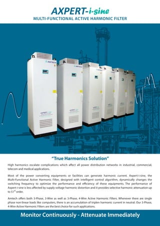
Axpert i-sine - Multi Function Active Harmonic Filter
1. High harmonics escalate complications which affect all power distribution networks in industrial, commercial,
telecom and medical applications.
Most of the power converting equipments or facilities can generate harmonic current. Axpert-i-sine, the
Multi-Functional Active Harmonic Filter, designed with intelligent control algorithm, dynamically changes the
switching frequency to optimize the performance and efficiency of these equipments. The performance of
Axpert-i-sine is less affected by supply voltage harmonic distortion and it provides selective harmonic attenuation up
to 51st
order.
Amtech offers both 3-Phase, 3-Wire as well as 3-Phase, 4-Wire Active Harmonic Filters. Whenever there are single
phase non-linear loads like computers, there is an accumulation of triplen harmonic current in neutral. Our 3-Phase,
4-Wire Active Harmonic Filters are the best choice for such applications.
Monitor Continuously - Attenuate Immediately
“True Harmonics Solution”
AXPERT-i-sine
MULTI-FUNCTIONAL ACTIVE HARMONIC FILTER
2. AXPERT-i-sine provides 3-Phase harmonic current compensation. Figs. 1 and 2
show the operational principle of the active filter, with which a rectifier load is
connected.
As shown in Fig. 1, the active filter is inserted between the load and the source, in
parallel to the load. For a six-phase rectifier load, the load current IL appears in a
form of rectangular waves, as illustrated in Fig. 2. This can be considered a result
of synthesis of the fundamental current IF and the harmonic current IH (Fig. 2).
(IL = IF +IH)
The compensation current IC of the active filter is controlled, so that its intensity is
the same as that of the above-mentioned IH and its polarity is just reversed (IC = -IH).
As a result, components of harmonic currents in the load current are cancelled by
the effect of active filter and source current IS remains only to IF, which is a
sinusoidal wave (Fig. 2).
This can be clearly explained by the expression below:
Axpert-i-sine is equipped with a user-friendly control panel. Self-explanatory full
parameter names, easy navigation of parameters through well organized
parameter sets and functional keys with 8-selectable parameters on single screen
make it easy to operate and program.
The optional TFT panel with special white back light offers access to all parameters,
waveforms and spectrums for management of both Axpert-i-sine and system power
quality.The graphicsTFT display and control panel give easy access to:
Load, source & Axpert-i-sine
Monitoring of all metering parameters like V, I, F, kVA, PF, THD
Control commands & settings
Waveforms & harmonics spectrum (optional touch screen TFT panel)
Status & alarms
IS
IF
IL
Axpert i-sine
Fig. 1
Fig. 2
a. IL
( IF + IH)
( = -IH)
( = IF)
IF
b. IH
c. IC
d. IS
Standard LCD Display
Optional Touch Screen TFT Panel
IL = IF +IH, IC = -IH
IS = IL + IC = (IF +IH) + (-IH) = IF
Fast Fourier transform based harmonic compensation
Operates with closed loop control
Reactive power compensation
Ability of parallel operation to increase power capacity
Voltage-independent harmonic current tracking
Inherent current limiting
Shunt connection
Backlit user interface (optional TFT with touch screen)
Modbus RTU communication compatible
Advanced programmable digital I/O interface
Intelligent control algorithm which dynamically changes
the switching frequency to optimize the performance
Programmable selective harmonics elimination Prevents
possible harmonic resonance
Best accuracy. Does not require detailed network analysis
Automatic PF compensation, leading as well as lagging,
optimum utilization of power capacity and reduction in kVA
demand
Adaptive to increase in harmonics current due to additional
loads being added
More immunity to input voltage distortion
Overload condition is prevented
Easy maintenance
User-friendly operation
Facilitates networking ability and remote monitoring
Selective harmonics elimination by digital programming
Minimum insertion loss resulting in efficient operation
FEATURES BENEFITS
Monitoring & Signaling
Principle of Harmonics Suppression
Why i-Sine Active Harmonic Filter?
AXPERT
NORM MODE
AMTECH
GROUP
ENTER
UP
DOWN
FAUL T
RUN
STOP
Active Harmonic Filter
RESET
No rm
4 1 5 V r y 50 . 0 l R S
4 16 V y b 25 .0 l R F
Lc l , N o r m a l R u n
3. Heat loss (Watt)
Input power source (1)
Max. peak filter current (Apk)
Filter current in phase IF (Arms)
Control method Digital Fast Fourier Transform with Hysteresis current control
Harmonic filtering Harmonics orders up to 51st
Harmonic order selection Global / Selective compensation from 3rd
to 51st
order with settable amplitude
Harmonic attenuation ratio (5)
Better than 97% at rated current
P. F. improvement | Load balancing Automatic P. F. improvement up to the unutilized capacity of filter | Load balancing between line-to-line
Voltage -15% to 10%, Frequency ±5%
Max. switching frequency 18 kHz
78 uSec msReaction time
Operation Specifications
Digital inputs 5-Programmable sequence inputs, sink / source changeable
Digital outputs 4-Programmable sequence outputs, open collector type
Programmable analog outputs 2-Programmable analog current outputs IO1 & IO2: 4 ~ 20mA
Soft-charge Through resistor within 5 sec.
Auto start Yes, AHF can start at power ON condition in local and serial mode
Auto restart Adjustable up to ten times for faults like over current fault, timed over current fault, adjustable over current fault,
DC bus over voltage fault, DC bus under voltage fault, earth fault, over temperature fault and external fault with
individual enable and disable
Potential free contacts 3-Programmable relays with 1-NO, 1-NC for 5A @ 240 VAC
Programmable between 12 different options
030
30
75
≤1200
060
60
145
≤2000
100
100
240
≤3000
150
150
360
≤5000
200
200
480
≤6100
300
300
720
≤7000
Standard Specifications
Fault history Last ten faults - with status at time of fault - are stored in memory
Electronic thermal overload 120% overload for 60 seconds, above 100% harmonic current is limited by software
Network connectivity RS-485 for PC interface with Modbus-RTU protocol as standard (Profibus-DP (slave), DeviceNet, CANopen,
Ethernet, ControlNet are optional)
TFT module (optional) TFT Touch screen graphical display
Display current waveform of Filter / Load / Source side for each phase
Display and keypad module Total 80-Character, 4-Line LCD panel, 8-Key keypad, 3-Status indicating LED for Run, Stop and Fault
THDv, Line frequency, DC bus voltage, PF, DPF, kW, kVA, kVAR, VL-L
Current of Filter / Load / Source side for each phase, THDi of Load and Filter side
AMT-AHF-XXX-4/5-1N (2, 3 & 4)
1. Products for 60 Hz power supply frequency are also available on request.
2. Above 300A requirement, multiple units will be connected in parallel. Up to 40 units can be connected in parallel. Contact Amtech for any other requirement and more details.
3. The -4 is for 415 input supply and -5 is for 600V supply.
4. The - 1N in the part number defines the neutral current capacity equal to the rated filter current; For higher neutral current rating, consult Amtech. This is only applicable for the 3-Phase, 4-Wire system.
5. Minimum 3 % line reactor is required in series with higher di/dt load.
6. All performance specifications are valid at nominal ratings.
200
200
480
≤6250
150
150
360
≤5150
100
100
240
≤3100
060
60
145
≤2100
Electrical
Control Functions
Display Indications
Communication
Installation location Indoor (consult Amtech for outdoor applications)
Type of cooling Forced air cooling
Ambient temperature 0o
°C (32o
°F) ~ 40o
°C (104o
°F)
Storage temperature -20o
°C (-4o
°F) ~ 70o
°C (158o
°F)
Audible noise <72dB @1 m (3.28 ft)
Humidity 0 ~ 95% maximum, non condensing
Color RAL 7035
Harmonic IEEE 519-1992, G5/4-1, GB/T 14549-93, IEC 61000-3-2, IEC 61000-3-4
Safety IEC 50178
Protection class IP 31 (consult Amtech for higher protection requirements)
Installation A = Wall/Floor mounting, B, C = Floor mounting
Dimensions (W X DX H) in mm [inch]
Dimensions A A B B C C B B B C B C C C
Approximate weight in kg [lb]
Altitude (above sea level) 1000 m (3300 ft) w/o derating, [derate 1% per 100 m (330 ft) above 1000 m (3300 ft)]
Model derating with temperature Above 40o
°C (104o
°F), derate the output current by 3% /1o
°C (1.8o
°F)
Maximum up to 55o
°C (131o
°F) temperature
80
[176.4]
90
[198.4]
272
[599.6]
280
[617.3]
350
[771.6]
430
[948]
251
[553.4]
280
[617.3]
320
[705.5]
422
[930.3]
A = 480 X 370 X 1065
[18.9 X 14.6 X 42]
B = 600 X 600 X 1960
[23.6 X 23.6 X 77.2]
C = 800 X 600 X 2160
[31.5 X 23.6 X 85.04]
Environment
Mechanical Specifications
Reference Standard
Protective Specifications
100
100
280
<4300
150
150
360
<6000
200
200
480
<8000
220
220
530
<8500
415 VAC, 3-Phase, 3-Wire, 50 Hz 415 VAC, 3-Phase, 4-Wire, 50 Hz 600 VAC, 3-Phase, 3-Wire, 50 Hz
275
[606.3]
360
[793.7]
470
[1036]
470
[1036]
Transient response time Less than one power cycle ms
Protective function 1. Over current 7. Phase loss
2. Adjustable over current 8. Ground fault
3. Timed over current 9. External fault
4. DC bus over voltage 10. Charging fault
5. DC bus under voltage 11. EEPROM fault
6. Over temperature 12. CT Detection fault
Operational Specification