SlideShare una empresa de Scribd logo
1 de 6
Descargar para leer sin conexión
DIGITAL TEMPERATURE
ADJUSTMENT SYSTEMS    DESCRIPTION
TYPE 354              These electronic systems are suitable for temperature
                      control in closed-chamber or open-chamber wall hung
WITH REMOTE CONTROL   boilers fitted with atmospheric gas burners.

BOARD TYPE 364        GENERAL FEATURES
                      Temperature adjustment systems are usually manufactured
                      on customer's request according to the type of boiler, the
                      components used and the operation specifications. In
                      general, these systems are provided with the following
                      features:
                      − single electrode or double electrode ignition and flame
                          monitoring (ionisation) system fitted with remote ignition
                          device;
                      − control of the boiler parts (pump, fan, deflection valve,
                          flow switch, air pressure switch, thermostats, etc.);
                      − controls, adjusters and signals on a remote control
                          board connected to the mother board by means of a
                          bipolar cable (length up to 20 m);
                      − use of contact or immersion probes for temperature
                          measurement, exploiting the resistivity characteristic of
                          NTC components;
                      − temperature adjustment function control by means of a
                          microcontroller;
                      − 4kV and 8mm SELV (Safety Extra Low Voltage)
                          insulation on the printed circuit board surface between
                          components connected to the mains supply and low
                          voltage controls;
                      − flame modulation by means of a proportional, integral
                          and derivative (PID) electronic system;
                      − differentiated setting of the required water temperature
                          for heating and domestic hot water operation mode;
                      − adjustable setting of the boiler max. heat capacity in
                          heating mode;
                      − domestic mode priority by means of a (power-driven or
                          hydraulic) three-way valve or a flowmeter;
                      − pump overrun and lockout prevention and deflection
                          valve lockout prevention;
                      − antifreeze function;
                      − cancellation of the heat demand in case of interruption
                          of the signal emitted by temperature measuring probes;
                      − fixed safety limit of the boiler primary hydraulic circuit
                          temperature;
                      − connection to a safety limit thermostat;
                      − prearranged for use in floor heating systems;
                      − prearranged for use with LPG or natural gas;
                      − diagnostic functions: heat demand signal, boiler lockout,
                          probes cut-off, lack of water in the system, lack of stack
                          draft;
                      − EMC system.


4087_r01                                                                         1/6
TECHNICAL DATA                                                     −    The appliance in which this temperature adjustment
Supply voltage:                              230V-50/60Hz               system is mounted must provide adequate protection
Operating temperature range:                 -20°C +60°C                against the risk of electric shock (at least IP 20).
Humidity:                                 95% max. at 40°C         −    Avoid placing control signal cables close to power
Protection degree:                                   IP 00              cables.
Dimensions:                                 140x100x44mm
                                                                   INTEGRATED TEMPERATURE ADJUSTMENT SYSTEM
                                                                   Integrated temperature adjustment systems are usually
CONSTRUCTION                                                       manufactured on customer's request as far as operation
The system consists of three units (electronic boards):            and control of the boiler parts are concerned. For a more
a) Mother Board (SM), which houses the boiler control              detailed description, we will refer to a particular type, the
      and the connections to the remaining components;             main features of which are shown in Fig. 2. The integrated
b) Ignition and Control Module (ACF): this board,                  temperature adjustment system we are going to consider
      carrying out the burner safety functions, can control a      consists of the following components:
      single electrode or double electrode system, and is
      mounted directly on the mother board by soldering,           -    Ignition and Control Module (ACF)
      thus reducing the number of wires on the power                    Timings:
      switchboard; the surface of this board is protected with
      epoxy resin to prevent possible damages resulting                - waiting or prepurge time (TW):                1,5 … 40 s
      from incautious handling or external agents such as              - safety time (TS):                               3 … 60 s
      dust or humidity;                                                - drop-out time on flame failure:                    <1s
c) Control Board (SC), on which adjustment controls
      (push-buttons) and diagnostic signals (on a display)             The above times correspond to guaranteed values.
      are mounted.                                                     Actual values may differ from declared ones, as waiting
The above units are fitted to a Remote Ignition Device                 or prepurge time may be longer and safety time shorter.
(AR) controlled by ACF, reducing electromagnetic
interference and enabling the system to fully comply with               -    Power consumption, start-up:
electromagnetic compatibility standards without using any
                                                                        - open chamber                     18VA
filters. (for technical characteristics, see our data sheets
                                                                        - closed chamber                   20VA
“REMOTE IGNITION TRANSFORMERS TYPE TR2”).
The use of non-reversible connectors with a different
                                                                        -    Power consumption, running:
number of poles makes connection easy and reliable. A
varistor protects the components from possible voltage                  - open chamber                     15VA
transients in the mains supply.                                         - closed chamber                   17VA
An inbuilt fuse protects the internal relays in case of short
circuit on the control outputs.                                         -    Max. contact rating: (contacts mounted on SM)

                                                                        - VG1 gas valve:                   0.5A    cos ϕ ≥ 0.4
ACCESSORIES                                                             - Fan:                             1A      cos ϕ ≥ 0.4

The system can be suppied with:                                         -    Max. cable length of
- connectors and terminals for wiring (see Fig.1);                           external components:          1m
- contact temperature probes (type ST03, ST04 and ST07);
- immersion temperature probes (type ST06 and ST09).                    -    Max. length of the cable
                                                                             connecting control board
For the technical characteristics of the probes, see relevant                and mother board:        20 m
data sheets.
As for the connectors, pay attention not to fit terminals and           -    Internal fuse:                3.15 A quick acting
female connectors of different brands.


                                                                   Flame monitoring:
                                                                      The flame detection device makes use of the
                                                                      rectification property of the flame; this device is not
      FEMALE CONNECTORS                 TERMINALS                     provided with any protection impedance, therefore the
        STOCKO: MKF 2800                STOCKO: RFB 7851              detection electrode is not safe against electric shock.
        STELVIO:BS95/...                STELVIO: CT84

                                                           Fig.1       - Min. ionisation current:                           0.5µA
                                                                       - Recommended ionisation current:            3÷5 times the
                                                                                                           min. ionisation current
DIRECTIONS FOR INSTALLATION                                            - Max. cable length:                                    1m
− Respect the applicable national and European                         - Min. insulation resistance of detection
   standards (e.g. EN60335-1/prEN50165) regarding                        electrode and cable to earth:                   ≥ 50 MΩ
   electrical safety.                                                  - Electrode max. stray capacitance:                  ≤ 1 nF
− Connect live and neutral correctly; the non-observance               - Max. short circuit current:                 < 200µA AC
   of live-neutral polarity may cause a dangerous situation.
− Before starting the system check the cables carefully; a
   wrong wiring can damage the devices and compromise
   the safety of the installation.
− Connect and disconnect the control system only after
   switching off the power supply.
− The system can be mounted in any position.
− Avoid exposing the system to dripping water.


2/6                                                                                                                       4087_r01
♦ MOTHER BOARD (SM)

-   Temperature measuring probes                                 -   External probe
    The system operates with one or two temperature                  The control board (SC) is prearranged for the
    measuring probes, depending on the type of boiler.               connection to an NTC sensor (similar to the one
    For boilers for heating only, the system only uses               used in temperature probes), which measures the
    the heating probe (SR), which is usually placed on               temperature outside the building in which the
    the output pipe of the boiler heat exchanger. For                installation is placed. The available adjustments for
    boilers for domestic hot water production, the                   the user in heating mode are the required room
    system also uses the domestic probe (SS), which is               temperature and the heat dispersion coefficient of
    usually placed on the output pipe of the domestic                the room walls. The temperature appearing on the
    circuit. In case of short circuit or cut-off of one of the       display is the temperature measured by the primary
    probes, depending on the type of boiler the                      circuit probe, and in running state it will have the
    temperature adjustment system can either operate                 same value as the set-point resulting from the
    with the remaining probe, signalling a failure, or               processing of the two preset parameters and the
    cancel any heat demand, preventing the boiler from               outside temperature. Upon variation in the latter
    operating.                                                       one, the primary circuit set-point changes
    The probe fitted to the heating circuit (SR) also                automatically to reach the preset room temperature.
    operates as limit thermostat, thus stopping any heat
    demand if the water temperature exceeds the preset
    limit temperature.

                                                                 Functions of the mother board

-   Safety thermostat                                            -   Setting functions during installation
    In general, the boiler is perfectly safe against                 During the boiler installation, some system functions
    possible overtemperature in the primary circuit: to              are usually set (see below), which are mainly related
    this purpose, a safety thermostat is used, which is              to the features of the system itself. Please note that
    connected to the mother board (SM) in series to the              these settings are only possible through the jumpers
    gas valve. The thermostat stops the gas flow and                 J16-19, therefore they cannot be carried out by the
    consequently extinguishes the flame; then a starting             user once the boiler has been closed.
    attempt occurs followed by non-volatile lockout.
    Before trying to start a new ignition cycle, reset the       -   Function of jumpers (Fig. 2)
    system manually.                                                 The mother board is provided with a number of
                                                                     jumpers to fit the temperature adjustment system to
                                                                     the final installation:
                                                                     J7 must be inserted for LPG systems;
- Air pressure switch (for closed-chamber boilers                    J16 in position 0: the user's normal functions
  only)                                                              (domestic hot water mode, heating mode,
  It checks the circulation of combustion products in
                                                                     summer/winter selection) are available on the
  the combustion chamber and allows boiler ignition
  only if the fan is operating and the draft is regular; it          control board (SC); if J16 is placed in position 1, the
  also ensures the boiler safety shutdown if one of                  parameters which are useful during setting can be
  these conditions fails during operation. Upon                      adjusted;
  request, in open-chamber boilers the air pressure                  J17 in position 0: it requires a delay of at least 2,5
  switch can be replaced by a combustion products                    min. between a turnoff and subsequent re-ignition in
  discharge safety device using the same connector.                  heating mode; if J17 is placed in position 1, re-
                                                                     ignition occurs as soon as the temperature drops of
                                                                     5°C below the preset value;
                                                                     J18 in position 0: it enables heat adjustment in
-   Water pressure switch / Pressure transducer
                                                                     traditional systems (variable from 30 to 80°C);
    It ensures that the primary circuit pressure is within           placed in position 1, it enables heat adjustment in
    the required operation range. In case the pressure
                                                                     floor heating systems (variable from 15 to 40°C);
    is too low, the temperature adjustment system stops              J19 in position 0: it adjusts domestic hot water
    any heat demand and the type of failure appears on               temperature from 30 to 60°C; placed in position 1, it
    the control panel. In case a pressure transducer is
                                                                     selects hot water tank boilers or boilers for heating
    used, the pressure level can be displayed on the
                                                                     only.
    control panel through 5 LEDs.


-   Water flow switch / Flowmeter
    The SM is provided with an input for the connection
    of either a water flow switch or a flowmeter
    signalling domestic water drawing. The deflection
    three-way-valve (if available) can be automatic
    (hydraulic) or electrically controlled by the system.


-   Room thermostat
    The room thermostat is connected on the remote
    control board (SC) by two wires; it is designed to
    operate with a contact isolated from the mains
    supply.
4087_r01                                                                                                                       3/6
♦ REMOTE CONTROL BOARD (SC) ( type 364 )                           OPERATING CYCLE

                          TA
                                                                   The following operating cycle refers to the temperature
                                                                   adjustment system described above.

                                                                   Starting cycle
                                                                   The starting cycle begins on heat demand by the room
              SIGN   0V
                                                                   thermostat (heating mode) or the water flow switch /
                                                                   flowmeter (domestic hot water mode). The water pump is
                                                                   energized, and if the water temperature is lower than the
                                     Led fiamma                    preset value, a burner starting demand will occur.
      L                                                      SW8
      EP                                                           In case of a closed-chamber boiler, the control unit starts
      DR
      S E
                                                                   the fan only if the air pressure switch is in "no-air-flow"
        S                                                          position; when it switches into "air-flow" position, the
      F S                                                    SW7
      AI
                                                                   prepurge time TW begins, at the end of which the gas valve
      S O                                                          is supplied, the ignition device is started and the safety time
      CN
      I E                                                          TS begins. In this stage, the burner heat capacity is kept at
      A                                                      SW6   a low value (slow ignition). If a flame signal is detected at
                                                                   the end of TS, the temperature adjustment process will
                                                                   begin, and the burner flame will be modulated in order to
                                                                   reach the same water temperature as the preset value.
                                                                   If no flame signal is detected within the safety time, on the
            SW3      SW4       SW1           SW2    SW5
                                                                   elapsing of TS the gas valve will close and lockout will
                                                                   occur. The boiler lockout is signalled on the control panel;
      The control board is fitted with the following: eight        to reset the system press the corresponding push-button.
      push-buttons (enabling the user to carry out any             If hot water demand still occurs, the boiler will start a new
      adjustment and setting during installation), two             ignition cycle; if the conditions leading to lockout still occur,
      displays (showing temperature, settings and failure          the boiler will go back to lockout. The boiler keeps on
      signals), a LED signalling flame on, and five LEDs           running until either heat demand stops, or one of the safety
      for system pressure indication (in case a pressure           devices switches on, or the flame extinguishes.
      transducer is available); pressure ranges can be
      customized through the software.
                                                                   Domestic hot water mode
-     Display                                                      Ignition demand in domestic mode has priority over heating
      The two-digit display usually shows the current              mode. The boiler burner ignition occurs when hot water is
      water temperature in heating or domestic mode;               drawn; the boiler will try and supply the user with domestic
      however, when pressing one of the push-buttons for           hot water at preset temperature (variable from 30 to 60°C).
      water temperature adjustment, the display shows              If the required capacity is lower than the min. modulation
      first the last preset temperature value and then the         capacity, the boiler will perform short ignition and turnoff
      current temperature setting.                                 cycles. If the required capacity is higher than the boiler
      If the adjustment functions required during                  max. capacity, the water temperature will be proportional to
      installation are recalled, the display shows a               the quantity of drawn water, but lower than preset
      percentage value indicating the adjustment level (0-         temperature.
      99%).

-     Functions of remote control board push-buttons               Heating mode
      The standard function of push-buttons with J16 in            If the boiler is in winter position, and on room thermostat
      position 0 is the following:                                 switching off the outgoing water temperature is lower than
            SW3 : heating set-point decrease                       the preset value, boiler ignition will occur and flame
            SW4 : heating set-point increase                       modulation will begin until the boiler reaches the running
            SW1 : domestic set-point decrease                      condition. If the outgoing water temperature is 5°C higher
            SW2 : domestic set-point increase                      than the value previously adjusted by the user (variable
            SW5 : Summer / Winter selection
                                                                   from 30 to 80°C), the boiler will switch off; re -ignition occurs
            SW6 : available for particular functions
            SW7 : boiler reset                                     as soon as the water temperature drops of 5°C below the
            SW8 : boiler ON/OFF                                    preset value, provided that at least 150 sec have elapsed
                                                                   from the boiler switching off. The boiler max. capacity in
      If J16 is in position 1 (for the installer), the function    heating mode is set during installation through the push-
      of push-buttons is the following:                            buttons on the control panel.
            SW3 : heating capacity decrease
            SW4 : heating capacity increase
            SW1 : soft-start decrease
            SW2 : soft-start increase
            SW5,SW6,SW7 : not working
            SW8 : boiler ON/OFF

      The "chimney-sweep" function can be switched on
      by pressing the two push-buttons SW8+SW5
      simultaneously. The function can be switched off by
      pressing the push-button SW3.

      REMARK: the functions of push-buttons can be
      customized upon request.

4/6                                                                                                                       4087_r01
SYSTEM SELF-CHECK AND SAFEGUARD FUNCTIONS
                                                                   -     Circulator lockout prevention:
The system is provided with some diagnostic functions                   If the boiler has not carried out any ignition cycle within
signalling the boiler operation status and the type of failures         a given period of time (usually 24 hours), the circulator
which may occur.                                                        will switch on for a few seconds to avoid lockout due to
                                                                        protracted non-operation.
Any failures are signalled on the remote control board
according to the following table:                                  -    Antifreeze function:
                                                                        When the system probe measures a temperature lower
     Display                       Description                          than 6°C, the burner starts at lowest power and the
      E 00         Internal system error (EEPROM)                       pump switches on. This status persists until a
      E 01         Installation pressure < 0.5 bar                      temperature of 20°C is reached.
      E 02         Lockout due to ignition failure
                                                                   -     "Chimney-sweep" function:
      E 03         Faulty outgoing water probe (SM)
                                                                        This function is meant to switch off the boiler normal
      E 04         Faulty domestic water probe (SS)
                                                                        adjustment control, making the boiler work at max.
      E 06         Lack of air or combustion products
                                                                        available heat capacity. This function is useful during
                   discharge failure
                                                                        installation and when taking any combustion products
                                                                        checking measures, as required by the standards in
Other functions are related to the installation safeguard:              force. This function can be switched off manually or on
                                                                        any domestic hot water demand.
- Circulator overrun:
  Every time the boiler switches off (in heating mode), the
  circulator keeps on running for a short time (5 seconds),
  in order to avoid water overheating in the primary heat
  exchanger.


                                                          DIMENSIONS
BOARD TYPE 354


                                                                                                          16 mm
                                                                       3 mm


                         3,4 mm                                                               39 mm
                                                                       94 mm

                                                                               100 mm


                                                                                                          26.5 mm


                                            134 mm
                                                                       3 mm


                                            140 mm                                           40 mm


CASING FOR CONTROL BOARD TYPE 364

                                                          100 mm                        36.2 mm


                                    70 mm


4087_r01                                                                                                                        5/6
WIRING DIAGRAM
                                                                                                             P H 20


                                                                                                                        0V
                                                                                                             5V   IN

                                                                              FL O W SW IT C H
                                                                                                                       7


                                                                                                                       0V

                                                                                                                      S IG N


                    SIN G L E
               EL EC T R O D E

                    D O U BL E
               E LE C T R O D E


                                                                         MB   AU X


                                                          Fig.2
KEY
BOARD:
L   power supply line                  SR         heating circuit probe                 TR       ignition transformer
N   neutral                            SS         domestic circuit probe                AUX      auxiliary output
P   pump                               VG         gas valve
U2 safety module                       I          ionisation                            TS       safety thermostat
TL limit thermostat                    MB         fan
MOD modulator (24 V)                   PR         air pressure switch
PH2O water pressure switch ( transducer )
0 - SIGN signals to be connected to the remote control board

FUNCTION OF JUMPERS
J7 LPG / natural gas                        J16   installer's setting                   J19      domestic temperature range /
J17 re-ignition interval                    J18   floor heating system                           boiler type selection


BRAHMA S.p.A.
Via del Pontiere, 31
37045 Legnago (VR) - ITALY
Tel. +39 0442 635211 - Fax +39 0442 25683                                            03/12/12 Subject to amendments without notice
http://www.brahma.it
E-mail: brahma@brahma.it


6/6                                                                                                                            4087_r01

Más contenido relacionado

La actualidad más candente

TIDA-01070-Design-Guide
TIDA-01070-Design-GuideTIDA-01070-Design-Guide
TIDA-01070-Design-Guide
Brian Dempsey
 
High-integrated Green-mode PWM Controller SG6841
High-integrated Green-mode PWM Controller SG6841High-integrated Green-mode PWM Controller SG6841
High-integrated Green-mode PWM Controller SG6841
Bruno Camargo
 
Teletek fire catalog_eng
Teletek fire catalog_engTeletek fire catalog_eng
Teletek fire catalog_eng
Alin Mustata
 

La actualidad más candente (20)

Lm35
Lm35Lm35
Lm35
 
Instructions To Use Electronic Controller Logik 25-S in Screw Compressor
Instructions To Use Electronic Controller Logik 25-S in Screw Compressor Instructions To Use Electronic Controller Logik 25-S in Screw Compressor
Instructions To Use Electronic Controller Logik 25-S in Screw Compressor
 
TIDA-01070-Design-Guide
TIDA-01070-Design-GuideTIDA-01070-Design-Guide
TIDA-01070-Design-Guide
 
CINT alarm systems
CINT alarm systemsCINT alarm systems
CINT alarm systems
 
Electronic units and systems for armored vehicles
Electronic units and systems for armored vehiclesElectronic units and systems for armored vehicles
Electronic units and systems for armored vehicles
 
Siemens Duct sensor
Siemens Duct sensorSiemens Duct sensor
Siemens Duct sensor
 
04 3 climate control unit
04 3 climate control unit04 3 climate control unit
04 3 climate control unit
 
04 01 dpr 2700 rectifier introduction rev04
04 01 dpr 2700 rectifier introduction rev0404 01 dpr 2700 rectifier introduction rev04
04 01 dpr 2700 rectifier introduction rev04
 
High-integrated Green-mode PWM Controller SG6841
High-integrated Green-mode PWM Controller SG6841High-integrated Green-mode PWM Controller SG6841
High-integrated Green-mode PWM Controller SG6841
 
S123 b30u
S123 b30uS123 b30u
S123 b30u
 
Teletek fire catalog_eng
Teletek fire catalog_engTeletek fire catalog_eng
Teletek fire catalog_eng
 
2 Sed2 Drive Applications
2 Sed2 Drive Applications2 Sed2 Drive Applications
2 Sed2 Drive Applications
 
Series One Safety Transmitter, Pressure and Temperature Switch
Series One Safety Transmitter, Pressure and Temperature SwitchSeries One Safety Transmitter, Pressure and Temperature Switch
Series One Safety Transmitter, Pressure and Temperature Switch
 
Qaw70 b fiche-produit_en
Qaw70 b fiche-produit_enQaw70 b fiche-produit_en
Qaw70 b fiche-produit_en
 
Fire alarm 3-f-single_and_multiple-station_alarms_and_household_fire_alarm_sy...
Fire alarm 3-f-single_and_multiple-station_alarms_and_household_fire_alarm_sy...Fire alarm 3-f-single_and_multiple-station_alarms_and_household_fire_alarm_sy...
Fire alarm 3-f-single_and_multiple-station_alarms_and_household_fire_alarm_sy...
 
Dissolved Oxygen Transmitter-Liquisys M COM223F/253F
Dissolved Oxygen Transmitter-Liquisys M COM223F/253FDissolved Oxygen Transmitter-Liquisys M COM223F/253F
Dissolved Oxygen Transmitter-Liquisys M COM223F/253F
 
Lsa46.2
Lsa46.2Lsa46.2
Lsa46.2
 
Fire alarm basics 1-6
Fire alarm basics 1-6Fire alarm basics 1-6
Fire alarm basics 1-6
 
Geniş Bantlı Sismik Kayıtçı ve Modern Sismometre
Geniş Bantlı Sismik Kayıtçı ve Modern SismometreGeniş Bantlı Sismik Kayıtçı ve Modern Sismometre
Geniş Bantlı Sismik Kayıtçı ve Modern Sismometre
 
Temperature Monitoring System with remote calibration capability
Temperature Monitoring System with remote calibration capabilityTemperature Monitoring System with remote calibration capability
Temperature Monitoring System with remote calibration capability
 

Similar a 4087 r01

Similar a 4087 r01 (20)

HEATFAST HF9101-v1 Ambient Sensing Heat Tracing Thermostat - Spec Sheet
HEATFAST HF9101-v1 Ambient Sensing Heat Tracing Thermostat - Spec SheetHEATFAST HF9101-v1 Ambient Sensing Heat Tracing Thermostat - Spec Sheet
HEATFAST HF9101-v1 Ambient Sensing Heat Tracing Thermostat - Spec Sheet
 
Electric Heat tracing maintenance and troubleshooting by Thermon
Electric Heat tracing maintenance and troubleshooting by ThermonElectric Heat tracing maintenance and troubleshooting by Thermon
Electric Heat tracing maintenance and troubleshooting by Thermon
 
ABB Medium Voltage Indoor Fuses - ABB CEF-VT High Voltage Current Limiting Fu...
ABB Medium Voltage Indoor Fuses - ABB CEF-VT High Voltage Current Limiting Fu...ABB Medium Voltage Indoor Fuses - ABB CEF-VT High Voltage Current Limiting Fu...
ABB Medium Voltage Indoor Fuses - ABB CEF-VT High Voltage Current Limiting Fu...
 
Thermal Analysis of a Linear Voltage Regulator
Thermal Analysis of a Linear Voltage RegulatorThermal Analysis of a Linear Voltage Regulator
Thermal Analysis of a Linear Voltage Regulator
 
K49 Controller
K49 ControllerK49 Controller
K49 Controller
 
Vanjen Group IntelliSAW Overview 2018
Vanjen Group IntelliSAW Overview 2018Vanjen Group IntelliSAW Overview 2018
Vanjen Group IntelliSAW Overview 2018
 
SIGMA_EMA
SIGMA_EMASIGMA_EMA
SIGMA_EMA
 
Far series outdoor auto circuit recloser
Far series outdoor auto circuit recloserFar series outdoor auto circuit recloser
Far series outdoor auto circuit recloser
 
Far series outdoor auto circuit recloser
Far series outdoor auto circuit recloserFar series outdoor auto circuit recloser
Far series outdoor auto circuit recloser
 
7UT612 Transformer Differential Protection relay
7UT612 Transformer Differential Protection relay7UT612 Transformer Differential Protection relay
7UT612 Transformer Differential Protection relay
 
Module-6-Design-of-Clean-Agent.pdf
Module-6-Design-of-Clean-Agent.pdfModule-6-Design-of-Clean-Agent.pdf
Module-6-Design-of-Clean-Agent.pdf
 
Kidde Alarmline SenseTek-NL
Kidde Alarmline SenseTek-NLKidde Alarmline SenseTek-NL
Kidde Alarmline SenseTek-NL
 
Data Teknis Gossen Metrawatt Ohmmeter : METRAOHM 413
Data Teknis Gossen Metrawatt Ohmmeter : METRAOHM 413Data Teknis Gossen Metrawatt Ohmmeter : METRAOHM 413
Data Teknis Gossen Metrawatt Ohmmeter : METRAOHM 413
 
Stability Test Chamber
Stability Test ChamberStability Test Chamber
Stability Test Chamber
 
K48 Controller
K48 ControllerK48 Controller
K48 Controller
 
7UT613 Differential Protection Relay For Three Winding
7UT613 Differential Protection Relay For Three Winding7UT613 Differential Protection Relay For Three Winding
7UT613 Differential Protection Relay For Three Winding
 
Fracaro ponuda
Fracaro ponudaFracaro ponuda
Fracaro ponuda
 
Fracaro ponuda
Fracaro ponudaFracaro ponuda
Fracaro ponuda
 
K39 Controller
K39 ControllerK39 Controller
K39 Controller
 
Smart comfort 110 user manual english
Smart comfort 110 user manual englishSmart comfort 110 user manual english
Smart comfort 110 user manual english
 

Último

FULL ENJOY Call Girls In Majnu Ka Tilla, Delhi Contact Us 8377877756
FULL ENJOY Call Girls In Majnu Ka Tilla, Delhi Contact Us 8377877756FULL ENJOY Call Girls In Majnu Ka Tilla, Delhi Contact Us 8377877756
FULL ENJOY Call Girls In Majnu Ka Tilla, Delhi Contact Us 8377877756
dollysharma2066
 
Call Girls Navi Mumbai Just Call 9907093804 Top Class Call Girl Service Avail...
Call Girls Navi Mumbai Just Call 9907093804 Top Class Call Girl Service Avail...Call Girls Navi Mumbai Just Call 9907093804 Top Class Call Girl Service Avail...
Call Girls Navi Mumbai Just Call 9907093804 Top Class Call Girl Service Avail...
Dipal Arora
 
FULL ENJOY Call Girls In Mahipalpur Delhi Contact Us 8377877756
FULL ENJOY Call Girls In Mahipalpur Delhi Contact Us 8377877756FULL ENJOY Call Girls In Mahipalpur Delhi Contact Us 8377877756
FULL ENJOY Call Girls In Mahipalpur Delhi Contact Us 8377877756
dollysharma2066
 
Chandigarh Escorts Service 📞8868886958📞 Just📲 Call Nihal Chandigarh Call Girl...
Chandigarh Escorts Service 📞8868886958📞 Just📲 Call Nihal Chandigarh Call Girl...Chandigarh Escorts Service 📞8868886958📞 Just📲 Call Nihal Chandigarh Call Girl...
Chandigarh Escorts Service 📞8868886958📞 Just📲 Call Nihal Chandigarh Call Girl...
Sheetaleventcompany
 
unwanted pregnancy Kit [+918133066128] Abortion Pills IN Dubai UAE Abudhabi
unwanted pregnancy Kit [+918133066128] Abortion Pills IN Dubai UAE Abudhabiunwanted pregnancy Kit [+918133066128] Abortion Pills IN Dubai UAE Abudhabi
unwanted pregnancy Kit [+918133066128] Abortion Pills IN Dubai UAE Abudhabi
Abortion pills in Kuwait Cytotec pills in Kuwait
 
Russian Call Girls In Gurgaon ❤️8448577510 ⊹Best Escorts Service In 24/7 Delh...
Russian Call Girls In Gurgaon ❤️8448577510 ⊹Best Escorts Service In 24/7 Delh...Russian Call Girls In Gurgaon ❤️8448577510 ⊹Best Escorts Service In 24/7 Delh...
Russian Call Girls In Gurgaon ❤️8448577510 ⊹Best Escorts Service In 24/7 Delh...
lizamodels9
 
Call Girls Jp Nagar Just Call 👗 7737669865 👗 Top Class Call Girl Service Bang...
Call Girls Jp Nagar Just Call 👗 7737669865 👗 Top Class Call Girl Service Bang...Call Girls Jp Nagar Just Call 👗 7737669865 👗 Top Class Call Girl Service Bang...
Call Girls Jp Nagar Just Call 👗 7737669865 👗 Top Class Call Girl Service Bang...
amitlee9823
 

Último (20)

How to Get Started in Social Media for Art League City
How to Get Started in Social Media for Art League CityHow to Get Started in Social Media for Art League City
How to Get Started in Social Media for Art League City
 
Falcon's Invoice Discounting: Your Path to Prosperity
Falcon's Invoice Discounting: Your Path to ProsperityFalcon's Invoice Discounting: Your Path to Prosperity
Falcon's Invoice Discounting: Your Path to Prosperity
 
FULL ENJOY Call Girls In Majnu Ka Tilla, Delhi Contact Us 8377877756
FULL ENJOY Call Girls In Majnu Ka Tilla, Delhi Contact Us 8377877756FULL ENJOY Call Girls In Majnu Ka Tilla, Delhi Contact Us 8377877756
FULL ENJOY Call Girls In Majnu Ka Tilla, Delhi Contact Us 8377877756
 
Call Girls Navi Mumbai Just Call 9907093804 Top Class Call Girl Service Avail...
Call Girls Navi Mumbai Just Call 9907093804 Top Class Call Girl Service Avail...Call Girls Navi Mumbai Just Call 9907093804 Top Class Call Girl Service Avail...
Call Girls Navi Mumbai Just Call 9907093804 Top Class Call Girl Service Avail...
 
Cracking the Cultural Competence Code.pptx
Cracking the Cultural Competence Code.pptxCracking the Cultural Competence Code.pptx
Cracking the Cultural Competence Code.pptx
 
MONA 98765-12871 CALL GIRLS IN LUDHIANA LUDHIANA CALL GIRL
MONA 98765-12871 CALL GIRLS IN LUDHIANA LUDHIANA CALL GIRLMONA 98765-12871 CALL GIRLS IN LUDHIANA LUDHIANA CALL GIRL
MONA 98765-12871 CALL GIRLS IN LUDHIANA LUDHIANA CALL GIRL
 
Monthly Social Media Update April 2024 pptx.pptx
Monthly Social Media Update April 2024 pptx.pptxMonthly Social Media Update April 2024 pptx.pptx
Monthly Social Media Update April 2024 pptx.pptx
 
Call Girls Ludhiana Just Call 98765-12871 Top Class Call Girl Service Available
Call Girls Ludhiana Just Call 98765-12871 Top Class Call Girl Service AvailableCall Girls Ludhiana Just Call 98765-12871 Top Class Call Girl Service Available
Call Girls Ludhiana Just Call 98765-12871 Top Class Call Girl Service Available
 
Famous Olympic Siblings from the 21st Century
Famous Olympic Siblings from the 21st CenturyFamous Olympic Siblings from the 21st Century
Famous Olympic Siblings from the 21st Century
 
FULL ENJOY Call Girls In Mahipalpur Delhi Contact Us 8377877756
FULL ENJOY Call Girls In Mahipalpur Delhi Contact Us 8377877756FULL ENJOY Call Girls In Mahipalpur Delhi Contact Us 8377877756
FULL ENJOY Call Girls In Mahipalpur Delhi Contact Us 8377877756
 
Chandigarh Escorts Service 📞8868886958📞 Just📲 Call Nihal Chandigarh Call Girl...
Chandigarh Escorts Service 📞8868886958📞 Just📲 Call Nihal Chandigarh Call Girl...Chandigarh Escorts Service 📞8868886958📞 Just📲 Call Nihal Chandigarh Call Girl...
Chandigarh Escorts Service 📞8868886958📞 Just📲 Call Nihal Chandigarh Call Girl...
 
unwanted pregnancy Kit [+918133066128] Abortion Pills IN Dubai UAE Abudhabi
unwanted pregnancy Kit [+918133066128] Abortion Pills IN Dubai UAE Abudhabiunwanted pregnancy Kit [+918133066128] Abortion Pills IN Dubai UAE Abudhabi
unwanted pregnancy Kit [+918133066128] Abortion Pills IN Dubai UAE Abudhabi
 
It will be International Nurses' Day on 12 May
It will be International Nurses' Day on 12 MayIt will be International Nurses' Day on 12 May
It will be International Nurses' Day on 12 May
 
Russian Call Girls In Gurgaon ❤️8448577510 ⊹Best Escorts Service In 24/7 Delh...
Russian Call Girls In Gurgaon ❤️8448577510 ⊹Best Escorts Service In 24/7 Delh...Russian Call Girls In Gurgaon ❤️8448577510 ⊹Best Escorts Service In 24/7 Delh...
Russian Call Girls In Gurgaon ❤️8448577510 ⊹Best Escorts Service In 24/7 Delh...
 
Call Girls In Panjim North Goa 9971646499 Genuine Service
Call Girls In Panjim North Goa 9971646499 Genuine ServiceCall Girls In Panjim North Goa 9971646499 Genuine Service
Call Girls In Panjim North Goa 9971646499 Genuine Service
 
Katrina Personal Brand Project and portfolio 1
Katrina Personal Brand Project and portfolio 1Katrina Personal Brand Project and portfolio 1
Katrina Personal Brand Project and portfolio 1
 
Business Model Canvas (BMC)- A new venture concept
Business Model Canvas (BMC)-  A new venture conceptBusiness Model Canvas (BMC)-  A new venture concept
Business Model Canvas (BMC)- A new venture concept
 
Organizational Transformation Lead with Culture
Organizational Transformation Lead with CultureOrganizational Transformation Lead with Culture
Organizational Transformation Lead with Culture
 
The Path to Product Excellence: Avoiding Common Pitfalls and Enhancing Commun...
The Path to Product Excellence: Avoiding Common Pitfalls and Enhancing Commun...The Path to Product Excellence: Avoiding Common Pitfalls and Enhancing Commun...
The Path to Product Excellence: Avoiding Common Pitfalls and Enhancing Commun...
 
Call Girls Jp Nagar Just Call 👗 7737669865 👗 Top Class Call Girl Service Bang...
Call Girls Jp Nagar Just Call 👗 7737669865 👗 Top Class Call Girl Service Bang...Call Girls Jp Nagar Just Call 👗 7737669865 👗 Top Class Call Girl Service Bang...
Call Girls Jp Nagar Just Call 👗 7737669865 👗 Top Class Call Girl Service Bang...
 

4087 r01

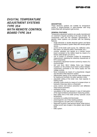
  • 1. DIGITAL TEMPERATURE ADJUSTMENT SYSTEMS DESCRIPTION TYPE 354 These electronic systems are suitable for temperature control in closed-chamber or open-chamber wall hung WITH REMOTE CONTROL boilers fitted with atmospheric gas burners. BOARD TYPE 364 GENERAL FEATURES Temperature adjustment systems are usually manufactured on customer's request according to the type of boiler, the components used and the operation specifications. In general, these systems are provided with the following features: − single electrode or double electrode ignition and flame monitoring (ionisation) system fitted with remote ignition device; − control of the boiler parts (pump, fan, deflection valve, flow switch, air pressure switch, thermostats, etc.); − controls, adjusters and signals on a remote control board connected to the mother board by means of a bipolar cable (length up to 20 m); − use of contact or immersion probes for temperature measurement, exploiting the resistivity characteristic of NTC components; − temperature adjustment function control by means of a microcontroller; − 4kV and 8mm SELV (Safety Extra Low Voltage) insulation on the printed circuit board surface between components connected to the mains supply and low voltage controls; − flame modulation by means of a proportional, integral and derivative (PID) electronic system; − differentiated setting of the required water temperature for heating and domestic hot water operation mode; − adjustable setting of the boiler max. heat capacity in heating mode; − domestic mode priority by means of a (power-driven or hydraulic) three-way valve or a flowmeter; − pump overrun and lockout prevention and deflection valve lockout prevention; − antifreeze function; − cancellation of the heat demand in case of interruption of the signal emitted by temperature measuring probes; − fixed safety limit of the boiler primary hydraulic circuit temperature; − connection to a safety limit thermostat; − prearranged for use in floor heating systems; − prearranged for use with LPG or natural gas; − diagnostic functions: heat demand signal, boiler lockout, probes cut-off, lack of water in the system, lack of stack draft; − EMC system. 4087_r01 1/6
  • 2. TECHNICAL DATA − The appliance in which this temperature adjustment Supply voltage: 230V-50/60Hz system is mounted must provide adequate protection Operating temperature range: -20°C +60°C against the risk of electric shock (at least IP 20). Humidity: 95% max. at 40°C − Avoid placing control signal cables close to power Protection degree: IP 00 cables. Dimensions: 140x100x44mm INTEGRATED TEMPERATURE ADJUSTMENT SYSTEM Integrated temperature adjustment systems are usually CONSTRUCTION manufactured on customer's request as far as operation The system consists of three units (electronic boards): and control of the boiler parts are concerned. For a more a) Mother Board (SM), which houses the boiler control detailed description, we will refer to a particular type, the and the connections to the remaining components; main features of which are shown in Fig. 2. The integrated b) Ignition and Control Module (ACF): this board, temperature adjustment system we are going to consider carrying out the burner safety functions, can control a consists of the following components: single electrode or double electrode system, and is mounted directly on the mother board by soldering, - Ignition and Control Module (ACF) thus reducing the number of wires on the power Timings: switchboard; the surface of this board is protected with epoxy resin to prevent possible damages resulting - waiting or prepurge time (TW): 1,5 … 40 s from incautious handling or external agents such as - safety time (TS): 3 … 60 s dust or humidity; - drop-out time on flame failure: <1s c) Control Board (SC), on which adjustment controls (push-buttons) and diagnostic signals (on a display) The above times correspond to guaranteed values. are mounted. Actual values may differ from declared ones, as waiting The above units are fitted to a Remote Ignition Device or prepurge time may be longer and safety time shorter. (AR) controlled by ACF, reducing electromagnetic interference and enabling the system to fully comply with - Power consumption, start-up: electromagnetic compatibility standards without using any - open chamber 18VA filters. (for technical characteristics, see our data sheets - closed chamber 20VA “REMOTE IGNITION TRANSFORMERS TYPE TR2”). The use of non-reversible connectors with a different - Power consumption, running: number of poles makes connection easy and reliable. A varistor protects the components from possible voltage - open chamber 15VA transients in the mains supply. - closed chamber 17VA An inbuilt fuse protects the internal relays in case of short circuit on the control outputs. - Max. contact rating: (contacts mounted on SM) - VG1 gas valve: 0.5A cos ϕ ≥ 0.4 ACCESSORIES - Fan: 1A cos ϕ ≥ 0.4 The system can be suppied with: - Max. cable length of - connectors and terminals for wiring (see Fig.1); external components: 1m - contact temperature probes (type ST03, ST04 and ST07); - immersion temperature probes (type ST06 and ST09). - Max. length of the cable connecting control board For the technical characteristics of the probes, see relevant and mother board: 20 m data sheets. As for the connectors, pay attention not to fit terminals and - Internal fuse: 3.15 A quick acting female connectors of different brands. Flame monitoring: The flame detection device makes use of the rectification property of the flame; this device is not FEMALE CONNECTORS TERMINALS provided with any protection impedance, therefore the STOCKO: MKF 2800 STOCKO: RFB 7851 detection electrode is not safe against electric shock. STELVIO:BS95/... STELVIO: CT84 Fig.1 - Min. ionisation current: 0.5µA - Recommended ionisation current: 3÷5 times the min. ionisation current DIRECTIONS FOR INSTALLATION - Max. cable length: 1m − Respect the applicable national and European - Min. insulation resistance of detection standards (e.g. EN60335-1/prEN50165) regarding electrode and cable to earth: ≥ 50 MΩ electrical safety. - Electrode max. stray capacitance: ≤ 1 nF − Connect live and neutral correctly; the non-observance - Max. short circuit current: < 200µA AC of live-neutral polarity may cause a dangerous situation. − Before starting the system check the cables carefully; a wrong wiring can damage the devices and compromise the safety of the installation. − Connect and disconnect the control system only after switching off the power supply. − The system can be mounted in any position. − Avoid exposing the system to dripping water. 2/6 4087_r01
  • 3. ♦ MOTHER BOARD (SM) - Temperature measuring probes - External probe The system operates with one or two temperature The control board (SC) is prearranged for the measuring probes, depending on the type of boiler. connection to an NTC sensor (similar to the one For boilers for heating only, the system only uses used in temperature probes), which measures the the heating probe (SR), which is usually placed on temperature outside the building in which the the output pipe of the boiler heat exchanger. For installation is placed. The available adjustments for boilers for domestic hot water production, the the user in heating mode are the required room system also uses the domestic probe (SS), which is temperature and the heat dispersion coefficient of usually placed on the output pipe of the domestic the room walls. The temperature appearing on the circuit. In case of short circuit or cut-off of one of the display is the temperature measured by the primary probes, depending on the type of boiler the circuit probe, and in running state it will have the temperature adjustment system can either operate same value as the set-point resulting from the with the remaining probe, signalling a failure, or processing of the two preset parameters and the cancel any heat demand, preventing the boiler from outside temperature. Upon variation in the latter operating. one, the primary circuit set-point changes The probe fitted to the heating circuit (SR) also automatically to reach the preset room temperature. operates as limit thermostat, thus stopping any heat demand if the water temperature exceeds the preset limit temperature. Functions of the mother board - Safety thermostat - Setting functions during installation In general, the boiler is perfectly safe against During the boiler installation, some system functions possible overtemperature in the primary circuit: to are usually set (see below), which are mainly related this purpose, a safety thermostat is used, which is to the features of the system itself. Please note that connected to the mother board (SM) in series to the these settings are only possible through the jumpers gas valve. The thermostat stops the gas flow and J16-19, therefore they cannot be carried out by the consequently extinguishes the flame; then a starting user once the boiler has been closed. attempt occurs followed by non-volatile lockout. Before trying to start a new ignition cycle, reset the - Function of jumpers (Fig. 2) system manually. The mother board is provided with a number of jumpers to fit the temperature adjustment system to the final installation: J7 must be inserted for LPG systems; - Air pressure switch (for closed-chamber boilers J16 in position 0: the user's normal functions only) (domestic hot water mode, heating mode, It checks the circulation of combustion products in summer/winter selection) are available on the the combustion chamber and allows boiler ignition only if the fan is operating and the draft is regular; it control board (SC); if J16 is placed in position 1, the also ensures the boiler safety shutdown if one of parameters which are useful during setting can be these conditions fails during operation. Upon adjusted; request, in open-chamber boilers the air pressure J17 in position 0: it requires a delay of at least 2,5 switch can be replaced by a combustion products min. between a turnoff and subsequent re-ignition in discharge safety device using the same connector. heating mode; if J17 is placed in position 1, re- ignition occurs as soon as the temperature drops of 5°C below the preset value; J18 in position 0: it enables heat adjustment in - Water pressure switch / Pressure transducer traditional systems (variable from 30 to 80°C); It ensures that the primary circuit pressure is within placed in position 1, it enables heat adjustment in the required operation range. In case the pressure floor heating systems (variable from 15 to 40°C); is too low, the temperature adjustment system stops J19 in position 0: it adjusts domestic hot water any heat demand and the type of failure appears on temperature from 30 to 60°C; placed in position 1, it the control panel. In case a pressure transducer is selects hot water tank boilers or boilers for heating used, the pressure level can be displayed on the only. control panel through 5 LEDs. - Water flow switch / Flowmeter The SM is provided with an input for the connection of either a water flow switch or a flowmeter signalling domestic water drawing. The deflection three-way-valve (if available) can be automatic (hydraulic) or electrically controlled by the system. - Room thermostat The room thermostat is connected on the remote control board (SC) by two wires; it is designed to operate with a contact isolated from the mains supply. 4087_r01 3/6
  • 4. ♦ REMOTE CONTROL BOARD (SC) ( type 364 ) OPERATING CYCLE TA The following operating cycle refers to the temperature adjustment system described above. Starting cycle The starting cycle begins on heat demand by the room SIGN 0V thermostat (heating mode) or the water flow switch / flowmeter (domestic hot water mode). The water pump is energized, and if the water temperature is lower than the Led fiamma preset value, a burner starting demand will occur. L SW8 EP In case of a closed-chamber boiler, the control unit starts DR S E the fan only if the air pressure switch is in "no-air-flow" S position; when it switches into "air-flow" position, the F S SW7 AI prepurge time TW begins, at the end of which the gas valve S O is supplied, the ignition device is started and the safety time CN I E TS begins. In this stage, the burner heat capacity is kept at A SW6 a low value (slow ignition). If a flame signal is detected at the end of TS, the temperature adjustment process will begin, and the burner flame will be modulated in order to reach the same water temperature as the preset value. If no flame signal is detected within the safety time, on the SW3 SW4 SW1 SW2 SW5 elapsing of TS the gas valve will close and lockout will occur. The boiler lockout is signalled on the control panel; The control board is fitted with the following: eight to reset the system press the corresponding push-button. push-buttons (enabling the user to carry out any If hot water demand still occurs, the boiler will start a new adjustment and setting during installation), two ignition cycle; if the conditions leading to lockout still occur, displays (showing temperature, settings and failure the boiler will go back to lockout. The boiler keeps on signals), a LED signalling flame on, and five LEDs running until either heat demand stops, or one of the safety for system pressure indication (in case a pressure devices switches on, or the flame extinguishes. transducer is available); pressure ranges can be customized through the software. Domestic hot water mode - Display Ignition demand in domestic mode has priority over heating The two-digit display usually shows the current mode. The boiler burner ignition occurs when hot water is water temperature in heating or domestic mode; drawn; the boiler will try and supply the user with domestic however, when pressing one of the push-buttons for hot water at preset temperature (variable from 30 to 60°C). water temperature adjustment, the display shows If the required capacity is lower than the min. modulation first the last preset temperature value and then the capacity, the boiler will perform short ignition and turnoff current temperature setting. cycles. If the required capacity is higher than the boiler If the adjustment functions required during max. capacity, the water temperature will be proportional to installation are recalled, the display shows a the quantity of drawn water, but lower than preset percentage value indicating the adjustment level (0- temperature. 99%). - Functions of remote control board push-buttons Heating mode The standard function of push-buttons with J16 in If the boiler is in winter position, and on room thermostat position 0 is the following: switching off the outgoing water temperature is lower than SW3 : heating set-point decrease the preset value, boiler ignition will occur and flame SW4 : heating set-point increase modulation will begin until the boiler reaches the running SW1 : domestic set-point decrease condition. If the outgoing water temperature is 5°C higher SW2 : domestic set-point increase than the value previously adjusted by the user (variable SW5 : Summer / Winter selection from 30 to 80°C), the boiler will switch off; re -ignition occurs SW6 : available for particular functions SW7 : boiler reset as soon as the water temperature drops of 5°C below the SW8 : boiler ON/OFF preset value, provided that at least 150 sec have elapsed from the boiler switching off. The boiler max. capacity in If J16 is in position 1 (for the installer), the function heating mode is set during installation through the push- of push-buttons is the following: buttons on the control panel. SW3 : heating capacity decrease SW4 : heating capacity increase SW1 : soft-start decrease SW2 : soft-start increase SW5,SW6,SW7 : not working SW8 : boiler ON/OFF The "chimney-sweep" function can be switched on by pressing the two push-buttons SW8+SW5 simultaneously. The function can be switched off by pressing the push-button SW3. REMARK: the functions of push-buttons can be customized upon request. 4/6 4087_r01
  • 5. SYSTEM SELF-CHECK AND SAFEGUARD FUNCTIONS - Circulator lockout prevention: The system is provided with some diagnostic functions If the boiler has not carried out any ignition cycle within signalling the boiler operation status and the type of failures a given period of time (usually 24 hours), the circulator which may occur. will switch on for a few seconds to avoid lockout due to protracted non-operation. Any failures are signalled on the remote control board according to the following table: - Antifreeze function: When the system probe measures a temperature lower Display Description than 6°C, the burner starts at lowest power and the E 00 Internal system error (EEPROM) pump switches on. This status persists until a E 01 Installation pressure < 0.5 bar temperature of 20°C is reached. E 02 Lockout due to ignition failure - "Chimney-sweep" function: E 03 Faulty outgoing water probe (SM) This function is meant to switch off the boiler normal E 04 Faulty domestic water probe (SS) adjustment control, making the boiler work at max. E 06 Lack of air or combustion products available heat capacity. This function is useful during discharge failure installation and when taking any combustion products checking measures, as required by the standards in Other functions are related to the installation safeguard: force. This function can be switched off manually or on any domestic hot water demand. - Circulator overrun: Every time the boiler switches off (in heating mode), the circulator keeps on running for a short time (5 seconds), in order to avoid water overheating in the primary heat exchanger. DIMENSIONS BOARD TYPE 354 16 mm 3 mm 3,4 mm 39 mm 94 mm 100 mm 26.5 mm 134 mm 3 mm 140 mm 40 mm CASING FOR CONTROL BOARD TYPE 364 100 mm 36.2 mm 70 mm 4087_r01 5/6
  • 6. WIRING DIAGRAM P H 20 0V 5V IN FL O W SW IT C H 7 0V S IG N SIN G L E EL EC T R O D E D O U BL E E LE C T R O D E MB AU X Fig.2 KEY BOARD: L power supply line SR heating circuit probe TR ignition transformer N neutral SS domestic circuit probe AUX auxiliary output P pump VG gas valve U2 safety module I ionisation TS safety thermostat TL limit thermostat MB fan MOD modulator (24 V) PR air pressure switch PH2O water pressure switch ( transducer ) 0 - SIGN signals to be connected to the remote control board FUNCTION OF JUMPERS J7 LPG / natural gas J16 installer's setting J19 domestic temperature range / J17 re-ignition interval J18 floor heating system boiler type selection BRAHMA S.p.A. Via del Pontiere, 31 37045 Legnago (VR) - ITALY Tel. +39 0442 635211 - Fax +39 0442 25683 03/12/12 Subject to amendments without notice http://www.brahma.it E-mail: brahma@brahma.it 6/6 4087_r01