SlideShare una empresa de Scribd logo
1 de 13
Descargar para leer sin conexión
MULTIPLEXING
The purpose of multiplexing is to share the bandwidth of a single
transmission channel among several users. Two multiplexing methods
are commonly used in fiber optics:
1. Time-division multiplexing (TDM)
2. Wavelength-division multiplexing (WDM)
A. Time-Division Multiplexing (TDM)
In time-division multiplexing, time on the information channel, or fiber, is shared
among the many data sources. The multiplexer MUX can be described as a
type of “rotary switch,” which rotates at a very high speed, individually
connecting each input to the communication channel for a fixed period of time.
The process is reversed on the output with a device known as a demultiplexer,
or DEMUX. After each channel has been sequentially connected, the process
repeats itself. One complete cycle is known as a frame. To ensure that each
channel on the input is connected to its corresponding channel on the output,
start and stop frames are added to synchronize the input with the output. TDM
systems may send information using any of the digital modulation schemes
described (analog multiplexing systems also exist).
The amount of data that can be transmitted using TDM is given by the
MUX output rate and is defined by :
MUX output rate = N × Maximum input rate
where N is the number of input channels and the maximum input rate is the
highest data rate in bits/second of the various inputs. The bandwidth of the
communication channel must be at least equal to the MUX output rate. Another
parameter commonly used in describing the information capacity of a TDM
system is the channel-switching rate. This is equal to the number of inputs
visited per second by the MUX and is defined as;
Channel switching rate = Input data rate × Number of channels
Exercise 3.1 :
A digital MUX operates with 8 sources. The rate of data in each source is 1000
bytes/s. Assume that 8-bits-per-byte data is transmitted byte by byte.
1. What is the data rate of the MUX output?
2. What is the channel switching rate?
B. Wavelength-Division Multiplexing (WDM)
In wavelength-division multiplexing, each data channel is transmitted using a
slightly different wavelength (different color). With use of a different wavelength
for each channel, many channels can be transmitted through the same fiber
without interference. This method is used to increase the capacity of existing
fiber optic systems many times. Each WDM data channel may consist of a
single data source or may be a combination of a single data source and a TDM
(time-division multiplexing) and/or FDM (frequency-division multiplexing) signal.
Dense wavelength-division multiplexing (DWDM) refers to the transmission of
multiple closely spaced wavelengths through the same fiber. For any given
wavelength λ and corresponding frequency f, the International
Telecommunications Union (ITU) defines standard frequency spacing Δf as 100
GHz, which translates into a Δλ of 0.8-nm wavelength spacing.
Wavelength-division multiplexing
This follows from the relationship
The couplers used for wavelength-division multiplexing (WDM) are
designed specifically to make the coupling between ports a function of
wavelength. The purpose of these couplers is to separate (or combine)
signals transmitted at different wavelengths. Essentially, the
transmitting coupler is a mixer and the receiving coupler is a wavelength
filter. Wavelength-division multiplexers use several methods to separate
different wavelengths depending on the spacing between the
wavelengths. Separation of 1310 nm and 1550 nm is a simple operation
and can be achieved with WDMs using bulk optical diffraction gratings.
Wavelengths in the 1550-nm range that are spaced at greater than 1 to
2 nm can be resolved using WDMs that incorporate interference filters.
An example of an 8-channel WDM using interference filters is given in
Figure 8-38. Fiber Bragg gratings are typically used to separate very
closely spaced wavelengths in a DWDM system (< 0.8 nm).
channel WDM
C. Dense Wavelength-Division Multiplexing (DWDM)
Erbium-Doped Fiber Amplifiers (EDFA )
DWDM systems operate in the 1550-nm window because of the low
attenuation characteristics of glass at 1550 nm and the fact that erbium-
doped fiber amplifiers (EDFA) operate in the 1530-nm–1570-nm range.
Commercially available systems today can multiplex up to 128 individual
wavelengths at 2.5 Gb/s or 32 individual wavelengths at 10 Gb/s
Erbium-doped fiber amplifiers (EDFA)—The EDFA is an optical amplifier
used to boost the signal level in the 1530-nm to 1570-nm region of the
spectrum. When it is pumped by an external laser source of either 980
nm or 1480 nm, signal gain can be as high as 30 dB (1000 times).
Because EDFAs allow signals to be regenerated without having to be
converted back to electrical signals, systems are faster and more
reliable. When used in conjunction with wavelength-division
multiplexing, fiber optic systems can transmit enormous amounts of
information over long distances with very high reliability
Fiber Bragg gratings—Fiber Bragg gratings are devices that are used for
separating wavelengths through diffraction, similar to a diffraction
grating (see Figure 8-40). They are of critical importance in DWDM
systems in which multiple closely spaced wavelengths require
separation. Light entering the fiber Bragg grating is diffracted by the
induced period variations in the index of refraction. By spacing the
periodic variations at multiples of the half-wavelength of the desired
signal, each variation reflects light with a 360° phase shift causing a
constructive interference of a very specific wavelength while allowing
others to pass. Fiber Bragg gratings are available with bandwidths
ranging from 0.05 nm to >20 nm. Fiber Bragg grating are typically used
in conjunction with circulators, which are used to drop single or multiple
narrow- band WDM channels and to pass other “express” channels (see
Figure 8-41). Fiber Bragg gratings have emerged as a major factor, along
with EDFAs, in increasing the capacity of next- generation high-
bandwidth fiber optic systems
DWDM and EDFA technology is used to transmit a number of different
channels of high-bandwidth information over a single fiber. As shown, n-
individual wavelengths of light operating in accordance with the ITU grid
are multiplexed together using a multichannel coupler/splitter or
wavelength-division multiplexer. An optical isolator is used with each
optical source to minimize troublesome back reflections.
A tap coupler then removes 3% of the transmitted signal for wavelength
and power monitoring. Upon traveling through a substantial length of
fiber (50-100 Km), an EDFA is used to boost the signal strength. After a
couple of stages of amplifications, an add/drop channel consisting of a
fiber Bragg grating and circulator is introduced to extract and then
reinject the signal operating at the ë3 wavelength. After another stage
of amplification via EDFA, a broadband WDM is used to combine a 1310-
nm signal with the 1550-nm window signals. At the receiver end,
another broadband WDM extracts the 1310-nm signal, leaving the 1550-
nm window signals. The 1550-nm window signals are finally separated
using a DWDM that employs an array of
fiber Bragg gratings, each tuned to the specific transmission wavelength.
This system represents the current state of the art in high-bandwidth
fiber optic data transmission.
Exercise 3.2:
1. The C and L spectral bands cover a wavelength range from 1.53 to
1.61 µm. How many channels can be transmitted through WDM
when the channel spacing is 25 GHz? What is the effective bit rate–
distance product when a WDM signal covering the two bands using
10-Gb/s channels is transmitted over 2000 km
2. A 128 × 128 broadcast star is made by using 2 × 2 directional
couplers, each having an insertion loss of 0.2 dB. Each channel
transmits 1 mW of average power and requires 1 µW of average
received power for operation at 1 Gb/s.
What is the maximum transmission distance for each channel?
Assume a cable loss of 0.25 dB/km and a loss of 3 dB from
connectors and splices

Más contenido relacionado

Similar a MULTIPLEXING.pdf

Wavelenth division multiplexing
Wavelenth division multiplexingWavelenth division multiplexing
Wavelenth division multiplexingArjun Achu
 
What does WDM (Wavelength Division Multiplexing )stand for?
What does WDM (Wavelength Division Multiplexing )stand for?What does WDM (Wavelength Division Multiplexing )stand for?
What does WDM (Wavelength Division Multiplexing )stand for?HYC Co., Ltd
 
Multiplexing,LAN Cabling,Routers,Core and Distribution Networks
Multiplexing,LAN Cabling,Routers,Core and Distribution NetworksMultiplexing,LAN Cabling,Routers,Core and Distribution Networks
Multiplexing,LAN Cabling,Routers,Core and Distribution NetworksPanimalar Engineering College
 
24 Multiplexing_Techniques.pdf
24 Multiplexing_Techniques.pdf24 Multiplexing_Techniques.pdf
24 Multiplexing_Techniques.pdfMohamedshabana38
 
Integrated DWDM and MIMO-OFDM System for 4G High Capacity Mobile Communicatio...
Integrated DWDM and MIMO-OFDM System for 4G High Capacity Mobile Communicatio...Integrated DWDM and MIMO-OFDM System for 4G High Capacity Mobile Communicatio...
Integrated DWDM and MIMO-OFDM System for 4G High Capacity Mobile Communicatio...CSCJournals
 
Dense wavelength division multiplexing....
Dense wavelength division multiplexing....Dense wavelength division multiplexing....
Dense wavelength division multiplexing....Arif Ahmed
 
Multiplexing and spreading
Multiplexing and spreadingMultiplexing and spreading
Multiplexing and spreadingShankar Gangaju
 
Mitigation of non-linear four-wave mixing phenomenon in a fully optical commu...
Mitigation of non-linear four-wave mixing phenomenon in a fully optical commu...Mitigation of non-linear four-wave mixing phenomenon in a fully optical commu...
Mitigation of non-linear four-wave mixing phenomenon in a fully optical commu...TELKOMNIKA JOURNAL
 
WDM &amp; Optical Amplifiers
WDM &amp; Optical AmplifiersWDM &amp; Optical Amplifiers
WDM &amp; Optical AmplifiersEng_Ahmad
 
Successful interference cancellation with Blind Equalization method for MC-CD...
Successful interference cancellation with Blind Equalization method for MC-CD...Successful interference cancellation with Blind Equalization method for MC-CD...
Successful interference cancellation with Blind Equalization method for MC-CD...IJTET Journal
 
RZ based dispersion compensation technique in dwdm system for broadband spectrum
RZ based dispersion compensation technique in dwdm system for broadband spectrumRZ based dispersion compensation technique in dwdm system for broadband spectrum
RZ based dispersion compensation technique in dwdm system for broadband spectrumRamesh Patriotic
 

Similar a MULTIPLEXING.pdf (20)

DWDM_Trainning.pptx
DWDM_Trainning.pptxDWDM_Trainning.pptx
DWDM_Trainning.pptx
 
Wavelenth division multiplexing
Wavelenth division multiplexingWavelenth division multiplexing
Wavelenth division multiplexing
 
What does WDM (Wavelength Division Multiplexing )stand for?
What does WDM (Wavelength Division Multiplexing )stand for?What does WDM (Wavelength Division Multiplexing )stand for?
What does WDM (Wavelength Division Multiplexing )stand for?
 
Wavelength division multiplexing
Wavelength division multiplexingWavelength division multiplexing
Wavelength division multiplexing
 
Multiplexing,LAN Cabling,Routers,Core and Distribution Networks
Multiplexing,LAN Cabling,Routers,Core and Distribution NetworksMultiplexing,LAN Cabling,Routers,Core and Distribution Networks
Multiplexing,LAN Cabling,Routers,Core and Distribution Networks
 
24 Multiplexing_Techniques.pdf
24 Multiplexing_Techniques.pdf24 Multiplexing_Techniques.pdf
24 Multiplexing_Techniques.pdf
 
MULTIPLEX.pptx
MULTIPLEX.pptxMULTIPLEX.pptx
MULTIPLEX.pptx
 
Integrated DWDM and MIMO-OFDM System for 4G High Capacity Mobile Communicatio...
Integrated DWDM and MIMO-OFDM System for 4G High Capacity Mobile Communicatio...Integrated DWDM and MIMO-OFDM System for 4G High Capacity Mobile Communicatio...
Integrated DWDM and MIMO-OFDM System for 4G High Capacity Mobile Communicatio...
 
MULTIPLEXERS
MULTIPLEXERSMULTIPLEXERS
MULTIPLEXERS
 
Dense wavelength division multiplexing....
Dense wavelength division multiplexing....Dense wavelength division multiplexing....
Dense wavelength division multiplexing....
 
Multiplexing and spreading
Multiplexing and spreadingMultiplexing and spreading
Multiplexing and spreading
 
Introduction To WDM and TDM
Introduction To WDM and TDMIntroduction To WDM and TDM
Introduction To WDM and TDM
 
Introduction to WDM and TDM
 Introduction to WDM and TDM Introduction to WDM and TDM
Introduction to WDM and TDM
 
Dwdm
DwdmDwdm
Dwdm
 
Mitigation of non-linear four-wave mixing phenomenon in a fully optical commu...
Mitigation of non-linear four-wave mixing phenomenon in a fully optical commu...Mitigation of non-linear four-wave mixing phenomenon in a fully optical commu...
Mitigation of non-linear four-wave mixing phenomenon in a fully optical commu...
 
WDM &amp; Optical Amplifiers
WDM &amp; Optical AmplifiersWDM &amp; Optical Amplifiers
WDM &amp; Optical Amplifiers
 
Dwdm
DwdmDwdm
Dwdm
 
Successful interference cancellation with Blind Equalization method for MC-CD...
Successful interference cancellation with Blind Equalization method for MC-CD...Successful interference cancellation with Blind Equalization method for MC-CD...
Successful interference cancellation with Blind Equalization method for MC-CD...
 
Multiplexing : FDM
Multiplexing : FDMMultiplexing : FDM
Multiplexing : FDM
 
RZ based dispersion compensation technique in dwdm system for broadband spectrum
RZ based dispersion compensation technique in dwdm system for broadband spectrumRZ based dispersion compensation technique in dwdm system for broadband spectrum
RZ based dispersion compensation technique in dwdm system for broadband spectrum
 

Último

Call Girls Wakad Call Me 7737669865 Budget Friendly No Advance Booking
Call Girls Wakad Call Me 7737669865 Budget Friendly No Advance BookingCall Girls Wakad Call Me 7737669865 Budget Friendly No Advance Booking
Call Girls Wakad Call Me 7737669865 Budget Friendly No Advance Bookingroncy bisnoi
 
Hazard Identification (HAZID) vs. Hazard and Operability (HAZOP): A Comparati...
Hazard Identification (HAZID) vs. Hazard and Operability (HAZOP): A Comparati...Hazard Identification (HAZID) vs. Hazard and Operability (HAZOP): A Comparati...
Hazard Identification (HAZID) vs. Hazard and Operability (HAZOP): A Comparati...soginsider
 
XXXXXXXXXXXXXXXXXXXXXXXXXXXXXXXXXXXXXXXXXXXXXXXXXXXX
XXXXXXXXXXXXXXXXXXXXXXXXXXXXXXXXXXXXXXXXXXXXXXXXXXXXXXXXXXXXXXXXXXXXXXXXXXXXXXXXXXXXXXXXXXXXXXXXXXXXXXXX
XXXXXXXXXXXXXXXXXXXXXXXXXXXXXXXXXXXXXXXXXXXXXXXXXXXXssuser89054b
 
Double Revolving field theory-how the rotor develops torque
Double Revolving field theory-how the rotor develops torqueDouble Revolving field theory-how the rotor develops torque
Double Revolving field theory-how the rotor develops torqueBhangaleSonal
 
Unit 2- Effective stress & Permeability.pdf
Unit 2- Effective stress & Permeability.pdfUnit 2- Effective stress & Permeability.pdf
Unit 2- Effective stress & Permeability.pdfRagavanV2
 
Navigating Complexity: The Role of Trusted Partners and VIAS3D in Dassault Sy...
Navigating Complexity: The Role of Trusted Partners and VIAS3D in Dassault Sy...Navigating Complexity: The Role of Trusted Partners and VIAS3D in Dassault Sy...
Navigating Complexity: The Role of Trusted Partners and VIAS3D in Dassault Sy...Arindam Chakraborty, Ph.D., P.E. (CA, TX)
 
Top Rated Call Girls In chittoor 📱 {7001035870} VIP Escorts chittoor
Top Rated Call Girls In chittoor 📱 {7001035870} VIP Escorts chittoorTop Rated Call Girls In chittoor 📱 {7001035870} VIP Escorts chittoor
Top Rated Call Girls In chittoor 📱 {7001035870} VIP Escorts chittoordharasingh5698
 
data_management_and _data_science_cheat_sheet.pdf
data_management_and _data_science_cheat_sheet.pdfdata_management_and _data_science_cheat_sheet.pdf
data_management_and _data_science_cheat_sheet.pdfJiananWang21
 
DC MACHINE-Motoring and generation, Armature circuit equation
DC MACHINE-Motoring and generation, Armature circuit equationDC MACHINE-Motoring and generation, Armature circuit equation
DC MACHINE-Motoring and generation, Armature circuit equationBhangaleSonal
 
chapter 5.pptx: drainage and irrigation engineering
chapter 5.pptx: drainage and irrigation engineeringchapter 5.pptx: drainage and irrigation engineering
chapter 5.pptx: drainage and irrigation engineeringmulugeta48
 
ONLINE FOOD ORDER SYSTEM PROJECT REPORT.pdf
ONLINE FOOD ORDER SYSTEM PROJECT REPORT.pdfONLINE FOOD ORDER SYSTEM PROJECT REPORT.pdf
ONLINE FOOD ORDER SYSTEM PROJECT REPORT.pdfKamal Acharya
 
Unleashing the Power of the SORA AI lastest leap
Unleashing the Power of the SORA AI lastest leapUnleashing the Power of the SORA AI lastest leap
Unleashing the Power of the SORA AI lastest leapRishantSharmaFr
 
Hostel management system project report..pdf
Hostel management system project report..pdfHostel management system project report..pdf
Hostel management system project report..pdfKamal Acharya
 
2016EF22_0 solar project report rooftop projects
2016EF22_0 solar project report rooftop projects2016EF22_0 solar project report rooftop projects
2016EF22_0 solar project report rooftop projectssmsksolar
 

Último (20)

Call Girls Wakad Call Me 7737669865 Budget Friendly No Advance Booking
Call Girls Wakad Call Me 7737669865 Budget Friendly No Advance BookingCall Girls Wakad Call Me 7737669865 Budget Friendly No Advance Booking
Call Girls Wakad Call Me 7737669865 Budget Friendly No Advance Booking
 
Hazard Identification (HAZID) vs. Hazard and Operability (HAZOP): A Comparati...
Hazard Identification (HAZID) vs. Hazard and Operability (HAZOP): A Comparati...Hazard Identification (HAZID) vs. Hazard and Operability (HAZOP): A Comparati...
Hazard Identification (HAZID) vs. Hazard and Operability (HAZOP): A Comparati...
 
Call Now ≽ 9953056974 ≼🔝 Call Girls In New Ashok Nagar ≼🔝 Delhi door step de...
Call Now ≽ 9953056974 ≼🔝 Call Girls In New Ashok Nagar  ≼🔝 Delhi door step de...Call Now ≽ 9953056974 ≼🔝 Call Girls In New Ashok Nagar  ≼🔝 Delhi door step de...
Call Now ≽ 9953056974 ≼🔝 Call Girls In New Ashok Nagar ≼🔝 Delhi door step de...
 
Water Industry Process Automation & Control Monthly - April 2024
Water Industry Process Automation & Control Monthly - April 2024Water Industry Process Automation & Control Monthly - April 2024
Water Industry Process Automation & Control Monthly - April 2024
 
XXXXXXXXXXXXXXXXXXXXXXXXXXXXXXXXXXXXXXXXXXXXXXXXXXXX
XXXXXXXXXXXXXXXXXXXXXXXXXXXXXXXXXXXXXXXXXXXXXXXXXXXXXXXXXXXXXXXXXXXXXXXXXXXXXXXXXXXXXXXXXXXXXXXXXXXXXXXX
XXXXXXXXXXXXXXXXXXXXXXXXXXXXXXXXXXXXXXXXXXXXXXXXXXXX
 
Double Revolving field theory-how the rotor develops torque
Double Revolving field theory-how the rotor develops torqueDouble Revolving field theory-how the rotor develops torque
Double Revolving field theory-how the rotor develops torque
 
FEA Based Level 3 Assessment of Deformed Tanks with Fluid Induced Loads
FEA Based Level 3 Assessment of Deformed Tanks with Fluid Induced LoadsFEA Based Level 3 Assessment of Deformed Tanks with Fluid Induced Loads
FEA Based Level 3 Assessment of Deformed Tanks with Fluid Induced Loads
 
Integrated Test Rig For HTFE-25 - Neometrix
Integrated Test Rig For HTFE-25 - NeometrixIntegrated Test Rig For HTFE-25 - Neometrix
Integrated Test Rig For HTFE-25 - Neometrix
 
Unit 2- Effective stress & Permeability.pdf
Unit 2- Effective stress & Permeability.pdfUnit 2- Effective stress & Permeability.pdf
Unit 2- Effective stress & Permeability.pdf
 
Navigating Complexity: The Role of Trusted Partners and VIAS3D in Dassault Sy...
Navigating Complexity: The Role of Trusted Partners and VIAS3D in Dassault Sy...Navigating Complexity: The Role of Trusted Partners and VIAS3D in Dassault Sy...
Navigating Complexity: The Role of Trusted Partners and VIAS3D in Dassault Sy...
 
Cara Menggugurkan Sperma Yang Masuk Rahim Biyar Tidak Hamil
Cara Menggugurkan Sperma Yang Masuk Rahim Biyar Tidak HamilCara Menggugurkan Sperma Yang Masuk Rahim Biyar Tidak Hamil
Cara Menggugurkan Sperma Yang Masuk Rahim Biyar Tidak Hamil
 
Top Rated Call Girls In chittoor 📱 {7001035870} VIP Escorts chittoor
Top Rated Call Girls In chittoor 📱 {7001035870} VIP Escorts chittoorTop Rated Call Girls In chittoor 📱 {7001035870} VIP Escorts chittoor
Top Rated Call Girls In chittoor 📱 {7001035870} VIP Escorts chittoor
 
(INDIRA) Call Girl Bhosari Call Now 8617697112 Bhosari Escorts 24x7
(INDIRA) Call Girl Bhosari Call Now 8617697112 Bhosari Escorts 24x7(INDIRA) Call Girl Bhosari Call Now 8617697112 Bhosari Escorts 24x7
(INDIRA) Call Girl Bhosari Call Now 8617697112 Bhosari Escorts 24x7
 
data_management_and _data_science_cheat_sheet.pdf
data_management_and _data_science_cheat_sheet.pdfdata_management_and _data_science_cheat_sheet.pdf
data_management_and _data_science_cheat_sheet.pdf
 
DC MACHINE-Motoring and generation, Armature circuit equation
DC MACHINE-Motoring and generation, Armature circuit equationDC MACHINE-Motoring and generation, Armature circuit equation
DC MACHINE-Motoring and generation, Armature circuit equation
 
chapter 5.pptx: drainage and irrigation engineering
chapter 5.pptx: drainage and irrigation engineeringchapter 5.pptx: drainage and irrigation engineering
chapter 5.pptx: drainage and irrigation engineering
 
ONLINE FOOD ORDER SYSTEM PROJECT REPORT.pdf
ONLINE FOOD ORDER SYSTEM PROJECT REPORT.pdfONLINE FOOD ORDER SYSTEM PROJECT REPORT.pdf
ONLINE FOOD ORDER SYSTEM PROJECT REPORT.pdf
 
Unleashing the Power of the SORA AI lastest leap
Unleashing the Power of the SORA AI lastest leapUnleashing the Power of the SORA AI lastest leap
Unleashing the Power of the SORA AI lastest leap
 
Hostel management system project report..pdf
Hostel management system project report..pdfHostel management system project report..pdf
Hostel management system project report..pdf
 
2016EF22_0 solar project report rooftop projects
2016EF22_0 solar project report rooftop projects2016EF22_0 solar project report rooftop projects
2016EF22_0 solar project report rooftop projects
 

MULTIPLEXING.pdf

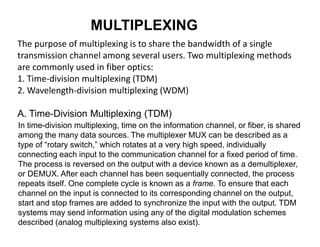
  • 1. MULTIPLEXING The purpose of multiplexing is to share the bandwidth of a single transmission channel among several users. Two multiplexing methods are commonly used in fiber optics: 1. Time-division multiplexing (TDM) 2. Wavelength-division multiplexing (WDM) A. Time-Division Multiplexing (TDM) In time-division multiplexing, time on the information channel, or fiber, is shared among the many data sources. The multiplexer MUX can be described as a type of “rotary switch,” which rotates at a very high speed, individually connecting each input to the communication channel for a fixed period of time. The process is reversed on the output with a device known as a demultiplexer, or DEMUX. After each channel has been sequentially connected, the process repeats itself. One complete cycle is known as a frame. To ensure that each channel on the input is connected to its corresponding channel on the output, start and stop frames are added to synchronize the input with the output. TDM systems may send information using any of the digital modulation schemes described (analog multiplexing systems also exist).
  • 2. The amount of data that can be transmitted using TDM is given by the MUX output rate and is defined by : MUX output rate = N × Maximum input rate
  • 3. where N is the number of input channels and the maximum input rate is the highest data rate in bits/second of the various inputs. The bandwidth of the communication channel must be at least equal to the MUX output rate. Another parameter commonly used in describing the information capacity of a TDM system is the channel-switching rate. This is equal to the number of inputs visited per second by the MUX and is defined as; Channel switching rate = Input data rate × Number of channels Exercise 3.1 : A digital MUX operates with 8 sources. The rate of data in each source is 1000 bytes/s. Assume that 8-bits-per-byte data is transmitted byte by byte. 1. What is the data rate of the MUX output? 2. What is the channel switching rate?
  • 4. B. Wavelength-Division Multiplexing (WDM) In wavelength-division multiplexing, each data channel is transmitted using a slightly different wavelength (different color). With use of a different wavelength for each channel, many channels can be transmitted through the same fiber without interference. This method is used to increase the capacity of existing fiber optic systems many times. Each WDM data channel may consist of a single data source or may be a combination of a single data source and a TDM (time-division multiplexing) and/or FDM (frequency-division multiplexing) signal. Dense wavelength-division multiplexing (DWDM) refers to the transmission of multiple closely spaced wavelengths through the same fiber. For any given wavelength λ and corresponding frequency f, the International Telecommunications Union (ITU) defines standard frequency spacing Δf as 100 GHz, which translates into a Δλ of 0.8-nm wavelength spacing.
  • 6. The couplers used for wavelength-division multiplexing (WDM) are designed specifically to make the coupling between ports a function of wavelength. The purpose of these couplers is to separate (or combine) signals transmitted at different wavelengths. Essentially, the transmitting coupler is a mixer and the receiving coupler is a wavelength filter. Wavelength-division multiplexers use several methods to separate different wavelengths depending on the spacing between the wavelengths. Separation of 1310 nm and 1550 nm is a simple operation and can be achieved with WDMs using bulk optical diffraction gratings. Wavelengths in the 1550-nm range that are spaced at greater than 1 to 2 nm can be resolved using WDMs that incorporate interference filters. An example of an 8-channel WDM using interference filters is given in Figure 8-38. Fiber Bragg gratings are typically used to separate very closely spaced wavelengths in a DWDM system (< 0.8 nm).
  • 7. channel WDM C. Dense Wavelength-Division Multiplexing (DWDM) Erbium-Doped Fiber Amplifiers (EDFA ) DWDM systems operate in the 1550-nm window because of the low attenuation characteristics of glass at 1550 nm and the fact that erbium- doped fiber amplifiers (EDFA) operate in the 1530-nm–1570-nm range. Commercially available systems today can multiplex up to 128 individual wavelengths at 2.5 Gb/s or 32 individual wavelengths at 10 Gb/s
  • 8. Erbium-doped fiber amplifiers (EDFA)—The EDFA is an optical amplifier used to boost the signal level in the 1530-nm to 1570-nm region of the spectrum. When it is pumped by an external laser source of either 980 nm or 1480 nm, signal gain can be as high as 30 dB (1000 times). Because EDFAs allow signals to be regenerated without having to be converted back to electrical signals, systems are faster and more reliable. When used in conjunction with wavelength-division multiplexing, fiber optic systems can transmit enormous amounts of information over long distances with very high reliability
  • 9. Fiber Bragg gratings—Fiber Bragg gratings are devices that are used for separating wavelengths through diffraction, similar to a diffraction grating (see Figure 8-40). They are of critical importance in DWDM systems in which multiple closely spaced wavelengths require separation. Light entering the fiber Bragg grating is diffracted by the induced period variations in the index of refraction. By spacing the periodic variations at multiples of the half-wavelength of the desired signal, each variation reflects light with a 360° phase shift causing a constructive interference of a very specific wavelength while allowing others to pass. Fiber Bragg gratings are available with bandwidths ranging from 0.05 nm to >20 nm. Fiber Bragg grating are typically used in conjunction with circulators, which are used to drop single or multiple narrow- band WDM channels and to pass other “express” channels (see Figure 8-41). Fiber Bragg gratings have emerged as a major factor, along with EDFAs, in increasing the capacity of next- generation high- bandwidth fiber optic systems
  • 10.
  • 11. DWDM and EDFA technology is used to transmit a number of different channels of high-bandwidth information over a single fiber. As shown, n- individual wavelengths of light operating in accordance with the ITU grid are multiplexed together using a multichannel coupler/splitter or wavelength-division multiplexer. An optical isolator is used with each optical source to minimize troublesome back reflections. A tap coupler then removes 3% of the transmitted signal for wavelength and power monitoring. Upon traveling through a substantial length of fiber (50-100 Km), an EDFA is used to boost the signal strength. After a couple of stages of amplifications, an add/drop channel consisting of a fiber Bragg grating and circulator is introduced to extract and then reinject the signal operating at the ë3 wavelength. After another stage of amplification via EDFA, a broadband WDM is used to combine a 1310- nm signal with the 1550-nm window signals. At the receiver end, another broadband WDM extracts the 1310-nm signal, leaving the 1550- nm window signals. The 1550-nm window signals are finally separated using a DWDM that employs an array of
  • 12. fiber Bragg gratings, each tuned to the specific transmission wavelength. This system represents the current state of the art in high-bandwidth fiber optic data transmission.
  • 13. Exercise 3.2: 1. The C and L spectral bands cover a wavelength range from 1.53 to 1.61 µm. How many channels can be transmitted through WDM when the channel spacing is 25 GHz? What is the effective bit rate– distance product when a WDM signal covering the two bands using 10-Gb/s channels is transmitted over 2000 km 2. A 128 × 128 broadcast star is made by using 2 × 2 directional couplers, each having an insertion loss of 0.2 dB. Each channel transmits 1 mW of average power and requires 1 µW of average received power for operation at 1 Gb/s. What is the maximum transmission distance for each channel? Assume a cable loss of 0.25 dB/km and a loss of 3 dB from connectors and splices