Más contenido relacionado
La actualidad más candente (20)
Similar a Lab4 manual (20)
Lab4 manual
- 1. Lab Manual (1)
Lab-4: Permanent Magnet Synchronous Machine –
Brushless DC Motor
1 Objectives and Overview
The goals for this laboratory experiment are:
• To fully characterize a 210W PM Synchronous Machine, which is also a Brushless DC
Motor;
• Starting, synchronizing, and operating of Synchronous Motor from a fixed frequency
source;
• Operating of PM Synchronous Motor with Hall-sensor-driven Inverter - Brushless DC
Motor operation.
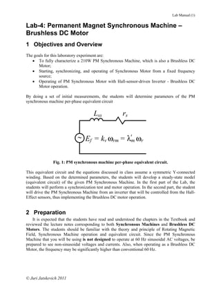
By doing a set of initial measurements, the students will determine parameters of the PM
synchronous machine per-phase equivalent circuit
Lss rs
~ Ef = kv ωrm = λ'm ωr
Fig. 1: PM synchronous machine per-phase equivalent circuit.
This equivalent circuit and the equations discussed in class assume a symmetric Y-connected
winding. Based on the determined parameters, the students will develop a steady-state model
(equivalent circuit) of the given PM Synchronous Machine. In the first part of the Lab, the
students will perform a synchronization test and motor operation. In the second part, the student
will drive the PM Synchronous Machine from an inverter that will be controlled from the Hall-
Effect sensors, thus implementing the Brushless DC motor operation.
2 Preparation
It is expected that the students have read and understood the chapters in the Textbook and
reviewed the lecture notes corresponding to both Synchronous Machines and Brushless DC
Motors. The students should be familiar with the theory and principle of Rotating Magnetic
Field, Synchronous Machine operation and equivalent circuit. Since the PM Synchronous
Machine that you will be using is not designed to operate at 60 Hz sinusoidal AC voltages, be
prepared to see non-sinusoidal voltages and currents. Also, when operating as a Brushless DC
Motor, the frequency may be significantly higher than conventional 60 Hz.
© Juri Jatskevich 2011
- 2. 3 Apparatus
This lab includes the following components:
PM Synchronous Machine – Brushless
DC Motor: This is a PM Synchronous
Machine that can operate from a fixed
frequency source as well as from a
variable frequency inverter. The machine
is equipped with Hall-Effect sensors,
which makes it possible to operate as a
Brushless DC Motor.
This machine should be mounted on the
Motor Bench, wherein the shaft is
coupled to the Dynamometer for taking
the torque and speed measurements.
Prime Mover / Dynamometer Cradle:
A DC machine is mounted in a special
cradle to permit measurements of the
torque and speed on the shaft. The motor
housing is supported along its axis by
ball bearings which enable it to move
when the torque is developed on the
shaft. The reaction torque is measured
from the force acting on a load cell. This
allows direct measurement of mechanical
torque. The Dynamometer also has an
optical position encoder mounted on the
back of its shaft (left side) for
measurement of speed.
Motor Bench: The PM Synchronous
Machine under test should be mounted
on the Motor Bench as shown on the left.
A DC machine mounted on the Cradle is
used as a prime mover as well as
mechanical load. The shafts of these two
machines should be mechanically
coupled.
Measurement Box: This is a multi-
functional unit that can measure up to 3
voltages and up to 3 currents
simultaneously. The measured
waveforms and their values can be
displayed on the PC screen as well as
recorded for possible post-processing. Its
front panel has 3 voltage and 3 current
channels, respectively.
© Juri Jatskevich 2011 2
- 3. NI ELVIS Box: The Measurement Box
must be plugged into the National
Instrument unit (NI ELVIS), which in
turn connects to the Data Acquisition
(DAQ) card inside the PC.
Load Resistor Box: The Load Box
contains 50 and 100 Ohm resistors which
can be switched on in parallel to each
other. The box is equipped with a cooling
fan to help dissipate the heat. The fan
may be turned on/off by an additional
switch in the side. However, the fan will
come on automatically if the box is
overheated.
3-Phase Breaker & Synchronization
Lamps: 3 lamps and a 3-phase switch are
mounted together in a box. This box is
used fo the Synchronization Test,
wherein the students synchronize the
operation of PM Synchronous Machine
with the source, or the two Synchronous
Generators (Alternators).
AC Power Supply: A flexible 3-phase
AC/DC Power Supply box was built
specifically for the small-motors labs.
There are two 3-phase transformers
inside, one that can readily be configured
into a ‘Y’ (wye) connection and the other
that can be configured into “Δ” (delta).
Those transformers are fed from an
internal 3-phase Variac that can be used
to adjust the output voltage to the desired
level. It also has two 3-phase diode
bridges for producing the DC output.
Right Panel: The Power Supply
transformers are fed from an internal 3-
phase Variac that can be used to adjust
the output voltage to the desired level.
© Juri Jatskevich 2011 3
- 4. DC Power Supply: A flexible regulated
Xantrex XHR6018 DC Power Supply
will be used to supply the DC motors in
this Lab experiment. This power supply
has adjustable output voltage 0-60V and
current limit 0-18A, which is sufficient
for most experiments in this laboratory.
Universal Inverter: A multi-purpose
inverter was designed for driving various
AC and DC motors. In this lab, you will
use this Inverter to operate the Brushless
DC Motor. For this mode, the switch
should be in BLDC position as shown on
the figure. The Inverter is also equipped
with two knobs to control the duty cycle
and the frequency when implementing
the Pulse-Width-Modulation (PWM).
The last knob on the right adjusts the
current limit.
4 Experimental Part:
Task 1: Setting-Up the Synchronous Motor Experiment
1) Measurement Box and LabView Program:
The Measurement Box must be tightly plugged on the top of the National Instrument unit
(NI ELVIS). The National Instrument unit (NI ELVIS) has two power switches (one on the front
and one on the back – right side) that must be turned on. Login into your local PC and locate the
program 3-Phase Motor Analysis. Double-click on the icon and start the program. The window
shown in Fig. 1 should appear on your PC screen indicating that you are ready to start taking
measurements. The 3-Phase Motor Analysis program interface is set up to display the real-time
torque, speed, AC voltages, and AC currents in each phase. The program also computes and
displays the RMS voltages and currents, the average phase power factor angle, and the total real
power. Remember to push buttons ZERO before each test to remove any offset when measuring
torque and speed. The program can PAUSE and SAVE the measured data. The program also has
digital Filter, which should be turned OFF. The button Subtract Zero Sequence should be ON.
The program can display selected variables. In this lab, please remember to check all the boxes
so as to measure all three phase voltages and currents.
Ask a TA to help you with the program if you have a problem locating and/or running it.
© Juri Jatskevich 2011 4
- 5. Fig. 1: LabView interface for taking measurements with 3-Phase Motors.
2) AC Power Supply:
The multi-purpose AC Power Supply has two sets on windings ‘Y’ (wye) and “Δ” (delta),
the output voltage from which can be readily adjusted by the knob on the right side of the box.
You can choose either ‘Y’ or “Δ” to provide 3-phase variable AC voltages that you will use to
drive the PM Synchronous Motor. Appropriate Switch (Switch S1 or S2) must be closed.
3) PM Synchronous Machine:
The PM Synchronous Machine must be mounted on the right side of the Motor Bench with
its shaft tightly coupled to the DC Machine in the Cradle. The PM Synchronous Machine has
several connections on the back side that are shown in detail in Fig. 2. In the first part of the Lab,
the three phases A, B, and C are to be connected to the 3-Phase AC Power Supply through the
Measurement Box as shown in Fig. 3 to enable the Synchronous Motor operation. The
combined output of Hall Sensors will be used in the second part of the Lab to enable the
Brushless DC Motor operation.
© Juri Jatskevich 2011 5
- 6. Hall-Sensor Outputs
C B A
Stator Phases
Fig. 2: PM Synchronous Machine terminals.
4) Main AC Circuit:
Wire up the circuit as shown in Fig. 3 so that you can simultaneously measure current and
voltage in each phase. Make sure that the polarity of each current and voltage channel are
connected as shown in Fig. 3 and that the channels are ordered consistently, e.g., Ch.1 current
and Ch. 1 voltage are connected to the same phase (same applies to the other channels). All
phases must be consistent. Mismatching the channels will result in incorrect measurements.
Note that Voltmeter Channels form a floating neutral point. This neutral point is used to measure
the phase voltages. Although the stator winding is Y-connected, its actual neutral point is not
available at the motor terminals. To be able to measure the phase voltages correctly, the button
Subtract Zero Sequence on the 3-Phase Motor program interface should be ON. Also, check
the boxes to measure all three voltages and currents, as well as torque and speed.
You will also need the Synchronization Lamps and 3-Phase Circuit Breaker, which are
mounted in one box. Use very short wires to connect the Lamps and the Breaker terminals, and
use long colour wires elsewhere as appropriate. Make sure that the 3-Phase Circuit Breaker is
initially OFF. Please pay a particular attention to the sequence of phases.
Three-Phase Switch
) +
i1
PM * To 3-Phase
+
Synchronous i2 Variable AC
Machine
+ Power Supply
i3
+
+ + +
v1 v2 v3
Floading
Neutral
Synchronizing Lamps
Fig. 3: Wiring circuit for synchronous motor tests and operation.
© Juri Jatskevich 2011 6
- 7. 5) Prime Mover DC Motor – Mechanical Load:
The DC Machine in the Cradle is initially used as a prime mover to bring the PM
Synchronous Motor up to synchronous speed corresponding to the 3-Phase 60 Hz AC Power
Supply. For this, the DC Machine is supplied from the variable DC Power Supply using just
two wires as shown in Fig. 4 below. To implement a variable mechanical load on the PM
Synchronous Motor under test, the two wires are then unplugged from the DC Power Supply
and re-connected to the Load Resistor Box as shown in Fig. 4.
DC Power Supply
(Variable DC Source
to implement prime
mover for
synchronization) Tm
M PMSM
Load Resistor Box
DC Machine n
(Variable Load to
implement mechanical
load on the PM Syn.
Motor)
Fig. 4: Wiring of the Prime Mover DC Motor.
Task 2: Measuring Phase Resistance and Inductance
The simplest way to measure the phase winding resistance rs and total inductance Lss is to
connect to PM Synchronous Motor to the 3-Phase AC Power Supply at low voltage and
measure the phase voltage and current as well as angle ϕ between them. Using this information,
you should be able to calculate the impedance, resistance, reactance and inductance at 60 Hz, as
Vave, rms xs
= Zs ; rs = Z s cos(ϕ ) ; x s = Z s sin (ϕ ) ; Lss = ;
I ave, rms 2π 60
Make sure that Main AC Circuit is wired according to Fig. 4 and that the Variac knob of the
AC Power Supply is set to zero output voltage – turned CCW all the way. Follow the suggested
steps:
1) Turn ON the AC Power Supply and close the 3-Phase Breaker to power the PM
Synchronous Motor. The AC measurements on the 3-Phase Motor program interface
should be almost zero.
2) Very slowly increase the phase voltage by turning the AC Power Supply Variac knob CW
until the average phase current reaches about 2 to 4 A. The phase voltages and currents
should be roughly symmetric and balanced. Record one set of average-per-phase
measurements in Table 1 of your report. Later you will perform calculations and complete
Table 1.
Task 3: Open-Circuit Test
© Juri Jatskevich 2011 7
- 8. The Prime Mover DC Motor should be connected to the DC Power Supply as depicted in
Fig. 4, top. The 3-Phase Breaker should be open and the AC Power Supply is turned OFF. The
terminals of the PM Synchronous Motor should be effectively open-circuited. Make sure that
the voltage control of the DC Power Supply is initially turned down CCW to output zero
voltage, and the current limit knob should be turned up CW. Zero-out torque and speed
measurements on the 3-Phase Motor Analysis program interface. On the LabView program 3-
Phase Motor Analysis, the triggering switch should be in the right position to trigger on voltage.
Open-Circuit Voltage vs. Speed Characteristic
1) Turn on the DC Power Supply and slightly increase the output voltage to get to motor
spinning. Experiment with speed and verify that the PM Synchronous Motor output
terminal voltage changes in frequency and magnitude.
2) Make several measurements at different speeds from 200 to 2000 rpm and record them in
Table 2A. Read the DC voltage measurements directly from the digital display on the DC
Power Supply.
3) Make a separate measurement that would correspond to the output voltages of the PM
Synchronous Motor at frequency as close as possible to 60 Hz and record it in Table 2B.
This should correspond to DC voltage in the range of 18 to 26 V. Later you will perform
calculations and complete Table 2B.
4) Turn OFF the DC Power Supply at the point corresponding to the output frequency close 60
Hz.
Task 4: Synchronous Motor Operation
In this Task you will operate the PM Synchronous Motor from the fixed frequency 60 Hz
AC Power Supply and observe its electromechanical characteristics. For that, you will learn
how to synchronize and start the operation of Synchronous Motors from fixed frequency
sources. Both AC Power Supply and DC Power Supply should be initially turned OFF.
To perform synchronization of a synchronous machine and the source, the following
conditions should be satisfied:
1. The voltages of the machine and source must be of the same sequence
2. The voltages of the machine and source must be of the same frequency
3. The voltages of the machine and source must be of the same magnitude
4. The voltages of the machine and source must be of the same phase
The corresponding phasors of the synchronous machine back emf voltage and the source
voltages are depicted in Fig. 5. Satisfying the four conditions stated above will minimize the
difference between the respective voltages shown in Fig. 5 as ΔV . Note that when the Circuit
Breaker is open, the Synchronization Lamps are connected between the PM Synchronous Motor
and the 3-Phase AC Source and will have the voltage difference ΔV applied to them. Therefore,
the frequency of this voltage ΔV is equal to the difference between the frequencies of the back
emf voltage E and the AC Source voltage V , assuming they both have the same sequence.
© Juri Jatskevich 2011 8
- 9. Switch ΔV1
E1 V1 V1
Synchronizing Lamp E1
E3 V2
E3 E2 V3 V2
PM
Synchronous 3-Phase AC Source V3 E2
Machine
Fig. 5: Phasor diagram depicting the synchronization procedure.
Task 4 A: Synchronization Procedure
1) Make sure the circuit is wired according to Fig. 3. Initially everything should be OFF and the
3-Phase Circuit Breaker should be open. Perform the following steps to synchronize the
PM Synchronous Motor. On the LabView program 3-Phase Motor Analysis, the triggering
switch should be in the right position to trigger on voltage.
2) Turn ON the 3-AC Power Supply and adjust the output phase voltage to about 7 V rms (or
the line-to-line voltage to about 12 V rms). This is done by turning the Variac knob on the
right-side panel of the 3-AC Power Supply about 2/3 in the CW direction. To measure this
voltage you can use the Multi-Meter available on your bench. In this way you don’t need to
change the circuit wiring. Ask a TA if you need help in locating and using the Multi-Meter.
3) Turn ON the DC Power Supply. The Prime Mover and PM Synchronous Motor should be
spinning at speed corresponding to close 60 Hz operation. If needed, adjust the DC voltage to
obtain the right speed.
4) The Synchronization Lamps should be flashing. If all three lamps are flashing
simultaneously, this means that you have the same sequence of phases on the AC Power
Supply and PM Synchronous Motor, and that your connection is correct. If the lamps are
flashing sequentially, this means that the phase sequence if different. In this case simply
switch any two phases (wires) on the AC Power Supply.
5) Very slowly adjust the output of the DC Power Supply to get the frequency close to 60 Hz
which will make the Synchronization Lamps flashing as slow as possible.
6) Wait for the moment when the lamps are going off and quickly close the 3-Phase Circuit
Breaker. This will synchronize the operation. You should observe that the PM Synchronous
Motor now operates at fixed speed.
7) Try to slowly vary the knob of the AC Power Supply and verify that it changes the phase
current, but the speed should remain constant! Adjust the AC voltage little bit up/down such
that the average phase current is about 6 to 7 A rms.
© Juri Jatskevich 2011 9
- 10. Task 4 B: Synchronous Motor Operation with Sufficient AC Voltage
Prepare the Load Resistor Box and make sure that all resistors are initially OFF. Carefully
unplug the two wires from the DC Power Supply and plug them to the Load Resistor Box. You
will now start using the DC machine in the Cradle to implement the variable mechanical load
for the PM Synchronous Motor. Note that even when all the resistors are OFF, the PM
Synchronous Motor is now working against the friction that may be on the order 0.1 to 0.3 Nm.
1) Record the first measurement in Table 3.
2) Then, one-by-one, start switching ON the resistors in the Load Resistor Box and record the
measurements in Table 3. Your last measurement should be at the maximum mechanical load
that is achieved when all the resistors in the Load Resistor Box are turned ON.
3) Your motor should not stall even at maximum load. If it still happen, just push the OFF
button on the AC Power Supply and then open the 3-Phase Circuit Breaker. You may need
to increase the AC voltage just a bit, by 1 V or so. To re-synchronize the PM Synchronous
Motor just do the following:
a. Re-connect the DC machine in the Cradle back to the DC Power Supply, which
should still output the same DC voltage roughly corresponding to the speed at 60 Hz.
b. Watch for the flashing lamps and close the 3-Phase Circuit Breaker when the lights
are going down. Then, carefully unplug the two wires from the DC Power Supply
and plug them back to the Load Resistor Box.
Task 4 C: Synchronous Motor Operation with Possibly Insufficient AC Voltage
Continue from Task 4 B. Turn off one or two resistors in the Load Box to reduce the input
electrical power to
You will now start reducing the AC voltage from the AC Power Supply. You should observe
that the motor speed does not change, but the motor may suddenly stall.
1) Record the first measurement in Table 4.
2) Then, slowly reduce the AC voltage in 0.5 V increments such that the phase current (initially
6-7 A) is reduced by about 1 A increments. Record the measurements in Table 4 up to the
point when the motor stalls. Monitor the motor speed, which should remain the same under
synchronized operation. As soon as the motor gets out of synchronism, it will start making a
loud noise and the speed will drop. When it happens, turn OFF the AC Power Supply.
3) If you need to re-synchronize the PM Synchronous Motor just do the following:
a. Re-connect the DC machine in the Cradle back to the DC Power Supply, which
should still output the same DC voltage roughly corresponding to the speed at 60 Hz.
b. Watch for the flashing lamps and close the 3-Phase Circuit Breaker when the lights
are going down. Then, carefully unplug the two wires from the DC Power Supply
and plug them back to the Load Resistor Box.
© Juri Jatskevich 2011 10
- 11. Task 5: Brushless DC (BLDC) Motor Operation (Servo Motor)
In this Task, you will use the 3-Phase Universal Inverter to drive the PM Synchronous
Machine using the Hall Sensor signals. Please make sure that the settings on the inverter box
correspond to BLDC mode with local (manual) control. The Universal Inverter Box is also
equipped with control circuitry that can implement PWM of the output voltages. The duty cycle
control knob is shown in Fig. 6. Initially, set the PWM duty cycle to minimum and the switching
frequency to about half of the dial. Check that your initial settings are as shown in Fig. 6 below.
The DC Machine in the Cradle should be connected to the Load Resistor Box, as before
according to Fig. 4. Iinitially all resistors in the Load Resistor Box should be OFF. Keep most
of the wiring of the PM Synchronous Machine and the Measurement Box. The remaining part
of the circuit should be connected using the Universal Inverter according to Fig. 7. Make sure
to correctly match the phases on the PM Synchronous Machine and Universal Inverter
according their respective color-coding (Green, Yellow, and Blue). Use color wires! Note
that you will need an additional 9-Pin Cable to connect the Hall-Sensors to the inverter controls.
PWM Switching
PWM Duty Cycle Frequency
(initially set to min) (initially set to middle) Current limit
(initially set to max)
To DC Power Supply
To PM Syn. Machine
Stator Phases
& Hall Sensors
Set control to Local Set BLDC Mode
for manual operation
Fig. 6: Universal Inverter Box and its settings for the Blushless DC Motor operation.
© Juri Jatskevich 2011 11
- 12. 9-Pin Cable
Hall-Sensors To Inverter
Output Controls
A Green + A
i1 +
To Variable
PM B Yellow B
Synchronous
Machine
i2 +
A B C vdc DC Power
- Supply
Green Yellow
Blue + C Blue
i3
C
+ + + Inverter
v1 v2 v3 Output Inverter Box
Please use the color-coded wires Green Yellow Blue
Floating to connect the PM Syn. Motor to the Inverter Box!
Neutral
Fig. 7: Wiring diagram for Blushless DC Motor operation with Universal Inverter.
Task 5 A: Load Characteristic at Fixed DC Voltage
1) Zero out torque and speed measurements on your LabView program. Turn ON the DC
Power Supply and slowly increase the output voltage to 36 V. Then, slowly increase the
duty cycle toward the maximum value. Your motor should start spinning, and the speed
should be quite fast when you turn the duty cycle all the way to its maximum value.
Note: If the motor is making an unusual loud noise and vibrates, it can be because you
have incorrectly wired the motor phases to the Inverter Box. If this is the case, turn OFF the
DC Power Supply and check your connection circuit. It is best if you use the color wires
(Green, Yellow, and Blue) to match the motor and inverter phases.
2) Assuming your circuit is correct, set the duty cycle know to maximum. The motor should be
spinning quite fast. At this point, the BLDC Motor is working only against the friction due
to both machines. Record the first measurement in Table 5. You will read the DC current
measurement right from the digital display on the DC Power Supply front panel.
3) Start switching ON resistors on the Load Resistor Box. This will increase mechanical load
applied to the BLDC Motor. Record several measurements in Table 5, with the last
measurement corresponding to about 230 to 270 W of electrical power coming out of the
inverter ( Pe (total ) into the PM Synchronous Machine).
4) Later you will perform calculations and complete Table 5.
Task 5 B: Controlling the BLDC Motor
1) Continue from the maximum load measurement of Task 5A part 2 (230 to 270 W). Now you
can verify that this type of motor can be controlled by adjusting the DC voltage, just like you
could do with a conventional DC motor. Vary the output of the DC Power Supply in the
range from 15 to 45 V and observe that doing so also changes the speed very effectively.
2) Set the DC voltage at 45 V dc. Now, slowly vary the duty cycle from min to max (and vise
versa) and observe the behavior of the motor. Note the difference of the voltage waveforms
due to PWM action.
© Juri Jatskevich 2011 12
- 13. Task 6: Calculations and Analysis
Task 6 A: Complete calculations in each of the Tables and fill-in Fig. A in your report.
Task 6 B: Questions
1) Based on your observations in Task 4 B and C, what determines the maximum torque that
you can get out a PM Synchronous Motor? Can you provide an equation to support your
answer?
2) How does the efficiency of this BLDC motor compares to that of the Brushed DC Motor in
your previous lab? Can you roughly assign the percent of losses to the Inverter, PM Syn.
Machine, etc.
3) Which method in Task 5 B is more practical for controlling the motor speed and why?
Task 7: Reporting
Prepare the Lab Report that includes:
1) Title Page (all filled-in, with signatures)
2) Pages with the measured and calculated data (pages 14 – 17),
3) Additional page with answers to questions in Task 6, and brief Conclusion/Summary stating
what you and your lab partner have learned in this Lab.
© Juri Jatskevich 2011 13
- 14. EECE _____
Lab Experiment:
Section:
Bench #:
Partners Student ID #: % Signatures
participation
Date Performed:
Date Submitted:
© Juri Jatskevich 2011 14
- 15. Table 1: Impedance Measurement
Measured Values (average-per-phase) Calculated Parameters (average-per-phase)
Phase Phase Phase Angle Impedance Resistance Reactance Inductance
Voltage Current ϕ ph , deg Zs ,Ω rs , Ω xs , Ω Lss , mH
Vs, ph (rms), V I s, ph (rms), A
Table 2A: Open-Circuit Characteristic
Measurement # 1 2 3 4 5 6
DC Voltage Vdc ,V
Speed n, rpm
Average phase
voltage
Vs, ph (ave, rms), V
Frequency of
phase voltage
f e , Hz
Table 2B: Open-Circuit Measurement at 60 Hz
Measured Values Calculated Parameters
Speed Average phase Frequency of DC Voltage Strength of Number
n, rpm voltage phase voltage Voltage Constant PM of
Vs, ph (ave, rms), V f e , Hz Vdc ,V V ( peak) V ⋅ sec magnetic
Kv , ′
λm ,
rpm rad poles P
Table 3: Load Characteristic with Sufficient AC Voltage
Measurement # 1 2 3 4 5 6
Init. meas. All
resistors OFF
Average phase
current
I s, ph (ave, rms), A
Average phase
voltage
Vs, ph (ave, rms), V
Input electrical
power Pe, (total ), W
Torque Tm , Nm
Speed n, rpm
© Juri Jatskevich 2011 15
- 16. Calculated values Input electrical power Output mechanical Efficiency η,%
using the Pe, (total ), W power Pm, (total ), W
maximum load
Table 4: Load Characteristic with Small/Insufficient AC Voltage
Measurement # 1 2 3 4 5 6
Init. meas. All
resistors ON
Average phase
current
I s, ph (ave, rms), A
Average phase
voltage
Vs, ph (ave, rms), V
Input electrical
power Pe, (total ), W
Torque Tm , Nm
Speed n, rpm
Table 5: Load Characteristic with Fixed DC Voltage, Vdc = 36V.
Measurement # 1 2 3 4 5 6
Init. meas. All
resistors OFF
Input inverter DC
current I inv,dc , A
Inverter output
power Pe, (total ), W
Torque Tm , Nm
Speed n, rpm
Calculated values Torque Constant Efficiency of the Efficiency of the Total
using the ΔT PM Syn. Machine Inverter η,% efficiency of
Kt =
maximum load ΔIinv η,% Pe,total the BLDC
Tm,6 − Tm,2 P η= Motor η,%
≈ η = mech Pinv,dc
Iinv,6 − Iinv,2 Pe,total
Pe,total
T ⋅n π =
= m ⋅ I inv,dc ⋅Vdc
Pe,total 30
© Juri Jatskevich 2011 16
- 17. λ'm Lss rs
~
P
Fig. A. PMSM Equivalent Circuit. Fill-in the corresponding boxes with machine
parameters. Make sure to include the units.
© Juri Jatskevich 2011 17