SlideShare una empresa de Scribd logo
1 de 13
JNTU HUB UPDATES
Antenna and Wave Propagation Questions & Answers
UNIT 1
1. Explain the radiation from two-wire.
Ans:
Radiation from Two – wire
Figure1.1.1 shows a voltage source connected two-wire transmission line which is
further connected to an antenna. An electric field is created between the conductors, when a
voltage is applied across the two-wire transmission line. The produced electric lines of force are
tangent to the electric field at each point and whose strength is proportional to the electric field
intensity. The free electrons associated with conductor are acted upon by the electric line of force.
A magnetic field intensity is created by a current, due to the movement of charges. Similarly, the
magnetic lines of force are tangent to the magnetic field.
Since the electric field lines, start on positive charges and end on negative charges. These
lines can also start at infinity and end on a negative charge or start on a positive charge and end at
infinity or form closed loops neither starting nor ending on any charge. Due to the absence of
magnetic charges, the magnetic field lines always form closed loops encircling current carrying
conductors.
AWP ECE 1
JNTU HUB UPDATES
Antenna and Wave Propagation Questions & Answers
The distribution of charge property is exhibited by the electric field lines drawn between
the two conductors. When a sinusoidal signal is applied at the source, the electric field between
the conductors may be sinusoidal with a period of applied source. Electromagnetic waves are
formed by the time-varying electric and magnetic fields between the conductors and which will
travel along the transmission line shown in figure 1.1.1.
The electromagnetic waves enter into the antenna with associated electric charges and
corresponding currents. When a part of antenna structure is removed (as shown in figure (1.1.2)),
by connecting the open ends of the electric lines, free space waves are formed. The free space
waves are also periodic but a constant phase point ‘x0’ moves outwardly with the speed of light
and travels a distance λ/2 (to ‘x1’) in the time of one-half a period. The constant phase point ‘x0’
moves faster than the speed of light but approaches the speed of light at points far away from the
antenna.
AWP ECE 2
JNTU HUB
UPDATES
JNTU HUB UPDATES
Antenna and Wave Propagation Questions & Answers
2. Define and account for the presence of,
(i). Radial power flow
(ii) Radiation resistance for a short dipole
(iii) Uniform current distribution.
Ans:
(i) Radial power flow
Radial power flow represents the amount of power moving in radial direction,
which corresponds to the power density associated with the electromagnetic fields of
an antenna.
The total power radiated can be calculated with the help of pointing
vector (P) as,
P = E x H
Where,
E = Electric field
H = Magnetic field.
Therefore Total radiated power,
Pr = Pr2
Therefore, the integration involves combination of imaginary part and real
part. The combination of imaginary and real power is known as "Complex Power".
Radial power is the part of complex power moving in radial direction. It corresponds
to the real radiated power.
(ii) Radiation Resistance for a short dipole
The resistance observed, (or) experienced by transmission line when it is
terminated by a short dipole is known as radiation resistance of short dipole.
General expression is,
(Rr)short dipole = 80π2
(dl/λ)2
Where,
dl = Length of the dipole λ
= Operating wavelength.
AWP ECE 3
JNTU HUB
UPDATES
JNTU HUB UPDATES
Antenna and Wave Propagation Questions & Answers
(iii) Uniform Current Distribution
Uniform current distribution signifies that the current flowing through
antenna is constant. Uniform current distribution is possible, when the size of the
antenna is very small. If the size of antenna is finite, uniform current distribution is not
possible. This is valid for only small length antennas.
3. What are principle planes? How the antenna beam width is defined in such
planes?
Ans:
Principle planes
These planes are used to describe the performance of antennas. Principle planes are
classified into two types. They are,
1. E-plane pattern
2. H-plane pattern.
1.E-plane pattern
E-plane pattern is defined as the plane containing electric field vector in the direction of
maximum radiation. The E-plane pattern is shown in the figure 1.3.1
2. H-plane pattern
H-plane pattern is defined as the plane containing magnetic field vector in the direction of
maximum radiation. The H-plane pattern is shown in the figure 1.3.1
AWP ECE 4
JNTU HUB
UPDATES
JNTU HUB UPDATES
Antenna and Wave Propagation Questions & Answers
4. Explain the following terms,
(i) Beam width
(ii) Omni directional pattern
(iii)Side lobe level
(iv)Field pattern of antenna
Ans:
(i) Beam Width
It is used to measure the directivity of an antenna. In general antenna beam width
is defined as “the angular width of the major lobe between the two directions at which
maximum power is twice the radiated or received power.
Beam width = (HPBW)Vertical x (HPBW)Horizontal
B = θE
0
X θH
0
There are two factors effecting the beam width. They are,
1. Wavelength
2. Radiation pattern shape.
(ii) Omnidirectional Pattern
The radiation pattern which is distributed equally well in all directions is called
as omnidirectional patterns. The antenna which exhibits such a property is known as
omnidirectional antenna or nondirectional antenna (since it does not favour any particular
direction). Figure 1.4.1 shows omnidirectional pattern with and without minor lobes. The
omnidirectional pattern can be approximated by,
U = |sin | ; 0≤θ≤π, 0≤Φ≤2π
Where,
n = Either integer or non integer value.
This type of pattern is commonly associated with verticals, ground planes and other
antenna types in which the radiator element is vertical with respect to the earth's surface.
The approximated formula for directivity of an omnidirectional antenna with minor lobes
can be calculated as,
D0 = 101⁄ 0.0027
and, the directivity of an omnidirectional antenna without minor lobes can be calculated
using,
AWP ECE D0 = -172.4 + 191 0.818 1/ 5
JNTU HUB
UPDATES
JNTU HUB UPDATES
Antenna and Wave Propagation Questions & Answers
(iii) Side Lobe Level
The ratio (in dB) of the amplitude at the peak of the main lobe to the
amplitude at the peak of a side lobe is known as side lobe level. Where the side lobe is
a radiation lobe in any direction other than the intended lobe. Normally a side lobe is
adjacent to the main lobe and occupies the hemisphere in direction of main lobe.
Usually, the side lobes are the largest of the minor lobes, figure 1.4.2 shows the linear
plot of power patterns.
The side lobe level can be reduced by tapering the edges of the aperture
distribution at the expense of reduced directivity. The null between side lobes occur
when the radiation pattern passes through the origin in the complex plane. Hence,
adjacent side lobes are generally 1800
out of phase to each other.
(iv) Field Pattern of Antenna
There are two different types of field patterns of antenna namely. Far-
field and near-field patterns. The near-field pattern is most commonly defined over a
plane placed in front of the source or over a cylindrical or spherical surface enclosing
it. The far-field pattern of an antenna may be determined experimentally at an antenna
range. The near-field pattern may be found using a near-field scanner and the radiation
pattern deduced from it by computation.
AWP ECE 6
JNTU HUB
UPDATES
JNTU HUB UPDATES
Antenna and Wave Propagation Questions & Answers
The far -field pattern may be represented graphically as a plot of one of a
number of related variables including, the field strength at a constant radius, the power
per unit solid angle and the directive gain. The plotted quantity may be taken on a
linear scale or in dB.
5. Define the terms,
(i) Bandwidth
(ii) Polarization
(ii) Effective aperture area.
Ans:
(i) Bandwidth
There is the range of frequencies for which the antenna maintains certain
specific characteristics. It is given as,
Bandwidth, ω = ω2-ω1
Δω = ωr/Q
Where,
ωr = Angular resonating frequency
Q = Quality factor.
(ii) Polarization
The time varying behavior of the electric field strength vector at a fixed
point in space is known as polarization of a uniform plane wave. Consider a plane wave is
travelling in the z-direction with ‘E’ and ‘H’ components lying in the xy plane. The wave
is said to be polarized in x-direction, if Ex ≠ 0 and E y = 0. Similarly, the wave is said to
be polarized in y-direction, if Ex = 0 and E y ≠0 .
The resultant electric field has a direction dependent on the
relative magnitudes of Ex and Ey, if both the fields are present and are in phase. The
direction with the x-axis is given by,
θ = tan-1
[Ey/Ex]
A linearly polarized wave in which the direction of the
resultant vector is constant with time. An elliptically polarized wave in which the two
field components are not equal and are in out of phase (i.e., if they are reached maximum
values at different instances) and the resultant vector direction is varied with time. A
circularly polarized wave in which the two field components are having equal magnitudes
and a 90° phase difference.
AWP ECE 7
JNTU HUB
UPDATES
JNTU HUB UPDATES
Antenna and Wave Propagation Questions & Answers
(iii) Effective Aperture Area
Effective area is defined as the ratio of power received at the antenna load
terminal to the poynting vector (P), of the incident wave. Effective area is also known as effective
aperture (or) capture area.
Effective Area,
⁄( Ae ) =
Ae = ⁄
W h e r e ,
W = Power received (watts)
P = Poynting vector (watts/m2
)
6. Distinguish between directive gain and power gain.
Ans:
Differences between Directive Gain and Power Gain
Directive Gain (Gd) Power Gain (Gp)
1. Directive gain in a given direction is 1. Power gain is defined as the ratio of
defined as the ratio of the radiation radiation intensity in given direction to the
intensity in that direction to the average total input power.
radiated power.
2. In the calculation of directivity, the 2. In the calculation of power gain, the
radiated power is considered for the power fed to the antenna is considered.
directive antenna.
3. The concept of directive gain is most
3. The concept of power gain is most
important to a radio system designer.convenient to antenna theorist because, it
depends only up on the antenna pattern.
4. The power gain is depends on the power
4. The directive gain is solely depends on the input to the antenna, antenna losses or the
distribution of radiated power in space. power consumed in a terminating
resistance.
5. It is basically measured in dB 5. It is also basically measured in dB
Gd (dB) = 10 log Gp (dB) = 10log
AWP ECE 8
JNTU HUB
UPDATES
JNTU HUB UPDATES
Antenna and Wave Propagation Questions & Answers
7. Draw the dual characteristics of an antenna.
Ans:
Dual Characteristics of an Antenna
The duality of an antenna specifies a circuit device on one band and a space device on the
other hand. Figure 1.7.1 shows the schematic diagram of basic antenna parameters,
illustrating dual characteristics of an antenna.
8. Explain briefly radiation mechanism in single wire antenna?
Ans:
Radiation Mechanism in Single Wire Antenna
Let us consider a single wire and a circular cross sectional cylinder with volume charge
density, qv.
AWP ECE 9
JNTU HUB
UPDATES
JNTU HUB UPDATES
Antenna and Wave Propagation Questions & Answers
The field is distributed in a wire of cross-sectional area, A and volume, V as
shown in figure 1.8.1. The current density, Jz over the cross-section of the wire is,
Jz = qv.Vz ….(1)
Where,
given by,
qv = Volume charge density (columbs/m3
)
Vz = Velocity in z-direction.
The radius of the wire is zero, and then the current in the wire is
Iz = q1Vz …..(2)
If the current is time varying then the equation (2),
dIz/dt = q1 dVz/dt = q1.az
Where, az is the acceleration.
Hence,
(i) There is no radiation for a stationary charge
(ii) If a charge has uniform velocity and the wire is straight and infinite in extent, there is
no radiation unless the wire is curried, bent, discontinued, terminated or truncated.
(iii) If the charge is oscillating in a time-motion, it develops radiation at the surrounding
even for straight wire.
9. Write short note on Normalized field pattern.
Ans:
Normalized Field Pattern
Normalized field pattern is the field pattern, which is obtained by dividing a field
component by its maximum value. It is a dimensionless number and whose maximum value is
one. Normalized field pattern for an electric field is expressed as,
Normalized Field Pattern, Eθ(θ,Φ) = Eθ(θ,Φ)/ Eθ(θ,Φ)max
Where,
Eθ(θ,Φ) = Electric field component
Eθ(θ,Φ)max = Maximum value of electric field component.
Figure 1.9.1 shows the normalized field pattern for the electric field ‘E’. For Eθ(θ,Φ)n =
1/√2 = 0.707, the half power levels occurs at those angles θ and Φ. The shape normalized field
pattern is independent of distance for,
1. The distance that are large compared to the size of the an antenna.
AWP ECE 10
JNTU HUB
UPDATES
JNTU HUB UPDATES
Antenna and Wave Propagation Questions & Answers
2. The distance that are large compared to the wavelength.
10. Explain the following,
i. Beam area
ii. Radiation intensity
iii. Beam efficiency
iv. Directivity.
Ans:
i. Beam Area
In polar two-dimensional coordinates an incremental area dA on the surface of
sphere is the product of the length r dθ in the θ direction and r sin θ dΦ in the Φ
direction as shown in figure 1.10.1.
Thus,
dA = (rdθ) (r sinθ dΦ) = r2
dΩ
Where,
dΩ = solid angle expressed in steradians.
AWP ECE 11
JNTU HUB
UPDATES
JNTU HUB UPDATES
The area of the strip of width r dθ extending around the sphere at a constant angle θ is
given by (2πr sin θ) (r dθ). Integrating this for θ values from 0 to π yields the area of
the sphere. Thus,
Area of sphere = 2πr2
sin
= 2πr2
[-cosθ] π
= 4πr2
Where, 0
4π = Solid angle subtended by a sphere
The beam area or beam solid angle or Ω A of an antenna is given by the integral of
the normalized power pattern over a sphere
Beam area, Ω
A
=
, Ω
(sr)
Where,
dΩ = sinθ dθ dΦ
ii. Radiation Intensity
The power radiated from an antenna per unit solid angle is called the
radiation intensity U (watts per steradian or per square degree). The normalized power
pattern of the previous section can also be expressed in terms of this parameter as the
ratio of the radiation intensity U ( θ, Φ), as a function of angle, to its maximum value.
Thus,
Pn(θ,Φ) = U(θ,Φ)/U(θ,Φ)max = S(θ,Φ)/S(θ,Φ)max
Whereas the Poynting vector S depends on the distance from the antenna
(varying inversely as the square of the distance), the radiation intensity U is
independent of the distance, assuming in both cases that we are in the far field of the
antenna.
AWP ECE 12
JNTU HUB
UPDATES
JNTU HUB UPDATES
Antenna and Wave Propagation Questions & Answers
iii. Beam Efficiency
The beam area Q A (or beam solid angle) consists of the main beam area
(or solid angle) ΩM plus the minor-lobe area (or solid angle) Ω m . Thus,
ΩA = ΩM + Ωm
The ratio of the main beam area to the (total) beam area is called
the (main) beam efficiency εM. Thus,
Beam Efficiency = εM = ΩM / ΩA (dimensionless)
The ratio of the minor-lobe area ( Ωm ) to the (total) beam area is called the
stray factor. Thus,
εm = Ωm / ΩA = stray factor.
iv. Directivity
It is defined as the ratio of maximum radiation intensity of subject or test
antenna to the radiation intensity of an isotropic antenna.
(or)
Directivity is defined as the ratio of maximum radiation intensity to the average
radiation intensity.
Directivity, D = Umax/Uavg =
Directivity (D) in terms of total power radiated is,
D = 4π x Maximum radiation intensity/ Total power radiated
AWP ECE 13
JNTU HUB
UPDATES

Más contenido relacionado

La actualidad más candente

Chap 4 (large scale propagation)
Chap 4 (large scale propagation)Chap 4 (large scale propagation)
Chap 4 (large scale propagation)asadkhan1327
 
Radar 2009 a 15 parameter estimation and tracking part 1
Radar 2009 a 15 parameter estimation and tracking part 1Radar 2009 a 15 parameter estimation and tracking part 1
Radar 2009 a 15 parameter estimation and tracking part 1Forward2025
 
Antenna arrays
Antenna arraysAntenna arrays
Antenna arraysAJAL A J
 
2. wireless propagation models free space propagation
2. wireless propagation models   free space propagation2. wireless propagation models   free space propagation
2. wireless propagation models free space propagationJAIGANESH SEKAR
 
Horn Antenna presentation of Antenna Theory
Horn Antenna presentation of Antenna Theory Horn Antenna presentation of Antenna Theory
Horn Antenna presentation of Antenna Theory Khalid Saeed Al-Badri
 
4. free space path loss model part 2
4. free space path loss model   part 24. free space path loss model   part 2
4. free space path loss model part 2JAIGANESH SEKAR
 
Diversity Techniques in Wireless Communication
Diversity Techniques in Wireless CommunicationDiversity Techniques in Wireless Communication
Diversity Techniques in Wireless CommunicationSahar Foroughi
 
Antennas and Wave Propagation
Antennas and Wave PropagationAntennas and Wave Propagation
Antennas and Wave PropagationVenkataRatnam14
 
signal space analysis.ppt
signal space analysis.pptsignal space analysis.ppt
signal space analysis.pptPatrickMumba7
 
Design and Simulation Microstrip patch Antenna using CST Microwave Studio
Design and Simulation Microstrip patch Antenna  using CST Microwave StudioDesign and Simulation Microstrip patch Antenna  using CST Microwave Studio
Design and Simulation Microstrip patch Antenna using CST Microwave StudioAymen Al-obaidi
 
Analog modulation
Analog modulationAnalog modulation
Analog modulationvish0110
 
Travelling Wave, Broadband Antennas, Frequency-independent Antennas
Travelling Wave, Broadband Antennas,  Frequency-independent AntennasTravelling Wave, Broadband Antennas,  Frequency-independent Antennas
Travelling Wave, Broadband Antennas, Frequency-independent AntennasRoma Rico Flores
 
Vestigial side band (vsb)
Vestigial side band (vsb)Vestigial side band (vsb)
Vestigial side band (vsb)ggpriya me
 

La actualidad más candente (20)

Chap 4 (large scale propagation)
Chap 4 (large scale propagation)Chap 4 (large scale propagation)
Chap 4 (large scale propagation)
 
Radar 2009 a 15 parameter estimation and tracking part 1
Radar 2009 a 15 parameter estimation and tracking part 1Radar 2009 a 15 parameter estimation and tracking part 1
Radar 2009 a 15 parameter estimation and tracking part 1
 
Antenna arrays
Antenna arraysAntenna arrays
Antenna arrays
 
2. wireless propagation models free space propagation
2. wireless propagation models   free space propagation2. wireless propagation models   free space propagation
2. wireless propagation models free space propagation
 
Horn Antenna presentation of Antenna Theory
Horn Antenna presentation of Antenna Theory Horn Antenna presentation of Antenna Theory
Horn Antenna presentation of Antenna Theory
 
Antenna (2)
Antenna (2)Antenna (2)
Antenna (2)
 
4. free space path loss model part 2
4. free space path loss model   part 24. free space path loss model   part 2
4. free space path loss model part 2
 
311 linear modulation
311 linear modulation311 linear modulation
311 linear modulation
 
Diversity Techniques in Wireless Communication
Diversity Techniques in Wireless CommunicationDiversity Techniques in Wireless Communication
Diversity Techniques in Wireless Communication
 
Spread Spectrum
Spread SpectrumSpread Spectrum
Spread Spectrum
 
Antennas and Wave Propagation
Antennas and Wave PropagationAntennas and Wave Propagation
Antennas and Wave Propagation
 
Adaptive equalization
Adaptive equalizationAdaptive equalization
Adaptive equalization
 
signal space analysis.ppt
signal space analysis.pptsignal space analysis.ppt
signal space analysis.ppt
 
Design and Simulation Microstrip patch Antenna using CST Microwave Studio
Design and Simulation Microstrip patch Antenna  using CST Microwave StudioDesign and Simulation Microstrip patch Antenna  using CST Microwave Studio
Design and Simulation Microstrip patch Antenna using CST Microwave Studio
 
Analog modulation
Analog modulationAnalog modulation
Analog modulation
 
Radio transmitters
Radio transmittersRadio transmitters
Radio transmitters
 
Travelling Wave, Broadband Antennas, Frequency-independent Antennas
Travelling Wave, Broadband Antennas,  Frequency-independent AntennasTravelling Wave, Broadband Antennas,  Frequency-independent Antennas
Travelling Wave, Broadband Antennas, Frequency-independent Antennas
 
Vestigial side band (vsb)
Vestigial side band (vsb)Vestigial side band (vsb)
Vestigial side band (vsb)
 
Propagation mechanisms
Propagation mechanismsPropagation mechanisms
Propagation mechanisms
 
CELLULAR MOBILE RADIO SYSTEMS
CELLULAR MOBILE RADIO SYSTEMSCELLULAR MOBILE RADIO SYSTEMS
CELLULAR MOBILE RADIO SYSTEMS
 

Destacado

VTU 5TH SEM CSE OPERATING SYSTEMS SOLVED PAPERS
VTU 5TH SEM CSE OPERATING SYSTEMS SOLVED PAPERSVTU 5TH SEM CSE OPERATING SYSTEMS SOLVED PAPERS
VTU 5TH SEM CSE OPERATING SYSTEMS SOLVED PAPERSvtunotesbysree
 
Digital Communication Notes written by Arun Kumar G, Associate Professor, Dep...
Digital Communication Notes written by Arun Kumar G, Associate Professor, Dep...Digital Communication Notes written by Arun Kumar G, Associate Professor, Dep...
Digital Communication Notes written by Arun Kumar G, Associate Professor, Dep...Arunkumar Gowdru
 
Microelectronic Circuits Notes (10EC63) by Dr. M. C. Hanumantharaju of BMS In...
Microelectronic Circuits Notes (10EC63) by Dr. M. C. Hanumantharaju of BMS In...Microelectronic Circuits Notes (10EC63) by Dr. M. C. Hanumantharaju of BMS In...
Microelectronic Circuits Notes (10EC63) by Dr. M. C. Hanumantharaju of BMS In...BMS Institute of Technology and Management
 
Antennas wave and propagation
 Antennas wave and propagation Antennas wave and propagation
Antennas wave and propagationIsha Negi
 
Menghitung berat-bangunan-dengan-etabs-v-9-0-7
Menghitung berat-bangunan-dengan-etabs-v-9-0-7Menghitung berat-bangunan-dengan-etabs-v-9-0-7
Menghitung berat-bangunan-dengan-etabs-v-9-0-7Avhat Civil
 
Project: Germany
Project: GermanyProject: Germany
Project: Germanykasas99
 
Presentation1
Presentation1Presentation1
Presentation1Cindy Lee
 
Double page annotations
Double page annotationsDouble page annotations
Double page annotationsvishalpanwar12
 
Презинтація Щербак Ю.
Презинтація Щербак Ю.Презинтація Щербак Ю.
Презинтація Щербак Ю.Юлия Щербак
 
Soalan lisan tahun 2 jawi
Soalan lisan tahun 2 jawiSoalan lisan tahun 2 jawi
Soalan lisan tahun 2 jawiZieSubri2502
 
La increible historia de lavinia
La increible historia de lavinia La increible historia de lavinia
La increible historia de lavinia Yazna Angela
 
Introducing RimPro-Tec Wheel Protection and Style.
 Introducing RimPro-Tec Wheel Protection and Style.  Introducing RimPro-Tec Wheel Protection and Style.
Introducing RimPro-Tec Wheel Protection and Style. RimPro-Tec Wheel Bands
 
Project Planning
Project PlanningProject Planning
Project PlanningIla Lee
 
O software em tempos de capitalismo cognitivo
O software em tempos de capitalismo cognitivoO software em tempos de capitalismo cognitivo
O software em tempos de capitalismo cognitivoGilvan Vilarim
 

Destacado (20)

VTU 5TH SEM CSE OPERATING SYSTEMS SOLVED PAPERS
VTU 5TH SEM CSE OPERATING SYSTEMS SOLVED PAPERSVTU 5TH SEM CSE OPERATING SYSTEMS SOLVED PAPERS
VTU 5TH SEM CSE OPERATING SYSTEMS SOLVED PAPERS
 
Digital Communication Notes written by Arun Kumar G, Associate Professor, Dep...
Digital Communication Notes written by Arun Kumar G, Associate Professor, Dep...Digital Communication Notes written by Arun Kumar G, Associate Professor, Dep...
Digital Communication Notes written by Arun Kumar G, Associate Professor, Dep...
 
Microelectronic Circuits Notes (10EC63) by Dr. M. C. Hanumantharaju of BMS In...
Microelectronic Circuits Notes (10EC63) by Dr. M. C. Hanumantharaju of BMS In...Microelectronic Circuits Notes (10EC63) by Dr. M. C. Hanumantharaju of BMS In...
Microelectronic Circuits Notes (10EC63) by Dr. M. C. Hanumantharaju of BMS In...
 
Antennas wave and propagation
 Antennas wave and propagation Antennas wave and propagation
Antennas wave and propagation
 
Microwave Antenna
Microwave AntennaMicrowave Antenna
Microwave Antenna
 
Menghitung berat-bangunan-dengan-etabs-v-9-0-7
Menghitung berat-bangunan-dengan-etabs-v-9-0-7Menghitung berat-bangunan-dengan-etabs-v-9-0-7
Menghitung berat-bangunan-dengan-etabs-v-9-0-7
 
Project: Germany
Project: GermanyProject: Germany
Project: Germany
 
Evaluation question 1
Evaluation question 1Evaluation question 1
Evaluation question 1
 
Presentation1
Presentation1Presentation1
Presentation1
 
Double page annotations
Double page annotationsDouble page annotations
Double page annotations
 
Презинтація Щербак Ю.
Презинтація Щербак Ю.Презинтація Щербак Ю.
Презинтація Щербак Ю.
 
Soalan lisan tahun 2 jawi
Soalan lisan tahun 2 jawiSoalan lisan tahun 2 jawi
Soalan lisan tahun 2 jawi
 
Presentation1
Presentation1Presentation1
Presentation1
 
La increible historia de lavinia
La increible historia de lavinia La increible historia de lavinia
La increible historia de lavinia
 
novenyvedoszerek
novenyvedoszereknovenyvedoszerek
novenyvedoszerek
 
Introducing RimPro-Tec Wheel Protection and Style.
 Introducing RimPro-Tec Wheel Protection and Style.  Introducing RimPro-Tec Wheel Protection and Style.
Introducing RimPro-Tec Wheel Protection and Style.
 
Project Planning
Project PlanningProject Planning
Project Planning
 
Evaluation question 4
Evaluation question 4Evaluation question 4
Evaluation question 4
 
O software em tempos de capitalismo cognitivo
O software em tempos de capitalismo cognitivoO software em tempos de capitalismo cognitivo
O software em tempos de capitalismo cognitivo
 
Red Hot Red RimPro-Tec's
Red Hot Red RimPro-Tec'sRed Hot Red RimPro-Tec's
Red Hot Red RimPro-Tec's
 

Similar a Unit 1

Fundamentals of cellular antenna creating magic in the air
Fundamentals of cellular antenna creating magic in the airFundamentals of cellular antenna creating magic in the air
Fundamentals of cellular antenna creating magic in the airSukhvinder Singh Malik
 
ANTENNA PARAMETERS.pptx
ANTENNA PARAMETERS.pptxANTENNA PARAMETERS.pptx
ANTENNA PARAMETERS.pptxAkkuA3
 
Antenna course sofia_2015_lisi_lesson1_v03
Antenna course sofia_2015_lisi_lesson1_v03Antenna course sofia_2015_lisi_lesson1_v03
Antenna course sofia_2015_lisi_lesson1_v03Marco Lisi
 
Anten_theor_basics.pptx
Anten_theor_basics.pptxAnten_theor_basics.pptx
Anten_theor_basics.pptxnaveen858031
 
Antenna and It's Parameters by YEASIN NEWAJ
Antenna and It's Parameters by YEASIN NEWAJ Antenna and It's Parameters by YEASIN NEWAJ
Antenna and It's Parameters by YEASIN NEWAJ YeasinNewaj
 
Antenna_Radiation equations_hertz_dipole_2024_shared.pdf
Antenna_Radiation equations_hertz_dipole_2024_shared.pdfAntenna_Radiation equations_hertz_dipole_2024_shared.pdf
Antenna_Radiation equations_hertz_dipole_2024_shared.pdfbrijeshgolani77
 
Antennas Part I slides.pdf
Antennas Part I slides.pdfAntennas Part I slides.pdf
Antennas Part I slides.pdfPhumzileMalindi
 
halfwave antenaa dipole antenna qurter wave.pptx
halfwave antenaa dipole antenna qurter wave.pptxhalfwave antenaa dipole antenna qurter wave.pptx
halfwave antenaa dipole antenna qurter wave.pptxmshanajoel6
 
Polarization of an antenna
Polarization of an antennaPolarization of an antenna
Polarization of an antennaJojo Namy
 
EC6602-AWP unit 1
EC6602-AWP unit 1EC6602-AWP unit 1
EC6602-AWP unit 1krishnamrm
 
EC6602-Antenna fundamentals new
EC6602-Antenna fundamentals new EC6602-Antenna fundamentals new
EC6602-Antenna fundamentals new krishnamrm
 
Transmission lines, Waveguide, Antennas
Transmission lines, Waveguide, AntennasTransmission lines, Waveguide, Antennas
Transmission lines, Waveguide, AntennasKumar Pawar
 
Lecture 10 - Antennas.ppt
Lecture 10 - Antennas.pptLecture 10 - Antennas.ppt
Lecture 10 - Antennas.pptnaveen858031
 

Similar a Unit 1 (20)

Fundamentals of cellular antenna creating magic in the air
Fundamentals of cellular antenna creating magic in the airFundamentals of cellular antenna creating magic in the air
Fundamentals of cellular antenna creating magic in the air
 
ANTENNA PARAMETERS.pptx
ANTENNA PARAMETERS.pptxANTENNA PARAMETERS.pptx
ANTENNA PARAMETERS.pptx
 
Antenna course sofia_2015_lisi_lesson1_v03
Antenna course sofia_2015_lisi_lesson1_v03Antenna course sofia_2015_lisi_lesson1_v03
Antenna course sofia_2015_lisi_lesson1_v03
 
Anten_theor_basics.pptx
Anten_theor_basics.pptxAnten_theor_basics.pptx
Anten_theor_basics.pptx
 
Antenna and It's Parameters by YEASIN NEWAJ
Antenna and It's Parameters by YEASIN NEWAJ Antenna and It's Parameters by YEASIN NEWAJ
Antenna and It's Parameters by YEASIN NEWAJ
 
Ece4990notes4
Ece4990notes4Ece4990notes4
Ece4990notes4
 
Antenna_Radiation equations_hertz_dipole_2024_shared.pdf
Antenna_Radiation equations_hertz_dipole_2024_shared.pdfAntenna_Radiation equations_hertz_dipole_2024_shared.pdf
Antenna_Radiation equations_hertz_dipole_2024_shared.pdf
 
Antennas Part I slides.pdf
Antennas Part I slides.pdfAntennas Part I slides.pdf
Antennas Part I slides.pdf
 
ACO Ch6.pptx
ACO Ch6.pptxACO Ch6.pptx
ACO Ch6.pptx
 
halfwave antenaa dipole antenna qurter wave.pptx
halfwave antenaa dipole antenna qurter wave.pptxhalfwave antenaa dipole antenna qurter wave.pptx
halfwave antenaa dipole antenna qurter wave.pptx
 
Polarization of an antenna
Polarization of an antennaPolarization of an antenna
Polarization of an antenna
 
antenna book.pdf
antenna book.pdfantenna book.pdf
antenna book.pdf
 
FUNDAMENTAL PARAMETERS OF ANTENNA
FUNDAMENTAL PARAMETERS OF ANTENNAFUNDAMENTAL PARAMETERS OF ANTENNA
FUNDAMENTAL PARAMETERS OF ANTENNA
 
Ap unit 1
Ap unit 1Ap unit 1
Ap unit 1
 
EC6602-AWP unit 1
EC6602-AWP unit 1EC6602-AWP unit 1
EC6602-AWP unit 1
 
EC6602-Antenna fundamentals new
EC6602-Antenna fundamentals new EC6602-Antenna fundamentals new
EC6602-Antenna fundamentals new
 
Basic antenna
Basic antennaBasic antenna
Basic antenna
 
Transmission lines, Waveguide, Antennas
Transmission lines, Waveguide, AntennasTransmission lines, Waveguide, Antennas
Transmission lines, Waveguide, Antennas
 
Lecture 10 - Antennas.ppt
Lecture 10 - Antennas.pptLecture 10 - Antennas.ppt
Lecture 10 - Antennas.ppt
 
06-antennachar.pdf
06-antennachar.pdf06-antennachar.pdf
06-antennachar.pdf
 

Último

UNIT-II FMM-Flow Through Circular Conduits
UNIT-II FMM-Flow Through Circular ConduitsUNIT-II FMM-Flow Through Circular Conduits
UNIT-II FMM-Flow Through Circular Conduitsrknatarajan
 
BSides Seattle 2024 - Stopping Ethan Hunt From Taking Your Data.pptx
BSides Seattle 2024 - Stopping Ethan Hunt From Taking Your Data.pptxBSides Seattle 2024 - Stopping Ethan Hunt From Taking Your Data.pptx
BSides Seattle 2024 - Stopping Ethan Hunt From Taking Your Data.pptxfenichawla
 
FULL ENJOY Call Girls In Mahipalpur Delhi Contact Us 8377877756
FULL ENJOY Call Girls In Mahipalpur Delhi Contact Us 8377877756FULL ENJOY Call Girls In Mahipalpur Delhi Contact Us 8377877756
FULL ENJOY Call Girls In Mahipalpur Delhi Contact Us 8377877756dollysharma2066
 
PVC VS. FIBERGLASS (FRP) GRAVITY SEWER - UNI BELL
PVC VS. FIBERGLASS (FRP) GRAVITY SEWER - UNI BELLPVC VS. FIBERGLASS (FRP) GRAVITY SEWER - UNI BELL
PVC VS. FIBERGLASS (FRP) GRAVITY SEWER - UNI BELLManishPatel169454
 
Unit 1 - Soil Classification and Compaction.pdf
Unit 1 - Soil Classification and Compaction.pdfUnit 1 - Soil Classification and Compaction.pdf
Unit 1 - Soil Classification and Compaction.pdfRagavanV2
 
Coefficient of Thermal Expansion and their Importance.pptx
Coefficient of Thermal Expansion and their Importance.pptxCoefficient of Thermal Expansion and their Importance.pptx
Coefficient of Thermal Expansion and their Importance.pptxAsutosh Ranjan
 
result management system report for college project
result management system report for college projectresult management system report for college project
result management system report for college projectTonystark477637
 
Java Programming :Event Handling(Types of Events)
Java Programming :Event Handling(Types of Events)Java Programming :Event Handling(Types of Events)
Java Programming :Event Handling(Types of Events)simmis5
 
VIP Call Girls Ankleshwar 7001035870 Whatsapp Number, 24/07 Booking
VIP Call Girls Ankleshwar 7001035870 Whatsapp Number, 24/07 BookingVIP Call Girls Ankleshwar 7001035870 Whatsapp Number, 24/07 Booking
VIP Call Girls Ankleshwar 7001035870 Whatsapp Number, 24/07 Bookingdharasingh5698
 
chapter 5.pptx: drainage and irrigation engineering
chapter 5.pptx: drainage and irrigation engineeringchapter 5.pptx: drainage and irrigation engineering
chapter 5.pptx: drainage and irrigation engineeringmulugeta48
 
Top Rated Pune Call Girls Budhwar Peth ⟟ 6297143586 ⟟ Call Me For Genuine Se...
Top Rated  Pune Call Girls Budhwar Peth ⟟ 6297143586 ⟟ Call Me For Genuine Se...Top Rated  Pune Call Girls Budhwar Peth ⟟ 6297143586 ⟟ Call Me For Genuine Se...
Top Rated Pune Call Girls Budhwar Peth ⟟ 6297143586 ⟟ Call Me For Genuine Se...Call Girls in Nagpur High Profile
 
Call for Papers - Educational Administration: Theory and Practice, E-ISSN: 21...
Call for Papers - Educational Administration: Theory and Practice, E-ISSN: 21...Call for Papers - Educational Administration: Theory and Practice, E-ISSN: 21...
Call for Papers - Educational Administration: Theory and Practice, E-ISSN: 21...Christo Ananth
 
The Most Attractive Pune Call Girls Budhwar Peth 8250192130 Will You Miss Thi...
The Most Attractive Pune Call Girls Budhwar Peth 8250192130 Will You Miss Thi...The Most Attractive Pune Call Girls Budhwar Peth 8250192130 Will You Miss Thi...
The Most Attractive Pune Call Girls Budhwar Peth 8250192130 Will You Miss Thi...ranjana rawat
 
Intze Overhead Water Tank Design by Working Stress - IS Method.pdf
Intze Overhead Water Tank  Design by Working Stress - IS Method.pdfIntze Overhead Water Tank  Design by Working Stress - IS Method.pdf
Intze Overhead Water Tank Design by Working Stress - IS Method.pdfSuman Jyoti
 
Call for Papers - International Journal of Intelligent Systems and Applicatio...
Call for Papers - International Journal of Intelligent Systems and Applicatio...Call for Papers - International Journal of Intelligent Systems and Applicatio...
Call for Papers - International Journal of Intelligent Systems and Applicatio...Christo Ananth
 
VIP Model Call Girls Kothrud ( Pune ) Call ON 8005736733 Starting From 5K to ...
VIP Model Call Girls Kothrud ( Pune ) Call ON 8005736733 Starting From 5K to ...VIP Model Call Girls Kothrud ( Pune ) Call ON 8005736733 Starting From 5K to ...
VIP Model Call Girls Kothrud ( Pune ) Call ON 8005736733 Starting From 5K to ...SUHANI PANDEY
 
UNIT-III FMM. DIMENSIONAL ANALYSIS
UNIT-III FMM.        DIMENSIONAL ANALYSISUNIT-III FMM.        DIMENSIONAL ANALYSIS
UNIT-III FMM. DIMENSIONAL ANALYSISrknatarajan
 

Último (20)

UNIT-II FMM-Flow Through Circular Conduits
UNIT-II FMM-Flow Through Circular ConduitsUNIT-II FMM-Flow Through Circular Conduits
UNIT-II FMM-Flow Through Circular Conduits
 
BSides Seattle 2024 - Stopping Ethan Hunt From Taking Your Data.pptx
BSides Seattle 2024 - Stopping Ethan Hunt From Taking Your Data.pptxBSides Seattle 2024 - Stopping Ethan Hunt From Taking Your Data.pptx
BSides Seattle 2024 - Stopping Ethan Hunt From Taking Your Data.pptx
 
FULL ENJOY Call Girls In Mahipalpur Delhi Contact Us 8377877756
FULL ENJOY Call Girls In Mahipalpur Delhi Contact Us 8377877756FULL ENJOY Call Girls In Mahipalpur Delhi Contact Us 8377877756
FULL ENJOY Call Girls In Mahipalpur Delhi Contact Us 8377877756
 
(INDIRA) Call Girl Meerut Call Now 8617697112 Meerut Escorts 24x7
(INDIRA) Call Girl Meerut Call Now 8617697112 Meerut Escorts 24x7(INDIRA) Call Girl Meerut Call Now 8617697112 Meerut Escorts 24x7
(INDIRA) Call Girl Meerut Call Now 8617697112 Meerut Escorts 24x7
 
PVC VS. FIBERGLASS (FRP) GRAVITY SEWER - UNI BELL
PVC VS. FIBERGLASS (FRP) GRAVITY SEWER - UNI BELLPVC VS. FIBERGLASS (FRP) GRAVITY SEWER - UNI BELL
PVC VS. FIBERGLASS (FRP) GRAVITY SEWER - UNI BELL
 
Unit 1 - Soil Classification and Compaction.pdf
Unit 1 - Soil Classification and Compaction.pdfUnit 1 - Soil Classification and Compaction.pdf
Unit 1 - Soil Classification and Compaction.pdf
 
Coefficient of Thermal Expansion and their Importance.pptx
Coefficient of Thermal Expansion and their Importance.pptxCoefficient of Thermal Expansion and their Importance.pptx
Coefficient of Thermal Expansion and their Importance.pptx
 
result management system report for college project
result management system report for college projectresult management system report for college project
result management system report for college project
 
Java Programming :Event Handling(Types of Events)
Java Programming :Event Handling(Types of Events)Java Programming :Event Handling(Types of Events)
Java Programming :Event Handling(Types of Events)
 
VIP Call Girls Ankleshwar 7001035870 Whatsapp Number, 24/07 Booking
VIP Call Girls Ankleshwar 7001035870 Whatsapp Number, 24/07 BookingVIP Call Girls Ankleshwar 7001035870 Whatsapp Number, 24/07 Booking
VIP Call Girls Ankleshwar 7001035870 Whatsapp Number, 24/07 Booking
 
chapter 5.pptx: drainage and irrigation engineering
chapter 5.pptx: drainage and irrigation engineeringchapter 5.pptx: drainage and irrigation engineering
chapter 5.pptx: drainage and irrigation engineering
 
(INDIRA) Call Girl Aurangabad Call Now 8617697112 Aurangabad Escorts 24x7
(INDIRA) Call Girl Aurangabad Call Now 8617697112 Aurangabad Escorts 24x7(INDIRA) Call Girl Aurangabad Call Now 8617697112 Aurangabad Escorts 24x7
(INDIRA) Call Girl Aurangabad Call Now 8617697112 Aurangabad Escorts 24x7
 
Top Rated Pune Call Girls Budhwar Peth ⟟ 6297143586 ⟟ Call Me For Genuine Se...
Top Rated  Pune Call Girls Budhwar Peth ⟟ 6297143586 ⟟ Call Me For Genuine Se...Top Rated  Pune Call Girls Budhwar Peth ⟟ 6297143586 ⟟ Call Me For Genuine Se...
Top Rated Pune Call Girls Budhwar Peth ⟟ 6297143586 ⟟ Call Me For Genuine Se...
 
Call for Papers - Educational Administration: Theory and Practice, E-ISSN: 21...
Call for Papers - Educational Administration: Theory and Practice, E-ISSN: 21...Call for Papers - Educational Administration: Theory and Practice, E-ISSN: 21...
Call for Papers - Educational Administration: Theory and Practice, E-ISSN: 21...
 
The Most Attractive Pune Call Girls Budhwar Peth 8250192130 Will You Miss Thi...
The Most Attractive Pune Call Girls Budhwar Peth 8250192130 Will You Miss Thi...The Most Attractive Pune Call Girls Budhwar Peth 8250192130 Will You Miss Thi...
The Most Attractive Pune Call Girls Budhwar Peth 8250192130 Will You Miss Thi...
 
Intze Overhead Water Tank Design by Working Stress - IS Method.pdf
Intze Overhead Water Tank  Design by Working Stress - IS Method.pdfIntze Overhead Water Tank  Design by Working Stress - IS Method.pdf
Intze Overhead Water Tank Design by Working Stress - IS Method.pdf
 
Call for Papers - International Journal of Intelligent Systems and Applicatio...
Call for Papers - International Journal of Intelligent Systems and Applicatio...Call for Papers - International Journal of Intelligent Systems and Applicatio...
Call for Papers - International Journal of Intelligent Systems and Applicatio...
 
Roadmap to Membership of RICS - Pathways and Routes
Roadmap to Membership of RICS - Pathways and RoutesRoadmap to Membership of RICS - Pathways and Routes
Roadmap to Membership of RICS - Pathways and Routes
 
VIP Model Call Girls Kothrud ( Pune ) Call ON 8005736733 Starting From 5K to ...
VIP Model Call Girls Kothrud ( Pune ) Call ON 8005736733 Starting From 5K to ...VIP Model Call Girls Kothrud ( Pune ) Call ON 8005736733 Starting From 5K to ...
VIP Model Call Girls Kothrud ( Pune ) Call ON 8005736733 Starting From 5K to ...
 
UNIT-III FMM. DIMENSIONAL ANALYSIS
UNIT-III FMM.        DIMENSIONAL ANALYSISUNIT-III FMM.        DIMENSIONAL ANALYSIS
UNIT-III FMM. DIMENSIONAL ANALYSIS
 

Unit 1

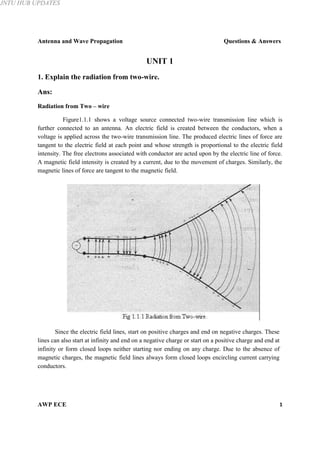
  • 1. JNTU HUB UPDATES Antenna and Wave Propagation Questions & Answers UNIT 1 1. Explain the radiation from two-wire. Ans: Radiation from Two – wire Figure1.1.1 shows a voltage source connected two-wire transmission line which is further connected to an antenna. An electric field is created between the conductors, when a voltage is applied across the two-wire transmission line. The produced electric lines of force are tangent to the electric field at each point and whose strength is proportional to the electric field intensity. The free electrons associated with conductor are acted upon by the electric line of force. A magnetic field intensity is created by a current, due to the movement of charges. Similarly, the magnetic lines of force are tangent to the magnetic field. Since the electric field lines, start on positive charges and end on negative charges. These lines can also start at infinity and end on a negative charge or start on a positive charge and end at infinity or form closed loops neither starting nor ending on any charge. Due to the absence of magnetic charges, the magnetic field lines always form closed loops encircling current carrying conductors. AWP ECE 1
  • 2. JNTU HUB UPDATES Antenna and Wave Propagation Questions & Answers The distribution of charge property is exhibited by the electric field lines drawn between the two conductors. When a sinusoidal signal is applied at the source, the electric field between the conductors may be sinusoidal with a period of applied source. Electromagnetic waves are formed by the time-varying electric and magnetic fields between the conductors and which will travel along the transmission line shown in figure 1.1.1. The electromagnetic waves enter into the antenna with associated electric charges and corresponding currents. When a part of antenna structure is removed (as shown in figure (1.1.2)), by connecting the open ends of the electric lines, free space waves are formed. The free space waves are also periodic but a constant phase point ‘x0’ moves outwardly with the speed of light and travels a distance λ/2 (to ‘x1’) in the time of one-half a period. The constant phase point ‘x0’ moves faster than the speed of light but approaches the speed of light at points far away from the antenna. AWP ECE 2 JNTU HUB UPDATES
  • 3. JNTU HUB UPDATES Antenna and Wave Propagation Questions & Answers 2. Define and account for the presence of, (i). Radial power flow (ii) Radiation resistance for a short dipole (iii) Uniform current distribution. Ans: (i) Radial power flow Radial power flow represents the amount of power moving in radial direction, which corresponds to the power density associated with the electromagnetic fields of an antenna. The total power radiated can be calculated with the help of pointing vector (P) as, P = E x H Where, E = Electric field H = Magnetic field. Therefore Total radiated power, Pr = Pr2 Therefore, the integration involves combination of imaginary part and real part. The combination of imaginary and real power is known as "Complex Power". Radial power is the part of complex power moving in radial direction. It corresponds to the real radiated power. (ii) Radiation Resistance for a short dipole The resistance observed, (or) experienced by transmission line when it is terminated by a short dipole is known as radiation resistance of short dipole. General expression is, (Rr)short dipole = 80π2 (dl/λ)2 Where, dl = Length of the dipole λ = Operating wavelength. AWP ECE 3 JNTU HUB UPDATES
  • 4. JNTU HUB UPDATES Antenna and Wave Propagation Questions & Answers (iii) Uniform Current Distribution Uniform current distribution signifies that the current flowing through antenna is constant. Uniform current distribution is possible, when the size of the antenna is very small. If the size of antenna is finite, uniform current distribution is not possible. This is valid for only small length antennas. 3. What are principle planes? How the antenna beam width is defined in such planes? Ans: Principle planes These planes are used to describe the performance of antennas. Principle planes are classified into two types. They are, 1. E-plane pattern 2. H-plane pattern. 1.E-plane pattern E-plane pattern is defined as the plane containing electric field vector in the direction of maximum radiation. The E-plane pattern is shown in the figure 1.3.1 2. H-plane pattern H-plane pattern is defined as the plane containing magnetic field vector in the direction of maximum radiation. The H-plane pattern is shown in the figure 1.3.1 AWP ECE 4 JNTU HUB UPDATES
  • 5. JNTU HUB UPDATES Antenna and Wave Propagation Questions & Answers 4. Explain the following terms, (i) Beam width (ii) Omni directional pattern (iii)Side lobe level (iv)Field pattern of antenna Ans: (i) Beam Width It is used to measure the directivity of an antenna. In general antenna beam width is defined as “the angular width of the major lobe between the two directions at which maximum power is twice the radiated or received power. Beam width = (HPBW)Vertical x (HPBW)Horizontal B = θE 0 X θH 0 There are two factors effecting the beam width. They are, 1. Wavelength 2. Radiation pattern shape. (ii) Omnidirectional Pattern The radiation pattern which is distributed equally well in all directions is called as omnidirectional patterns. The antenna which exhibits such a property is known as omnidirectional antenna or nondirectional antenna (since it does not favour any particular direction). Figure 1.4.1 shows omnidirectional pattern with and without minor lobes. The omnidirectional pattern can be approximated by, U = |sin | ; 0≤θ≤π, 0≤Φ≤2π Where, n = Either integer or non integer value. This type of pattern is commonly associated with verticals, ground planes and other antenna types in which the radiator element is vertical with respect to the earth's surface. The approximated formula for directivity of an omnidirectional antenna with minor lobes can be calculated as, D0 = 101⁄ 0.0027 and, the directivity of an omnidirectional antenna without minor lobes can be calculated using, AWP ECE D0 = -172.4 + 191 0.818 1/ 5 JNTU HUB UPDATES
  • 6. JNTU HUB UPDATES Antenna and Wave Propagation Questions & Answers (iii) Side Lobe Level The ratio (in dB) of the amplitude at the peak of the main lobe to the amplitude at the peak of a side lobe is known as side lobe level. Where the side lobe is a radiation lobe in any direction other than the intended lobe. Normally a side lobe is adjacent to the main lobe and occupies the hemisphere in direction of main lobe. Usually, the side lobes are the largest of the minor lobes, figure 1.4.2 shows the linear plot of power patterns. The side lobe level can be reduced by tapering the edges of the aperture distribution at the expense of reduced directivity. The null between side lobes occur when the radiation pattern passes through the origin in the complex plane. Hence, adjacent side lobes are generally 1800 out of phase to each other. (iv) Field Pattern of Antenna There are two different types of field patterns of antenna namely. Far- field and near-field patterns. The near-field pattern is most commonly defined over a plane placed in front of the source or over a cylindrical or spherical surface enclosing it. The far-field pattern of an antenna may be determined experimentally at an antenna range. The near-field pattern may be found using a near-field scanner and the radiation pattern deduced from it by computation. AWP ECE 6 JNTU HUB UPDATES
  • 7. JNTU HUB UPDATES Antenna and Wave Propagation Questions & Answers The far -field pattern may be represented graphically as a plot of one of a number of related variables including, the field strength at a constant radius, the power per unit solid angle and the directive gain. The plotted quantity may be taken on a linear scale or in dB. 5. Define the terms, (i) Bandwidth (ii) Polarization (ii) Effective aperture area. Ans: (i) Bandwidth There is the range of frequencies for which the antenna maintains certain specific characteristics. It is given as, Bandwidth, ω = ω2-ω1 Δω = ωr/Q Where, ωr = Angular resonating frequency Q = Quality factor. (ii) Polarization The time varying behavior of the electric field strength vector at a fixed point in space is known as polarization of a uniform plane wave. Consider a plane wave is travelling in the z-direction with ‘E’ and ‘H’ components lying in the xy plane. The wave is said to be polarized in x-direction, if Ex ≠ 0 and E y = 0. Similarly, the wave is said to be polarized in y-direction, if Ex = 0 and E y ≠0 . The resultant electric field has a direction dependent on the relative magnitudes of Ex and Ey, if both the fields are present and are in phase. The direction with the x-axis is given by, θ = tan-1 [Ey/Ex] A linearly polarized wave in which the direction of the resultant vector is constant with time. An elliptically polarized wave in which the two field components are not equal and are in out of phase (i.e., if they are reached maximum values at different instances) and the resultant vector direction is varied with time. A circularly polarized wave in which the two field components are having equal magnitudes and a 90° phase difference. AWP ECE 7 JNTU HUB UPDATES
  • 8. JNTU HUB UPDATES Antenna and Wave Propagation Questions & Answers (iii) Effective Aperture Area Effective area is defined as the ratio of power received at the antenna load terminal to the poynting vector (P), of the incident wave. Effective area is also known as effective aperture (or) capture area. Effective Area, ⁄( Ae ) = Ae = ⁄ W h e r e , W = Power received (watts) P = Poynting vector (watts/m2 ) 6. Distinguish between directive gain and power gain. Ans: Differences between Directive Gain and Power Gain Directive Gain (Gd) Power Gain (Gp) 1. Directive gain in a given direction is 1. Power gain is defined as the ratio of defined as the ratio of the radiation radiation intensity in given direction to the intensity in that direction to the average total input power. radiated power. 2. In the calculation of directivity, the 2. In the calculation of power gain, the radiated power is considered for the power fed to the antenna is considered. directive antenna. 3. The concept of directive gain is most 3. The concept of power gain is most important to a radio system designer.convenient to antenna theorist because, it depends only up on the antenna pattern. 4. The power gain is depends on the power 4. The directive gain is solely depends on the input to the antenna, antenna losses or the distribution of radiated power in space. power consumed in a terminating resistance. 5. It is basically measured in dB 5. It is also basically measured in dB Gd (dB) = 10 log Gp (dB) = 10log AWP ECE 8 JNTU HUB UPDATES
  • 9. JNTU HUB UPDATES Antenna and Wave Propagation Questions & Answers 7. Draw the dual characteristics of an antenna. Ans: Dual Characteristics of an Antenna The duality of an antenna specifies a circuit device on one band and a space device on the other hand. Figure 1.7.1 shows the schematic diagram of basic antenna parameters, illustrating dual characteristics of an antenna. 8. Explain briefly radiation mechanism in single wire antenna? Ans: Radiation Mechanism in Single Wire Antenna Let us consider a single wire and a circular cross sectional cylinder with volume charge density, qv. AWP ECE 9 JNTU HUB UPDATES
  • 10. JNTU HUB UPDATES Antenna and Wave Propagation Questions & Answers The field is distributed in a wire of cross-sectional area, A and volume, V as shown in figure 1.8.1. The current density, Jz over the cross-section of the wire is, Jz = qv.Vz ….(1) Where, given by, qv = Volume charge density (columbs/m3 ) Vz = Velocity in z-direction. The radius of the wire is zero, and then the current in the wire is Iz = q1Vz …..(2) If the current is time varying then the equation (2), dIz/dt = q1 dVz/dt = q1.az Where, az is the acceleration. Hence, (i) There is no radiation for a stationary charge (ii) If a charge has uniform velocity and the wire is straight and infinite in extent, there is no radiation unless the wire is curried, bent, discontinued, terminated or truncated. (iii) If the charge is oscillating in a time-motion, it develops radiation at the surrounding even for straight wire. 9. Write short note on Normalized field pattern. Ans: Normalized Field Pattern Normalized field pattern is the field pattern, which is obtained by dividing a field component by its maximum value. It is a dimensionless number and whose maximum value is one. Normalized field pattern for an electric field is expressed as, Normalized Field Pattern, Eθ(θ,Φ) = Eθ(θ,Φ)/ Eθ(θ,Φ)max Where, Eθ(θ,Φ) = Electric field component Eθ(θ,Φ)max = Maximum value of electric field component. Figure 1.9.1 shows the normalized field pattern for the electric field ‘E’. For Eθ(θ,Φ)n = 1/√2 = 0.707, the half power levels occurs at those angles θ and Φ. The shape normalized field pattern is independent of distance for, 1. The distance that are large compared to the size of the an antenna. AWP ECE 10 JNTU HUB UPDATES
  • 11. JNTU HUB UPDATES Antenna and Wave Propagation Questions & Answers 2. The distance that are large compared to the wavelength. 10. Explain the following, i. Beam area ii. Radiation intensity iii. Beam efficiency iv. Directivity. Ans: i. Beam Area In polar two-dimensional coordinates an incremental area dA on the surface of sphere is the product of the length r dθ in the θ direction and r sin θ dΦ in the Φ direction as shown in figure 1.10.1. Thus, dA = (rdθ) (r sinθ dΦ) = r2 dΩ Where, dΩ = solid angle expressed in steradians. AWP ECE 11 JNTU HUB UPDATES
  • 12. JNTU HUB UPDATES The area of the strip of width r dθ extending around the sphere at a constant angle θ is given by (2πr sin θ) (r dθ). Integrating this for θ values from 0 to π yields the area of the sphere. Thus, Area of sphere = 2πr2 sin = 2πr2 [-cosθ] π = 4πr2 Where, 0 4π = Solid angle subtended by a sphere The beam area or beam solid angle or Ω A of an antenna is given by the integral of the normalized power pattern over a sphere Beam area, Ω A = , Ω (sr) Where, dΩ = sinθ dθ dΦ ii. Radiation Intensity The power radiated from an antenna per unit solid angle is called the radiation intensity U (watts per steradian or per square degree). The normalized power pattern of the previous section can also be expressed in terms of this parameter as the ratio of the radiation intensity U ( θ, Φ), as a function of angle, to its maximum value. Thus, Pn(θ,Φ) = U(θ,Φ)/U(θ,Φ)max = S(θ,Φ)/S(θ,Φ)max Whereas the Poynting vector S depends on the distance from the antenna (varying inversely as the square of the distance), the radiation intensity U is independent of the distance, assuming in both cases that we are in the far field of the antenna. AWP ECE 12 JNTU HUB UPDATES
  • 13. JNTU HUB UPDATES Antenna and Wave Propagation Questions & Answers iii. Beam Efficiency The beam area Q A (or beam solid angle) consists of the main beam area (or solid angle) ΩM plus the minor-lobe area (or solid angle) Ω m . Thus, ΩA = ΩM + Ωm The ratio of the main beam area to the (total) beam area is called the (main) beam efficiency εM. Thus, Beam Efficiency = εM = ΩM / ΩA (dimensionless) The ratio of the minor-lobe area ( Ωm ) to the (total) beam area is called the stray factor. Thus, εm = Ωm / ΩA = stray factor. iv. Directivity It is defined as the ratio of maximum radiation intensity of subject or test antenna to the radiation intensity of an isotropic antenna. (or) Directivity is defined as the ratio of maximum radiation intensity to the average radiation intensity. Directivity, D = Umax/Uavg = Directivity (D) in terms of total power radiated is, D = 4π x Maximum radiation intensity/ Total power radiated AWP ECE 13 JNTU HUB UPDATES