Electronic Voting Machine
•
52 recomendaciones•25,184 vistas

Seminar report and ppt on Electronic Voting Machine, EVM Visit http://seminarlinks.blogspot.in/ to download

Recomendados
Recomendados
Más contenido relacionado
Más de Seminar Links
Más de Seminar Links (20)
Último
Último (20)
Electronic Voting Machine
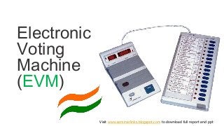
- 1. Electronic Voting Machine (EVM) Visit www.seminarlinks.blogspot.com to download full report and ppt
- 2. Electronic Voting Machines ("EVM") are being used in Indian General and State Elections to implement electronic voting in part from 1999 elections and in total since 2004 elections. The EVMs reduce the time in both casting a vote and declaring the results compared to the old paper ballot system.
- 3. The EVMs were devised and designed by Election Commission of India in collaboration with two Public Sector undertakings viz., Bharat Electronics Limited, Bangalore and Electronics Corporation of India Limited, Hyderabad. In 1980, Mr. M. B. Haneefa designed the first Indian voting machine. His original design was exhibited to the public in six Government Exhibitions of Tamil Nadu, viz.: Madras (Chennai), Trichy, Coimbatore, Salem, Madurai and Tirunelveli. Remarkably, the voting machine was designed using only Integrated Circuits. EVMs were first used in 1981 in the by-election to North Paravur Assembly Constituency of Kerala for a limited number of polling stations (50 polling stations).
- 4. It is a reliable machine for conducting Elections. Has mainly 2 units: Ballot and Control Units. Operates on a Special Battery Tamper-proof Information recorded is retained in memory even when the battery is removed. Easily portable
- 5. Each Unit has been provided a casing. Once opened 3 things will be found: Control unit Ballot Unit Interconnecting Cable. Control Unit Ballot Unit Cable
- 6. Block diagram of EVM
- 7. EVMs are powered by an ordinary 6 volt alkaline battery They are Special batteries supplied separately These batteries have a Seal which should be removed before Using They have an active lifetime of 24 hours.
- 8. Ballot Unit Used by Voters for casting their votes. It consists of : BJP Congress Interconnecting Cable Ballot paper Screen Ready Lamp Candidate buttons(16) Candidate lamps(16)
- 9. Block diagram of ballot unit
- 10. To start with EVM Ballot unit is divided into 2 main sub sections:- 1) Motherboard board circuit 2) votecast LED and feedback panel.
- 11. Motherboard circuitry consists of following components. : Microcontroller Crystal Oscillator Optocoupler Buzzer Amplifier Resistor and a capacitor network for reset circuit of microcontroller. Votecast LED panel— A vote cast LED panel is a section which will be at the voters end for the voters to cast their votes. Here there are following components: 8 push to on switch 8 Red LED’s 8 green LED’s Additionally one more red LED and push to on switch has been added for a machine ready signal. Ideally this push to on switch is at the control panel but since here we have only a ballot unit therefore this button is mounted on this panel.
- 13. It is a flat protected cable and who’s one end is connected to the Ballot Unit permanently while the other end is attached VIA a connector to the Control unit. Make sure that the cable is properly secured to the Control unit. Cable TOP 15 PIN CONNECTOR SPRING CLIPS
- 14. Ready lamp glows GREEN when Ballot button on Control Unit is pressed by P.O. to enable voting. Goes Off when voter has finished casting his vote. Slide Switch Panel used to set anyone of the 4 options: 1,2,3,or 4. ie. For 1 ballot unit Switch is set to 1 and so on… Candidates lamp: glows RED when the voter has pressed the candidate button pertaining to the candidate of his choice. Ballot paper Screen: where the Ballot Paper with name, sr,no., Symbol of contesting candidates is inserted. Masking tabs provided under the Candidate buttons. So depending on the no. of candidates contesting, the tabs are unmasked. Ones not in use are masked.
- 15. CONTROL UNIT Controls the polling process. Operated only by P.O. Consists of: Busy lamp ON lamp Display Section Candidate Set Section Result Section Ballot Section 4 sections in all
- 16. Display section has: 2 lamps: On and Busy ; also 2 display panels: one of 2 digit and other of 4 digit displays. Candidate Set Section: has a cover opening l-r: we see a left compartment which accommodates the Battery and the right one a Red Cad Set button. This section is closed by thread Seal. Result Section: also has same cover as above. On opening we find the left side has a Black Close button while right side has inner compartment with its own door. One button her is result 1 button. used for one type of election only: like only single Poll. Result 2 used for both types conducted at the same time, Clear button. Provision kept for a seal in the cover of this inner compt. and thread seal too. Ballot Section: has 2 buttons , a gray Total button and a large Ballot button. Bottom of C.Unit also open for plugging the cable from b.unit and a power switch to switch EVM On/Off.
- 17. On lamp: in display section will glow GREEN when Control Unit Power switch is put ON, indicating EVM is ready for use. Busy lamp: in display section glows RED when Ballot button is pressed by P.O. to enable voter to cast vote. Goes Off when over.
- 18. 2 DIGIT DISPLAY LE: link error: ie. Interconnecting cable not properly connected. PE: Pressed error, where any of the candidates buttons in Ballot unit are jammed or kept pressed. Er: Memory Error: Control unit not fit to use.
- 19. 4 DIGIT DISPLAY no: indicates a button pressed on Control unit is pressed out of sequence. End: End of display sequence after pressing Close , Result or clear button. Full : indicates max no.of votes for which machine is designed. 9999 is the max.
- 20. nP 1 : machine set for Single poll only. Cd 6 : machine set for 6 candidates. to 1234: total no. of votes casted = 1234 06 234: candidate 6 has 234 votes in his favor.
- 21. A beep of not less than 2 seconds after a voter casted his vote. A beep of 1 second, when displaying information on display units. Short interrupted beeps to show malfunctioning , disconnection, errors….
- 22. Cand Set: used to set EVM for no. of candidates contesting the election. Clear: pressed before start of a poll: to clear machine of recorded informations. Used when election is over/ not done w/o orders. Ballot: enables voter to record his vote: so once pressed: the BUSY lamp goes Red, Ready lamp of C.Unit goes Green and voter can now caste his vote. Then Pressed again to allow next voter to record his vote…. Total: shows no. of candidates and total no. of votes recorded so far. Pressed at anytime: to see the same. But not when Busy lamp is ON.
- 23. Close: Once pressed: no further voting can take place. Only pressed at the end of the Poll. When Pressed the no. of polls, no. of candidates, total votes polled and the word end will be displayed. Result: when EVM is used for simultaneous poll: ie Lok Sabha & Legislative assembly polls , both Result 1 & 2 are used ie. R1 for Loksabha,R2 for LA. When only single Poll, only R1 is used. In our case Only Result 1 USED. When Pressed it will display in sequence the no. of candidates, total no. of votes polled, votes for each candidates. The finally displays END. This button can be pressed as reqd.
- 25. It is easier to transport the EVMs compared to ballot boxes. The vote-counting is very fast and the result can be declared within 2 to 3 hours as compared to 30–40 hours, on an average, under the ballot- paper system. Easy to cast vote. Bogus voting has been greatly reduced by the use of EVMs. Quick replacement The Control Unit can store the result in its memory for 10 years and even more. With EVMs, there are much less incidences of invalid votes. Saves 10,000 tons of ballot paper (roughly 200,000 trees).
- 26. Nepal, Bhutan, Namibia and Kenya have purchased India-manufactured EVMs. Fiji is expected to use Indian EVMs in the next elections in 2014. In 2013, the Election Commission of Namibia acquired 1700 control units and 3500 ballot units from India's Bharat Electronics Limited; these units will be used in the regional and presidential elections in 2014
- 27. THE EVM Ballot Unit Control Unit Visit www.seminarlinks.blogspot.com to download full report and ppt