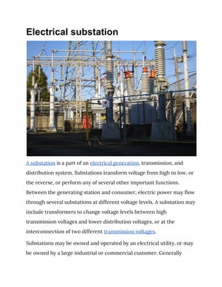
A substation is a part of an electrical generation, transmission, and distribution system. Substations transform voltage from high to low, or the reverse, or perform any of several other important functions.
Mifty kit IN Salmiya (+918133066128) Abortion pills IN Salmiyah Cytotec pills
Electrical substation
1. Electrical substation
A substation is a part of an electrical generation, transmission, and
distribution system. Substations transform voltage from high to low, or
the reverse, or perform any of several other important functions.
Between the generating station and consumer, electric power may flow
through several substations at different voltage levels. A substation may
include transformers to change voltage levels between high
transmission voltages and lower distribution voltages, or at the
interconnection of two different transmission voltages.
Substations may be owned and operated by an electrical utility, or may
be owned by a large industrial or commercial customer. Generally
2. substations are unattended, relying on SCADA for remote supervision
and control.
AddressBazar.com is an Bangladeshi Online Yellow Page. From here you
will find important and necessary information of various Electrical
substation equipment related organizations in Bangladesh.
The word substation comes from the days before the distribution
system became a grid. As central generation stations became larger,
smaller generating plants were converted to distribution stations,
receiving their energy supply from a larger plant instead of using their
own generators. The first substations were connected to only one
power station, where the generators were housed, and were
subsidiaries of that power station.
Types
Substations may be described by their voltage class, their applications
within the power system, the method used to insulate most
connections, and by the style and materials of the structures used.
These categories are not disjointed; for example, to solve a particular
problem, a transmission substation may include significant distribution
functions.
Transmission substation
A transmission substation connects two or more transmission lines.
The simplest case is where all transmission lines have the same voltage.
3. In such cases, substation contains high-voltage switches that allow
lines to be connected or isolated for fault clearance or maintenance. A
transmission station may have transformers to convert between two
transmission voltages, voltage control/power factor correction devices
such as capacitors, reactors or static VAR compensators and equipment
such as phase shifting transformers to control power flow between two
adjacent power systems.
Transmission substations can range from simple to complex. A small
"switching station" may be little more than a bus plus some circuit
breakers. The largest transmission substations can cover a large area
(several acres/hectares) with multiple voltage levels, many circuit
4. breakers, and a large amount of protection and control equipment
(voltage and current transformers, relays and SCADA systems). Modern
substations may be implemented using international standards such as
IEC Standard 61850.
Distribution substation
A distribution substation transfers power from the transmission system
to the distribution system of an area. It is uneconomical to directly
connect electricity consumers to the main transmission network,
unless they use large amounts of power, so the distribution station
reduces voltage to a level suitable for local distribution.
The input for a distribution substation is typically at least two
transmission or sub-transmission lines. Input voltage may be, for
example, 115 kV, or whatever is common in the area. The output is a
number of feeders. Distribution voltages are typically medium voltage,
between 2.4 kV and 33 kV, depending on the size of the area served and
the practices of the local utility. The feeders run along streets overhead
(or underground, in some cases) and power the distribution
transformers at or near the customer premises.
In addition to transforming voltage, distribution substations also isolate
faults in either the transmission or distribution systems. Distribution
substations are typically the points of voltage regulation, although on
5. long distribution circuits (of several miles/kilometers), voltage
regulation equipment may also be installed along the line.
The downtown areas of large cities feature complicated distribution
substations, with high-voltage switching, and switching and backup
systems on the low-voltage side. More typical distribution substations
have a switch, one transformer, and minimal facilities on the
low-voltage side.
Collector substation
In distributed generation projects such as a wind farm or Photovoltaic
power station, a collector substation may be required. It resembles a
distribution substation although power flow is in the opposite
6. direction, from many wind turbines or inverters up into the
transmission grid. Usually for economy of construction the collector
system operates around 35 kV, although some collector systems are 12
KV, and the collector substation steps up voltage to a transmission
voltage for the grid. The collector substation can also provide power
factor correction if it is needed, metering, and control of the wind farm.
In some special cases a collector substation can also contain an HVDC
converter station.
Collector substations also exist where multiple thermal or
hydroelectric power plants of comparable output power are in
proximity. Examples for such substations are Brauweiler in Germany
and Hradec in the Czech Republic, where power is collected from
nearby lignite-fired power plants. If no transformers are required for
increasing the voltage to transmission level, the substation is a
switching station.
Converter substations
Converter substations may be associated with HVDC converter plants,
traction current, or interconnected non-synchronous networks. These
stations contain power electronic devices to change the frequency of
current, or else convert from alternating to direct current or the
reverse. Formerly rotary converters changed frequency to interconnect
two systems; nowadays such substations are rare.
7. Switching station
A switching station is a substation without transformers and operates
only at a single voltage level. Switching stations are sometimes used as
collector and distribution stations. Sometimes they are used for
switching the current to back-up lines or for parallelizing circuits in
case of failure. An example is the switching stations for the HVDC
Inga–Shaba transmission line.
A switching station may also be known as a switchyard, and these are
commonly located directly adjacent to or nearby a power station. In
this case the generators from the power station supply their power into
the yard onto the Generator Bus on one side of the yard, and the
8. transmission lines take their power from a Feeder Bus on the other side
of the yard.
An important function performed by a substation is switching, which is
the connecting and disconnecting of transmission lines or other
components to and from the system. Switching events may be planned
or unplanned. A transmission line or other component may need to be
de-energized for maintenance or for new construction, for example,
adding or removing a transmission line or a transformer. To maintain
reliability of supply, companies aim at keeping the system up and
running while performing maintenance. All work to be performed, from
routine testing to adding entirely new substations, should be done
while keeping the whole system running.
Unplanned switching events are caused by a fault in a transmission line
or any other component, for example:
● a line is hit by lightning and develops an arc,
● a tower is blown down by high wind.
The function of the switching station is to isolate the faulty portion of
the system in the shortest possible time. De-energizing faulty
equipment protects it from further damage, and isolating a fault helps
keep the rest of the electrical grid operating with stability.
Railways
Electrified railways also use substations, often distribution substations.
In some cases a conversion of the current type takes place, commonly
9. with rectifiers for direct current (DC) trains, or rotary converters for
trains using alternating current (AC) at frequencies other than that of
the public grid. Sometimes they are also transmission substations or
collector substations if the railway network also operates its own grid
and generators to supply the other stations.
Mobile substation
A mobile substation is a substation on wheels, containing a transformer,
breakers and buswork mounted on a self-contained semi-trailer, meant
to be pulled by a truck. They are designed to be compact for travel on
public roads, and are used for temporary backup in times of natural
disaster or war. Mobile substations are usually rated much lower than
permanent installations, and may be built in several units to meet road
travel limitations.
Design
Elements of a substation
Substations generally have switching, protection and control
equipment, and transformers. In a large substation, circuit breakers are
used to interrupt any short circuits or overload currents that may
occur on the network. Smaller distribution stations may use recloser
circuit breakers or fuses for protection of distribution circuits.
Substations themselves do not usually have generators, although a
power plant may have a substation nearby. Other devices such as
10. capacitors, voltage regulators, and reactors may also be located at a
substation.
Substations may be on the surface in fenced enclosures, underground,
or located in special-purpose buildings. High-rise buildings may have
several indoor substations. Indoor substations are usually found in
urban areas to reduce the noise from the transformers, for reasons of
appearance, or to protect switchgear from extreme climate or pollution
conditions.
A grounding (earthing) system must be designed. The total ground
potential rise, and the gradients in potential during a fault (called touch
and step potentials), must be calculated to protect passers-by during a
11. short-circuit in the transmission system. Earth faults at a substation
can cause a ground potential rise. Currents flowing in the Earth's
surface during a fault can cause metal objects to have a significantly
different voltage than the ground under a person's feet; this touch
potential presents a hazard of electrocution. Where a substation has a
metallic fence, it must be properly grounded to protect people from
this hazard.
The main issues facing a power engineer are reliability and cost. A good
design attempts to strike a balance between these two, to achieve
reliability without excessive cost. The design should also allow
expansion of the station, when required.
Location selection
Selection of the location of a substation must consider many factors.
Sufficient land area is required for installation of equipment with
necessary clearances for electrical safety, and for access to maintain
large apparatus such as transformers.
Where land is costly, such as in urban areas, gas insulated switchgear
may save money overall. Substations located in coastal areas affected
by flooding and tropical storms may often require an elevated structure
to keep equipment sensitive to surges hardened against these
elements. The site must have room for expansion due to load growth or
12. planned transmission additions. Environmental effects of the substation
must be considered, such as drainage, noise and road traffic effects.
The substation site must be reasonably central to the distribution area
to be served. The site must be secure from intrusion by passers-by,
both to protect people from injury by electric shock or arcs, and to
protect the electrical system from misoperation due to vandalism.
Design diagrams
The first step in planning a substation layout is the preparation of a
one-line diagram, which shows in simplified form the switching and
protection arrangement required, as well as the incoming supply lines
and outgoing feeders or transmission lines. It is a usual practice by
many electrical utilities to prepare one-line diagrams with principal
13. elements (lines, switches, circuit breakers, transformers) arranged on
the page similarly to the way the apparatus would be laid out in the
actual station.
In a common design, incoming lines have a disconnect switch and a
circuit breaker. In some cases, the lines will not have both, with either a
switch or a circuit breaker being all that is considered necessary. A
disconnect switch is used to provide isolation, since it cannot interrupt
load current. A circuit breaker is used as a protection device to
interrupt fault currents automatically, and may be used to switch loads
on and off, or to cut off a line when power is flowing in the 'wrong'
direction. When a large fault current flows through the circuit breaker,
this is detected through the use of current transformers. The
magnitude of the current transformer outputs may be used to trip the
circuit breaker resulting in a disconnection of the load supplied by the
circuit break from the feeding point. This seeks to isolate the fault point
from the rest of the system, and allow the rest of the system to
continue operating with minimal impact. Both switches and circuit
breakers may be operated locally (within the substation) or remotely
from a supervisory control center.
With overhead transmission lines, the propagation of lightning and
switching surges can cause insulation failures into substation
equipment. Line entrance surge arresters are used to protect
substation equipment accordingly. Insulation Coordination studies are
14. carried out extensively to ensure equipment failure (and associated
outages) is minimal.
Once past the switching components, the lines of a given voltage
connect to one or more buses. These are sets of busbars, usually in
multiples of three, since three-phase electrical power distribution is
largely universal around the world.
The arrangement of switches, circuit breakers, and buses used affects
the cost and reliability of the substation. For important substations a
ring bus, double bus, or so-called "breaker and a half" setup can be
used, so that the failure of any one circuit breaker does not interrupt
power to other circuits, and so that parts of the substation may be
de-energized for maintenance and repairs. Substations feeding only a
single industrial load may have minimal switching provisions, especially
for small installations.
Once having established buses for the various voltage levels,
transformers may be connected between the voltage levels. These will
again have a circuit breaker, much like transmission lines, in case a
transformer has a fault (commonly called a "short circuit").
Along with this, a substation always has control circuitry needed to
command the various circuit breakers to open in case of the failure of
some component.