SlideShare una empresa de Scribd logo
1 de 2
Descargar para leer sin conexión
Harness Connector Location Chart
Connector
Machine
Location
Harness And/Or
Components
Schematic
Location
A-6Y7376
Operator Monitor (EMS)
E-4
A - 6Y7376
Diagnostic Connector
F-7
9 Contacts
A - 6Y7376
C - 7T8326
D-6
G - 9U9458 Attachment
H - 9U9463 Attachment
C-7
G - 9U9458 Attachment
H - 9U9463 Attachment
C-B
G - 9U9458
Attachment Radio
B-4
7Contacts
A - 6Y7376
B-1011339
E-3
A - 6Y7376
B-1011339
D-3
A - 6Y7376
E - 9U9407
A-5
A - 6Y7376
Voltage Converter
E-3
5 Contacts
A - 6Y7376
M-6I8611
B-5
A-6Y7376
C-7T8326
D-5
A-6Y7376
G - 9U9458 Attachment
D-6
A - 6Y7376
N - 9W1816 Attachment
C-3
A - 6Y7376
Y - 6Y3416 Attachment
C-3
Machine locations are repeated for connectors located close together.
* = Connector is located at the component.
A = Connector in dash area.
B = Connector at relay panel.
D ¹ = Connector in headliner of operators compartment.
20 Contacts
8 Contacts
6 Contacts
4 Contacts
A
A
A
A
A
SENR4955
February 1993
D6H Series II Tractor
Electrical System
4RC5500-UP
6FC5500-UP
8FC5500-UP
1KD5500-UP
2KD5500-UP
3ED5500-UP
3ZF5500-UP
4YF5500-UP
5HF5500-UP
6CF5500-UP
6CF5500-UP
2TG5500-UP
3YG5500-UP
4GG5500-UP
4LG5500-UP
1FJ5500-UP
8ZHJ1-UP
9KJ1-UP
2DK5500-UP
5KK1-UP
6CK1-UP
7ZK1-UP
8KK1-UP
8SK1-UP
9LK1-UP
9RK1-UP
1YL1-UP
2BL1-UP
2TL1-UP
Printed in U.S.A.
©1993 Caterpillar
All Rights Reserved
A
3
4
5
6
8
9
10
11
12
14
15
13
16
B
C
D
1
217
18
19
7
A
3
4
5
6
8
9
10
11
12
14
15
13
16
B
C
D
1
2
17
18
19
7
Machine Harness Connector And Component Locations
1
2
1
2
Component Location
Component
Schematic
Location
Machine
Location
Component
Schematic
Location
Machine
Location
Alarm - Action (EMS) D-8 1 Sender - Hydraulic Oil Temp (Gauge) A-6 11
Alarm - Backup E-9 C Sender - Power Train Oil Temp (Gauge) B-2 12
Alternator B-1 2 Solenoid - A/C Clutch B-2 13
Batteries F-3 3 Solenoid - Start Aid F-2 14
Breaker - Alternator (60A) E-7 B Switch - Backup Alarm (CBS) D-7 C
Breaker - Blower Motor F-5 B Switch - Backup Alarm (DS) E-7 C ¹
Converter - Voltage E-3 C Switch - Blower Motor (A/C) B-3 A
Filter - Alternator B-5 A Switch - Blower Motor (Heater) C-3 5
Fuse - Front Dash and Dome (10A) E-7 B Switch - Disconnect F-3 3
Fuse - Key (10A) F-7 B Switch - Engine Coolant Temp (EMS) C-2 9
Fuses E-6 B Switch - Engine Coolant Temp (Start Aid) D-2 9
Gauges B-5 A Switch - Engine Oil Pressure (EMS) C-2 15
Ground - Module D-4 A Switch - Flood Lamp B-6 A
Horns - Front F-1 4 Switch - Forward Horn B-6 16
Lamp - Action (EMS) D-6 A Switch - Front and Dash Lamp C-6 A
Meter - Service B-5 A Switch - Fuel Press (EMS) C-2 17
Monitor - Operator (EMS) D-4 A Switch - Hydraulic Oil Temp (EMS) A-6 11
Motor - Blower (Heater) B-3 5 Switch - Key Start C-5 A
Motor - Starting A-2 6 Switch - Neutral Start (DD) B-9 18
Motor - Windshield Washer A-8 7 Switch - Neutral Start (PS with DS) D-7 C ¹
Motors - Blower (A/C) B-3, C-3 8 Switch - Neutral Start (PS with CBS) D-7 C
Motors - Wiper (Front & Left) C-4, E-7 D Switch - Power Train Filter Press (DS EMS) A-6 11
Motors - Wiper (Rear & Right) C-8, B-6 D Switch - Power Train Oil Temp (CBS EMS) C-2 19
Radios (12V & 24V) B-4 D ¹ Switch - Power Train Oil Temp (EMS) C-2 12
Relay - Main (Replaces Terminal Block) F-8 B Switch - Refrigerant Press F-2 13
Relay - Start F-6 B Switch - Start Aid C-6 A
Resistor - Blower Motor Speed (A/C) B-3 8 Switch - Test (EMS) D-6 A
Resistor - Blower Motor Speed (Heater) B-3 5 Switch - Thermostat (A/C) B-3 A
Resistor - Load F-6 B Switches - Wiper B-7, B-8 D ¹
Resistor - Starter to Diagnostic Connector B-2 6 Terminal Block F-6 B
Sender - Engine Coolant Temp (Gauge) C-2 9
Sender - Fuel (Gauge) D-9 10
A/C = Air Conditioning Machine locations are repeated for components located close
EMS = Electronic Monitoring System (operator monitor) together.
DS = Differential Steer Machines A = Components in dash area.
CBS = Clutch/Brake Steer Machines B = Components at relay panel.
PS = Power Shift C = Components in operator's left console.
PT = Power Train C ¹ = Components within diff steer control handle of operator's left
console.
D = Components in operator compartment.
D ¹ = Components in headliner of operators compartment.
Resistor, Sender and Solenoid Specifications
Part No. Component Description Resistance (Ohms)¹
2G0413 Resistor - Blower Motor Speed 5
9G1950 Resistor - Blower Motor Speed
Overall 2.0 ± .1
Tap 1.0±.05
7X6416 Resistor - Load 50 ± 5.0
6T2217 Resistor - Starter/Diagnostic Conn 150 ± 7.5
8T8813 Solenoid - A/C Clutch 14.4 ± 0.6
9G4365 Solenoid - Start Aid 6
¹ At room temperature unless otherwise noted.
Related Electrical Service Manuals
Form Number
Alternator (1005047):
Consist No.1005046 SENR2082
Consist No.1005045 SENR4130
Electronic Monitoring System SENR2945
Starting And Charging Systems SENR2947
Starting Motor (4N3181):
Consist No. 8C3651 (42-MT) SENR3581
Consist No. 9X4447 (F8) SENR4975
Consist No. 3T6305 (KE) SENR3536
Title
Off Machine Switch Specification
Part No. Function Actuate Deactuate Contact Position
3T5825 Power Train Oil Temperature (EMS)
129.4 ± 2.8°C
(265 ± 5°F)
118.3°C MIN
(245°F MIN)
Normally Closed
7N9785 Engine Coolant Temperature (EMS)
107.2 ± 2.8°C
(225 ± 5°F)
91.0°C MIN
(196°F MIN)
Normally Closed
7T0988 Engine Oil Pressure (EMS)
62 ± 21 kPa
(9.0 ± 3.0 psi)
38 ± 21 kPa
(5.0 ± 3.0 psi)
Normally Open
8N1693 Engine Coolant Temperature (Start Aid)
37.8 ± 2.8°C
(100 ± 5°F)
26.7°C MIN
(80°F MIN)
Normally Closed
8N2248
Hydraulic Oil Temperature
(Differential Steer EMS)
101.7 ± 2.8°C
(215 ± 5°F)
93.3°C MIN
(200°F MIN)
Normally Closed
8T8639 Refrigerant Pressure (A/C)
344.5 ± 34.5 kPa
(50 ± 5 psi)
172.3 ± 21 kPa
(25 ± 3 psi)
Normally Open
9G1300
Hydraulic Oil Temperature
(Clutch/Brake Steer EMS)
110.0 ± 2.8°C
(230 ± 5.0°F)
101.7°C MIN
(215°F MIN)
Normally Closed
9G3341
Power Train Oil Temperature
(Clutch/Brake Steer EMS)
51.7 ± 2.8°C
(125 ± 5°F)
43.0°C MIN
(110°F MIN)
Normally Closed
9W3187 Fuel Pressure (EMS)
93 ± 21 kPa
(13.5 ± 3.0 psi)
69 ± 21 kPa
(10.0 ± 3.0 psi)
Normally Closed
9X7781
Power Train Filter Pressure (EMS)
(Differential Steer EMS)
210 ± 70 kPa
(30 ± 10 psi)
—
—
Normally Open
Wire Description
Wire
Number
Wire
Color
Description
Power Circuits
101 RD BAT
102 BU HD LMP
105 BR KEY SW
108 BU AUX CKT
109 OR ALT OUTPUT(+) TERM.
112 PU MAIN POWER RELAY OUTPUT
113 OR OPR MON PANEL B+ SWITCHED
114 GN WARNING HORN (FORWARD)
116 BR AUX CKT
121 YL BACKUP ALARM TO LAMP
123 WH AUX CKT
124 GN A/C
129 BU AUX CKT
Ground Circuits
200 BK MAIN CHASSIS
201 BK OPR MON PANEL CMS
203 BK CHASSIS DIAGNOSTIC
207 BK STARTER DIAGNOSTIC
Basic Machine Circuits
301 BU STARTER NO.1 SOL
302 OR STARTER NO.1 RESISTOR TO DIAGNOSTIC
304 WH STARTER RELAY NO.1 OUTPUT
306 GN STARTER RELAY COIL TO NEUT START SW
307 OR KEY SW TO NEUT START SW
308 YL MAIN POWER RELAY COIL
310 PU START AID SW TO START AID SOL
311 WH START AID SOL TO TEMP SW
321 BR BCKP ALARM LAMP
322 GY WARNING HORN (FORWARD)
Monitoring Circuits
403 GN ALTERNATOR (R) TERM.
404 YL OPR MON HYD OIL TEMP
405 GY OPR MON OIL PRESS. (LO SETTING)
406 PU OPR MON COOLANT TEMP
410 WH OPR MON ACTION ALARM
411 PK OPR MON ACTION LAMP
413 BR OPR MON FUEL PRESS.
415 GN OPR MON TEST SW
424 GY OPR MON POWER TRAIN TEMP
426 BR OPR MON POWER TRAIN OIL FILTER
441 OR ENG COOLANT TEMP GAGE
442 GY HYD SYSTEM TEMP GAGE
443 YL POWER TRAIN TEMP GAGE
447 PK FUEL LEVEL GAGE
Accessory Circuits
500 BR WIPER - FRONT (PARK)
501 GN WIPER - FRONT (LO)
502 OR WIPER - FRONT (HI)
503 BR WIPER - REAR (PARK)
504 YL WIPER - REAR (LO)
505 BU WIPER - REAR (HI)
508 PU RADIO SPEAKER - LEFT
509 WH RADIO SPEAKER - LEFT (COMMON)
510 YL WASHER - PRIMER
511 BR RADIO SPEAKER - RIGHT
512 GN RADIO SPEAKER - RIGHT (COMMON)
513 OR A/C COMPRESSOR/REFRIGERANT PRESS. SW
515 GY BLOWER MOTOR (HI)
516 GN BLOWER MOTOR (MEDIUM)
517 BU BLOWER MOTOR (LO)
521 YL A/C SW TO REFRIGERANT SW
522 WH A/C CLUTCH TO THERMOSTAT SW
523 BR WIPER - LEFT (PARK)
524 BU WIPER - LEFT (LO)
525 GY WIPER- LEFT (HI)
526 YL WIPER - RIGHT (PARK)
527 GN WIPER - RIGHT (LO)
528 PK WIPER - RIGHT (HI)
592 BU DC/DC CONVERTER POWER OUTPUT
A513 PK DC/DC CONVERTER MEMORY OUTPUT
Lighting Circuits
600 BR DASH BASIC
608 GN FLOOD REAR
609 YL FLOOD SIDE
610 OR HEAD LAMP BASIC
T
Normally open switch that will close with an increase of a specific condition (temp-press-etc.).
Normally open switch that is closed due to an applied condition, and will open again with a
specific decrease in that condition.
Normally closed switch that will open with an increase of a specific condition.
Normally closed switch that is open due to an applied condition, and will close again
with a specific decrease in that condition.
The circle indicates that the component has screw terminals and a wire can be disconnected
from it.
No circle indicates that the wire cannot be disconnected from the component.
This indicates that the component has a wire connected to it that is connected to ground.
This indicates that the component does not have a wire connected to ground. It is grounded
by being fastened to the machine.
Electrical Schematic Symbols And Definitions
Pressure
Symbol
Temperature
Symbol
Level
Symbol
Flow
Symbol
A AA
2
A AA
1
2
325-PK-14
C A
325-PK-14
200-BK-14
T
FUSE - A component in an electrical circuit that will open the circuit if too much current flows
through it.
REED SWITCH - A switch whose contacts are controlled by a magnet. A magnet closes the
contacts of a normally open reed switch; it opens the contacts of a normally closed reed switch.
SENDER - A component that is used with a temperature or pressure gauge. The sender
measures the temperature or pressure. Its resistance changes to give an indication to the
gauge of the temperature or pressure.
RELAY (Magnetic Switch) - A relay is an electrical component that is activated by electricity.
It has a coil that makes an electromagnet when current flows through it. The electromagnet
can open or close the switch part of the relay.
CIRCUIT BREAKER (C/B) - A component in an electrical circuit that will open the circuit if too
much current flows through it. This does not destroy the circuit breaker and it can be reset to
become part of the circuit again.
SOLENOID - A solenoid is an electrical component that is activated by electricity. It has a coil
that makes an electromagnet when current flows through it. The electromagnet can open or
close a valve or move a piece of metal that can do work.
Harness And Wire Electrical Schematic Symbols
SocketPin
Pin or Socket
Number
Wire, Cable, or Harness
Assembly Identification
Single Wire
Connector
Circuit Number
Identification
Wire
Gauge
Wire
Color
Plug Receptacle
9X-1123
Component
Part Number
Electrical Schematic Symbols And Definitions
1
1 1
2 2
Typical representation of a
Sure-Seal connector. The
plugand receptacle contain
both pins and sockets.
Typical representation of a
Deutsch connector. The
plug contains all sockets
and the receptacle contains
all pins.
MAGNETIC LATCH SOLENOID - A magnetic latch solenoid is an electrical component that is
activated by electricity and held latch by a permanent magnet. It has two coils (latch and unlatch)
that make electromagnet when current flows through them. It also has an internal switch that places
the latch coil circuit open at the time the coil latches.
1
1
2
D ¹
D ¹
D ¹
*
B
A
*
306-GN1
2
8
3
1
4
5
6
7
2
6
4
1
1
2
7
3
6
2
9
5
4
8
1
5
6
4
1
7
3
2
6
5
4
3
2
1
3
2
1
1
2
4
5
6
3
4
1
2
3
8
7
5
1
2
F
E
D
9 8 7
C
B
A
9 8 7
6 5 4
6 5
3 2 1
F
E
D
3 2 1
C
B
A
3
6
5
4
2
6
4
3
2
5
3
2
1
2
1
3
2
1
2
1
2
3
5
4
1
1
2
1
3
1
P
200-BK
200-BK
200-BK
108-BU-14RADIO
102-BU-14
102-BU-14
108-BU-14
STARTER
RELAY
3E-0075
A
114-GN
129-BU
108-BU-14
123-WH
113-OR
BK-18
207-BK
302-OR
310-PU
101-RD-6
311-WH
201-BK
203-BK
102-BU-14
112-PU-14
112-PU
308-YL
308-YL
109-OR-6
200-BK
306-GN
A
A
AA
A
A
A
AA
A A
116-BR-14
A
A
A
A
A
A
A
A
A
A
BK-18
109-OR-14
109-OR-8
15A
308-YL
112-PU-14
MM
200-BK
LL
LOAD RESISTOR
7X-6416
410-WH
CIGAR LIGHTER
BLOWER MOTOR
BREAKER
3T-8728
20A
109-OR-6
200-BK
FUSE
HOLDER
4K-5122
TERMINAL BLOCK
6T-0751
ALT
CIRCUIT
BREAKER
9S-0173
200-BK
FRONT
DASH
DOME
FUSE
3K-8782
KEY
FUSE
3K-8782
10A
10A
LL
112-PU-14
200-BK
109-OR-6
A
112-PU-14
WIPER MOTORS
200-BK-14
308-YL
306-GN
200-BK-18
610-OR-18
BR
ALTERNATOR
FILTER
100-5052
GROUND
304-WH-8
124-GN-14
BR
BK
123-WH
200-BK
GR
L8
442-GY
442-GY
HYDRAULIC
OIL TEMP
GAGE
4W-0484
NOTE D
M
M
M
123-WH-18
200-BK-18
442-GY-18
442-GY442-GY-18
442-GY
442-GY
442-GY
C
442-GY
GRD
T
SEND
IGN
S
442-GY
442-GY
M
109-OR-6
200-BK
129-BU-14
HYDRAULIC
OIL TEMP
SENDER
8N-3844
515-GY-14
200-BK-14
OROPSHEATER
2
426-BR
201-BK
404-YL
4
109-OR-4
101-RD-6
201-BK
411-PK
415-GN
200-BK-14
200-BK
403-GN
405-GY
413-BR
406-PU
441-OR
201-BK
101-RD-6
404-YL
200-BK-14
426-BR
447-PK
322-GY
201-BK
200-BK
121-YL
321-BR
201-BK
522-WH-14
608-GN-14
114-GN
521-YL-14
322-GY
311-WH
521-YL-14
310-PU
610-OR-14
403-GN
522-WH-14
311-WH
310-PU
302-OR
207-BK
203-BK
124-GN-14
308-YL
105-BR
101-RD-6
109-OR-6
304-WH-8
102-BU-14
L3
L5
24V TO 12V
CONVERTER
NOTE G
3E-8645
A513-PK
592-BU
A
GROUND
GROUND
200-BK
200-BK
+24 V SWITCHED IN
+24 V BATTERY IN
102-BU-14
108-BU-14
+12 V SWITCHED OUT
108-BU-14
102-BU-14
+12 V MEMORY OUT
G
102-BU-18
200-BK-18
200-BK-18
102-BU-18
200-BK-18 2
1
3
FUSE
(NOTE C)
BK
A
477-PK
RD
200-BK-14
508-PU-18
509-WH-18
102-BU-14
RIGHT
SPEAKER
6T-7695
10A
108-BU-14
109-OR-8
101-RD
200-BK
112-PU-14
116-BR-14
DIAGNOSTICCONNECTOR
60A
RELAYPANEL
RELAY PANEL
RELAY PANEL
121-YL
105-BR
20
19
18
17
16
509-WH-18
508-PU-18
512-GN-18
511-BR-18
509-WH-18
15
14
13
9
1
200-BK
5
509-WH-18
6
508-PU-18
8
512-GN-18
12
4
304-WH
304-WH
105-BR
105-BR
101-RD-14
101-RD-14
101-RD
101-RD-6
109-OR-6
114-GN
121-YL
113-OR
123-WH
109-OR
124-GN-14
109-OR-6
306-GN
FORWARD HORN
BACK-UP ALARM
OPERATOR MONITOR
GAGES & SERVICE METER
SIDE & REAR FLOOD LAMPS15A
10A
10A
15A
10A
112-PU-14
109-OR-14
112-PU-14
112-PU-14
109-OR-14
308-YL
308-YL
112-PU
207-BK
302-OR
310-PU
311-WH
SIGNAL
BATTERY
203-BK
7
2
10
200-BK-18
11
513-OR-14
424-GY
ROOF
GROUND STUD
307-OR
610-OR-14
310-PU
G
522-WH-14
441-OR
RD-18
3
201-BK
608-GN-14
A
306-GN
443-YL
200-BK
200-BK-14
200-BK
200-BK-8
108-BU
112-PU-14
A
200-BK
MM
A
A
A
T
108-BU
108-BU
24 VOLT RADIO
NOTE F
LH SPEAKER (-)
LH SPEAKER (+)
+24 VOLT
GROUND
RH SPEAKER (-)
RH SPEAKER (+)
ANTENNA
WH/BK, GN/BK-18
WH/GN-18
G
BK-18
GY/BK, PU/BK-18
GY/PU-18
G
511-BR-18
512-GN-18
200-BK-18
592-BU-18
A513-PK-18
508-PU-18
509-WH-18
509-WH-18
508-PU-18
A513-PK-18
592-BU-18
608-GN-14
200-BK-14
129-BU-14
200-BK-14
A513-PK-18
592-BU-18
200-BK-18
509-WH-18
508-PU-18
108-BU
523-BR-18
524-BU-18
525-GY-18
500-BR-18
501-GN-18
502-OR-18
108-BU
ANTENNA
9W-3072
108-BU
200-BK-18
525-GY-18
524-BU-18
523-BR-18108-BU
108-BU
108-BU
108-BU
108-BU
V 3T-1480 C-1
PK
BK
03
C-36Y-3416Y 01
00
1
3
2
200-BK-14
W 6Y-1200 B-8
BLOWER SW
1V-6652
4
200-BK-18
Y
512-GN-18
124-GN-14
Y
12 VOLT RADIO
NOTE F
200-BK-14
517-BU-14
515-GY-14
1
B-3
X
1
2
X
124-GN-14
200-BK
M
123-WH-18
447-PK-18
441-OR-18
200-BK-14
L2
OROPSHEATER
426-BR
200-BK-18
116-BR-14
610-OR-14
SERVICE METER
3E-9358
200-BK-18
501-GN-18
500-BR-18
502-OR-18
512-GN-18
511-BR-18
508-PU-18
511-BR-18
512-GN-18
W
L2
508-PU-18
502-OR-18
200-BK
200-BK
WH
L2
200-BK-14
U
306-GN
200-BR-14
121-YL
L7
108-BU
500-BR-18
501-GN-18
102-BU-14
201-BK
200-BK
201-BK
201-BK
201-BK
201-BK
201-BK
201-BK
201-BK
201-BK
200-BK
201-BK
447-PK
L13
426-BR
426-BR
200-BK-14
610-OR-14
200-BK-14
200-BK-14
200-BK-14
200-BK-14
322-GY-14
200-BK-14
200-BK
D
D
L13
517-BU-14
RESISTOR
2G-0413
515-GY-14
515-GY-14
X
1
2
X
MOTOR
BK-14
WH/RD-14
BLOWER
7X-6279
517-BU-14
516-GN-14
515-GY-14
515-GY-14
FUEL
SENDER
3E-6261
441-OR
200-BK-14
200-BK-14
P
F
201-BK
201-BK
201-BK
V
B
2
1
109-OR-4
RD-00
BK-00
FF
FF
A
200-BK-8
509-WH-18
307-OR
306-GN
C
C
C C
L7
L8
L7
L13
C
C
C
CC
C
C
C
C
C
CC
G
EEE
E
C
L8
M
M
M
Q
Q
Q
M
M
XX
XX
D
2
1
2
D
XX
XX
L4
B
B
B
B
XX
XX
L4
200-BK-14
D-78E-1538 02
019W-5275 D-7
E
L
NEUTRAL
START SW
9N-1750
NOTE D
321-BR
BACKUP ALARM SW
9N-1750
NOTE D
A
UU
200-BK
321-BR
NEUTRAL START SW
(POWER SHIFT WITH
CLUTCH/BRAKE STEER)
9W-1581
UU
UU
200-BK-18
200-BK-18
200-BK-18
200-BK-18
RR
G
L
H
LEFT
SPEAKER
6T-7695
A A
403-GN
608-GN-14
200-BK-14
Z
Z
H
H
01
03
H
NOTE F: 24 TO 12 VOLT CONVERTER NOT REQUIRED WITH
02
A
H
00
00
6Y-7376
403-GN
00
00
01
02
03
00
00
01
02
02
00
04
00
H
01
01
F-6
02
01
01
H
A-33T-2980FF
3T-8636
9U-9463
9U-9458
6I-8609
7P-6682
3P-2182
8S-1078
9G-8921
6Y-1201
CABLE AS.
ATCH WIRE, CABLE,
COMPONENT
B-5Q
8E-0937
CHG
MM
LL 8E-0936
COMPONENTS ARE SHOWN INSTALLED ON A FULLY
OPERABLE MACHINE WITH THE KEY AND ENGINE OFF,
AND XMSN SHIFTER IN NEUTRAL
A-2EE
F-3DD
F-3CC
F-39V-2098BB
F-3AA
E-99G-6259KK
A-23N-0539JJ
B-14D-6565
A-49U-8746NN
WIRE AS.
C-98E-1117S
C-26T-2934P
C-39W-1816N
B-56I-8611M
A-8L
B-9J
B-7H
B-7G
C-23T-8624F
A-59U-9407E
E-15G-9496D
D-6C
D-3101-1339B
LOC
HARNESS AS.
HH
CIRCUIT NOT CONNECTED
CIRCUIT CONNECTED
1
2
A
P
01
H
H
L
511-BR-18
200-BK-18
108-BU
306-GN
X
H
H
H
102-BU-18
NOTE C: FUSES 10A - 3K8782; 15A - 8M8948
NOTE B: NORMALLY OPEN BEFORE INSTALLATION
NOTE A: NORMALLY OPEN BEFORE REFRIGERANT CHARGE
H
H H
BLADE, SPADE, RING,
OR SCREW TERMINAL
INTERNAL ELECTRICAL
CONNECTION TO SURFACE
OF COMPONENT
ELECTRICAL CONNECTION
TO VEHICLE STRUCTURE
CONNECTOR
SYMBOL DESCRIPTION
HH
H
H
UNLESS OTHERWISE SPECIFIED: ALL WIRE IS 16 GAGE
PART NO.IDENT
THIS SCHEMATIC IS FOR THE D6H TTT (6T-3295 CHG 06)
MAIN RELAY
3T-0376
(REPLACES TERMINAL
BLOCK AT F-6 WHEN
LOAD CURRENT EXCEEDS
10 AMPS)
BK/PK-14
BK-14
FLOOD
LAMP
9X-6775
H
L
ATCH
ATCH
ATCH
ATCH
-
+
+
-
8
7
ATCH
RR
608-GN-14
200-BK-14
121-YL
321-BR
BASE
3T0304
A
112-PU-14
112-PU-14
308-YL
ATCH
C
LEFT
WIPER
7X-6112
ACTION
ALARM
9G-9813
BACKUP ALARM
3T-1815
200-BK
C A
A
KK
S
C
A
AG
G
A
A
592-BU-18
310-PU
308-YL
307-OR
105-BR
608-GN-14
610-OR-14
116-BR-14
102-BU-14
L5
201-BK
411-PK
415-GN
608-GN-14
609-YL-14
CIGAR LIGHTER
9W-0335
200-BK
OPERATOR MONITOR
TEST SW
7N-8001
ACTION
LAMP
7N-1996
201-BK 415-GN
201-BK
411-PK
200-BK-14
KEY
START
SW
9G-7641
START AID SW
3T-3453
OPERATOR STATION
OPERATORSTATION
102-BU-14
BK-12
E
RD
BK2
1
201-BK
410-WH
200-BK-18
310-PU 308-YL
308-YL
307-OR
105-BR
ON
OFF
B
S
C
R
BK-12
NN
201-BK
410-WH
108-BU-14
Q
C
C
592-BU-18
A513-PK-18
A513-PK-18
2
1
108-BU-14
116-BR-14
200-BK-18
304-WH-8
109-OR-6
101-RD-6
123-WH-18
610-OR-18
610-OR-18
610-OR-18
610-OR-18
LAMP
5D-0019
123-WH-18
123-WH-18
NN
DD
CC
BB
521-YL-14
513-OR-14
322-GY
200-BK-14
610-OR-14
D
D
114-GN
121-YL
113-OR
123-WH
F
F
V
V
B
B
GN
GN
HH
B
AA
A
A
BLUE
GREEN
BU
RR
2
1
GN
RD
WH
OR
YL
PK
BK
410-WH
307-OR
306-GN
A
JJ
201-BK
ATCH
306-GN
307-OR
A
UU
DIFFSTEERTILLER
307-OR
BROWN
PURPLE
GRAY
BLACK
COLOR
105-BR
306-GN
308-YL
124-GN-14
203-BK
207-BK
302-OR
310-PU
311-WH
200-BK
ABBREV
PINK
200-BK
200-BK
200-BK
321-BR
306-GN
321-BR
YELLOW
108-BU-14
102-BU-14
200-BK
308-YL
308-YL-14
200-BK
109-OR-4
112-PU-14
112-PU-14
8
608-GN-14
H
7
H
A
129-BU-14
447-PK
523-BR-18
524-BU-18
525-GY-18
108-BU
DOME LAMP
8C-9678
GN
GY
BR
OR
4
2
3
1
H
L
OPERATORSTATION
200-BK-14
ENGINE
OIL SW
7T-0988
B B
443-YL
513-OR-14
200-BK-14
322-GY-14
HEAD
LAMP
9X-6874
12V BATTERY
3T-5760 STD
9G-4247 ATCH
12V BATTERY
3T-5760 STD
9G-4247 ATCH
BK-18
BK-18
START AID
SOLENOID
9G-4365
B
MODULE
GROUND
521-YL-14
FRAME
03
P
00
200-BK
DISCONNECT SW
7N-0718
FRONT
HORN
7T-0969
FRONT
HORN
7T-0970
OPERATOR
MONITOR
3T-9100
200-BK
BA
DD
CCBBAA
D
B
A B
BA
200-BK-14
200-BK-14
200-BK-14
101-RD-6
E
E
201-BK
109-OR-4
201-BK
522-WH-14
5
6
3
4
2
1
207-BK
302-OR
610-OR-14
201-BK
322-GY
405-GY
OPERATOR STATION
102-BU-14
610-OR-14
201-BK
STARTING
AID TEMP
SW
8N-1693
200-BK
310-PU
311-WH
404-YL
321-BR
121-YL
114-GN
608-GN-14
201-BK
426-BR
404-YL
447-PK
200-BK-14
201-BK
200-BK-8
123-WH
513-OR-14
413-BR
322-GY
322-GY
201-BK
RD-00
443-YL
447-PK
441-OR
G
200-BK
200-BK
441-OR
406-PU
413-BR
405-GY
403-GN
403-GN
PWR TN FLTR 426-BR
447-PK
101-RD-6
304-WH-8
109-OR-6
200-BK-8
302-OR
207-BK
304-WH-8
200-BK-8
MOTOR
522-WH-14
114-GN
121-YL
321-BR
201-BK
410-WH
123-WH
116-BR-14
200-BK-14
108-BU-14
113-OR
108-BU-14
116-BR-14
105-BR
308-YL
310-PU
608-GN-14
BK-00
BK-00
203-BK
T
L1
513-OR-14
610-OR-14
T
L4
403-GN
441-OR
413-BR
201-BK
L1
406-PU
311-WH
311-WH
L1
L3
M
200-BK-14
1
2
311-WH
310-PU
610-OR-14
322-GY
1
REFRIGERANT SW
8T-8639
NOTE A
201-BK
200-BK-14
BK
COOLANT
TEMP SW
7N9785
ORANGE
WHITE
1
2
3
610-OR-14
M
200-BK-14
N
N
N N
200-BK
T
PWR TN TEMP
113-OR
A
424-GY
415-GN
411-PK
404-YL
403-GN
413-BR
405-GY
424-GY
406-PU
201-BK
201-BK
201-BK
201-BK
201-BK
201-BK
410-WH
COOL TEMP
+ BATTERY
GROUND
ALTERNATOR
HYD TEMP
ENG OIL PR
ALARM
LAMP
FUEL PR
TEST
11
20
19
18
17
16
15
14
13
12
10
9
8
7
6
5
4
3
2
1
RD-00
NEGPOSNEGPOS
BK-00
WASHER
7T-8891
FLOOD
LAMP
9X-6775
510-YL-18
510-YL-18510-YL-18510-YL-18
RED
FLOOD
LAMP SW
3T-1730
609-YL-14
POWERTRAIN
FILTER SW
9X-7781
NOTE B
600-BR
5
4
2 1
RIGHT
WIPER
7X-1751
A513-PK
E-4
610-OR-18
02
H
HH
G G
G
E A
510-YL-14
610-OR-14
102-BU-14
102-BU-14
3
610-OR-18
00
UU
NOTE
UU
UU
200-BK-14
T
BK-12
608-GN-14
FRONT & DASH
LAMP SW
7T-3946
610-OR
116-BR-14
116-BR-14
608-GN-14
443-YL
H
HYDRAULIC OIL
TEMP SW
9G-1300 NOTE E
8N-2248 NOTE D
447-PK
306-GN
129-BU-14
129-BU-14 129-BU-14
200-BK-14200-BK-14
129-BU-14
200-BK-14
426-BR
201-BK
404-YL
GY/PU-18
GY/BK, PU/BK-18
BK-18
RD-18
YL-18
WH/GN-18
WH/BK, GN/BK-18
ANTENNA
RH SPEAKER (+)
RH SPEAKER (-)
GROUND
+12 VOLT
+12 VOLT MEMORY
LH SPEAKER (+)
LH SPEAKER (-)
592-BU
BR
610-OR-14
608-GN-14
609-YL-14
592-BU
A513-PK
200-BK-18
200-BK-18
108-BU
526-YL-18
527-GN-18
528-PK-18
528-PK-18
527-GN-18
526-YL-18
108-BU
509-WH-18
508-PU-18
REAR
WIPER
9X-3392
108-BU
505-BU-18
504-YL-18
503-BR-18
510-YL-18
108-BU
511-BR-18
512-GN-18
PU
GN
GY
BR
OR
4
2
3
1
H
L
BK-12
108-BU 108-BU
502-OR-18
501-GN-18
500-BR-18
525-GY-18
524-BU-18
523-BR-18
MOTOR
510-YL-18
108-BU
528-PK-18
527-GN-18
526-YL-18
T
108-BU-18
505-BU-18
504-YL-18
503-BR-18
108-BU
108-BU
REAR WIPER SW
3T-6655
RIGHT WIPER SW
3T-6655
LEFT WIPER SW
3T-6655
FRONT WIPER SW
3T-6655
B
W
P
L H
B
B
W
L H
B
B
W
P
L H
B
B
W
P
L H
B
526-YL-18
527-GN-18
528-PK-18
108-BU
T
24 VOLT RADIO
RADIO OPTIONS
12 VOLT RADIOS
3E-7140 FIXED U.S.
3E-7141 REMOVEABLE U.S.
3E-6107 FIXED EUROPE
3E-6106 REMOVEABLE EUROPE
MOTOR
L
H
1
3
2
4
OR
BR
GY
GN
T
H
OPERATOR STATION
510-YL-14
200-BK-14
510-YL-18
MOTOR
H
LAMP
5D-0019
LAMP
5D-0019
LAMP
5D-0019
BK-6
HEAD
LAMP
9X-6874
FF
STARTER
4N-3181 STD
3T-8946 ATCH
AUX START
RECEPTACLE
C
610-OR-18
610-OR-18610-OR-18
C Q
3
GN
GY
BR
OR
OPERATOR
MONITOR
PANEL
MOUNTING
BOLT
521-YL-14
200-BK-14
IGN
SEND
GRD
IGN
SEND
GRD
IGN
SEND
GRD
515-GY-14
516-GN-14
200-BK-14
RESISTOR
9G-1950
THERMOSTAT
SW
3E-5465
124-GN-14
521-YL-14
T
BLOWER SW
6P-3236
H
4
424-GY
RD-00
BK-00
POWERTRAIN
OIL TEMP
SENDER
8N-3844
2
1
COOLANT
TEMP GAGE
4W-0483
POWERTRAIN OIL
TEMP GAGE
4W-0485
600-BR600-BR
1 2
FUEL
LEVEL GAGE
9X-3496
FRONT
WIPER
9X-3392
RESISTOR
6T-2217
POWERTRAIN OIL
TEMP SW
3T-5825
ALTERNATOR
100-5047
502-OR-18
108-BU
500-BR-18
501-GN-18
BASE
7G-9730
BASE
7G-9730
FUEL
PRESS SW
9W-3187
7X-2041
N
N
JJEE
G
FN
M
A
A A
F-6
HH
A
4
OROPS HEATER
3
522-WH-14
4
201-BK
2
1
1
3
2
322-GY
114-GN
403-GN
OPERATORSTATION
200-BK200-BK
POWERTRAIN
OIL TEMP SW
9G-3341
NOTE E
426-BR
201-BK
2
PANEL LAMP
7N-9967
PANEL LAMP
7N-9967
600-BR
NOTE E: FOR CLUTCH/BRAKE STEER ONLY
RR
403-GN
NOTE D: FOR DIFF STEER ONLY
200-BK
511-BR-18
GR
BK
T
201-BK
424-GY
3
1
H
T
443-YL
424-GY
201-BK
T
L
MOTOR
T
5
200-BK-14
124-GN-14
2
3
1
BLOWER
9G-8697
2RED
BLK
BLU
GRN
OR
517-BU-14
200-BK-14
BLOWER
9G-8693
2
2
1
1WH/RD-14WH/RD-14
BK-14BK-14
MOTOR
MOTOR
FORWARD HORN SW
3T-2357
304-WH-8
301-BU
304-WH-8
302-OR
207-BK
200-BK-8
FRAME
ENG
BLK
322-GY
114-GN
201-BK
426-BR
404-YL
121-YL
321-BR
608-GN-14
200-BK-14
AIR
CONDITIONER
CLUTCH
SOLENOID
8T-8813
BK-6
207-BK
BK-00
RD-00
G S
MTR BAT
MOTOR
123-WH-18
200-BK-18
123-WH-18
COOLANT
TEMP SENDER
6N-5926
406-PU
T
443-YL-18
441-OR-18
447-PK-18
123-WH-18
123-WH
200-BK-18
447-PK
441-OR
443-YL
L4
7T-8326
GY
BK
200-BK-18
200-BK-18200-BK-18
123-WH-18
OPERATOR STATION
RD-00
413-BR
610-OR-14
ALT
+R
24 VOLT RADIOS
9X-6779 FIXED U.S.
9X-6778 REMOVEABLE U.S.
3E-7890 FIXED EUROPE
9X-5288 REMOVEABLE EUROPE
B
102-BU-14
105-BR
308-YL
124-GN-14
310-PU
311-WH
1
M
T
306-GN
410-WH
307-OR
201-BK
ST
BACKUP
ALARM SW
7T-8744
NOTE E
W
G
1
2
WIRES THAT HAVE BATTERY VOLTAGE
WHEN THE KEY SWITCH IS OFF.
WIRES THAT HAVE BATTERY VOLTAGE
WHEN THE KEY SWITCH IS ON.
STARTING CIRCUIT
GAUGE CIRCUIT.
EMS CIRCUIT.
PANEL LAMP CIRCUIT.
WIPER/WASHER CIRCUIT.
HEATER AND AIR CONDITIONER CIRCUIT
GROUND CIRCUIT
START AID CIRCUIT
ALL DASHED LINES ARE ATTACHMENTS
4
2
00T 8E-1684 C-9/E-9
D-900U
ATCH
9U-9456
D
01 B-1/F-18E-2137XX ATCH
03 F-33P-2179BB ATCH
306-GN
307-OR
307-OR
2
1BK
BK
B
129-BU-14
307-OR
307-OR
306-GN
200-BK
200-BK
321-BR
307-OR
306-GN
307-OR
201-BK
201-BK
306-GN
321-BR
321-BR
200-BK
200-BK
NOTE: FOR DIFF STEER PLUG HARNESS AS.
“A” INTO HARNESS AS. “UU”; FOR POWERSHIFT
WITH CLUTCH/BRAKE STEER PLUG HARNESS
AS. “A” INTO HARNESS AS. “RR”; FOR DIRECT
DRIVE LEAVE HARNESS AS. “A” OPEN.
2
1
1
2
A
200-BK
321-BR
BK/PK
BK/PK
1
2 200-BK-14
608-GN-14
U A
447-PK
200-BK-14
447-PK
447-PK
200-BK-14
608-GN-14
2
1
200-BK-14
608-GN-14
200-BK-14
608-GN-14
2
1
J
A
307-OR
306-GN
307-OR
306-GN
2
1
J
A
306-GN
306-GN
NOTE: PLUG WIRE
ASSEMBLY “J” INTO
HARNESS “A” FOR
DIRECT DRIVE;
LEAVE HARNESS “A” OPEN
FOR POWER SHIFT.
NEUTRAL
START SW
DIRECT DRIVE ONLY
9P-9520
JJ
S
T
200-BK
321-BR
307-OR
306-GN
L7
ATCH
STD

Más contenido relacionado

La actualidad más candente

325824293 416 e-diagrama-electrico
325824293 416 e-diagrama-electrico325824293 416 e-diagrama-electrico
325824293 416 e-diagrama-electricoAdelmoMoura
 
Yamaha G9-AG Golf Cart Service Repair Manual
Yamaha G9-AG Golf Cart Service Repair ManualYamaha G9-AG Golf Cart Service Repair Manual
Yamaha G9-AG Golf Cart Service Repair Manualjksemmd ekdmmd
 
2005 Suzuki GSX-R1000 Service Repair Manual
2005 Suzuki GSX-R1000 Service Repair Manual2005 Suzuki GSX-R1000 Service Repair Manual
2005 Suzuki GSX-R1000 Service Repair Manualfujdfjjsekkemm
 
Esquema hidraulico d5 g
Esquema hidraulico d5 gEsquema hidraulico d5 g
Esquema hidraulico d5 gEdwinGalvis9
 
Yamaha g9 ag golf cart service repair manual
Yamaha g9 ag golf cart service repair manualYamaha g9 ag golf cart service repair manual
Yamaha g9 ag golf cart service repair manualfjjskekmsemm
 
PLANO HIDRAULICO INTERACTIVO 336DL Renr99800001
PLANO HIDRAULICO INTERACTIVO 336DL Renr99800001PLANO HIDRAULICO INTERACTIVO 336DL Renr99800001
PLANO HIDRAULICO INTERACTIVO 336DL Renr99800001juanManuel1001
 
DIAGRAMA ELECTRICO 336DL CAT Renr95870001
DIAGRAMA ELECTRICO 336DL CAT Renr95870001DIAGRAMA ELECTRICO 336DL CAT Renr95870001
DIAGRAMA ELECTRICO 336DL CAT Renr95870001juanManuel1001
 
DIAGRAMA ELECTRICO INTERACTIVO CAT 336DL Uenr26380001
DIAGRAMA ELECTRICO  INTERACTIVO CAT 336DL Uenr26380001DIAGRAMA ELECTRICO  INTERACTIVO CAT 336DL Uenr26380001
DIAGRAMA ELECTRICO INTERACTIVO CAT 336DL Uenr26380001juanManuel1001
 
Claas nectis ve 217 2+4 wd (type t14) tractor service repair manual
Claas nectis ve 217 2+4 wd (type t14) tractor service repair manualClaas nectis ve 217 2+4 wd (type t14) tractor service repair manual
Claas nectis ve 217 2+4 wd (type t14) tractor service repair manualfjsjjekdkme
 
PLANO ELECTRICO CAT GENSET 3500B Renr98450001
PLANO ELECTRICO CAT GENSET 3500B Renr98450001PLANO ELECTRICO CAT GENSET 3500B Renr98450001
PLANO ELECTRICO CAT GENSET 3500B Renr98450001juanManuel1001
 
2010 arctic cat 700 tbx 700 tbx atv service repair manual
2010 arctic cat 700 tbx 700 tbx atv service repair manual2010 arctic cat 700 tbx 700 tbx atv service repair manual
2010 arctic cat 700 tbx 700 tbx atv service repair manualufsikkdjskemds
 
Plano electrico 994 k cabina y chassis
Plano electrico 994 k cabina y chassisPlano electrico 994 k cabina y chassis
Plano electrico 994 k cabina y chassisisrael miranda zamarca
 
Renr8305 renr8305 02-sis
Renr8305 renr8305 02-sisRenr8305 renr8305 02-sis
Renr8305 renr8305 02-sisafrodita123
 
Caterpillar cat dp150 forklift lift trucks service repair manual sn:6 dp00013...
Caterpillar cat dp150 forklift lift trucks service repair manual sn:6 dp00013...Caterpillar cat dp150 forklift lift trucks service repair manual sn:6 dp00013...
Caterpillar cat dp150 forklift lift trucks service repair manual sn:6 dp00013...jksjekmd
 

La actualidad más candente (14)

325824293 416 e-diagrama-electrico
325824293 416 e-diagrama-electrico325824293 416 e-diagrama-electrico
325824293 416 e-diagrama-electrico
 
Yamaha G9-AG Golf Cart Service Repair Manual
Yamaha G9-AG Golf Cart Service Repair ManualYamaha G9-AG Golf Cart Service Repair Manual
Yamaha G9-AG Golf Cart Service Repair Manual
 
2005 Suzuki GSX-R1000 Service Repair Manual
2005 Suzuki GSX-R1000 Service Repair Manual2005 Suzuki GSX-R1000 Service Repair Manual
2005 Suzuki GSX-R1000 Service Repair Manual
 
Esquema hidraulico d5 g
Esquema hidraulico d5 gEsquema hidraulico d5 g
Esquema hidraulico d5 g
 
Yamaha g9 ag golf cart service repair manual
Yamaha g9 ag golf cart service repair manualYamaha g9 ag golf cart service repair manual
Yamaha g9 ag golf cart service repair manual
 
PLANO HIDRAULICO INTERACTIVO 336DL Renr99800001
PLANO HIDRAULICO INTERACTIVO 336DL Renr99800001PLANO HIDRAULICO INTERACTIVO 336DL Renr99800001
PLANO HIDRAULICO INTERACTIVO 336DL Renr99800001
 
DIAGRAMA ELECTRICO 336DL CAT Renr95870001
DIAGRAMA ELECTRICO 336DL CAT Renr95870001DIAGRAMA ELECTRICO 336DL CAT Renr95870001
DIAGRAMA ELECTRICO 336DL CAT Renr95870001
 
DIAGRAMA ELECTRICO INTERACTIVO CAT 336DL Uenr26380001
DIAGRAMA ELECTRICO  INTERACTIVO CAT 336DL Uenr26380001DIAGRAMA ELECTRICO  INTERACTIVO CAT 336DL Uenr26380001
DIAGRAMA ELECTRICO INTERACTIVO CAT 336DL Uenr26380001
 
Claas nectis ve 217 2+4 wd (type t14) tractor service repair manual
Claas nectis ve 217 2+4 wd (type t14) tractor service repair manualClaas nectis ve 217 2+4 wd (type t14) tractor service repair manual
Claas nectis ve 217 2+4 wd (type t14) tractor service repair manual
 
PLANO ELECTRICO CAT GENSET 3500B Renr98450001
PLANO ELECTRICO CAT GENSET 3500B Renr98450001PLANO ELECTRICO CAT GENSET 3500B Renr98450001
PLANO ELECTRICO CAT GENSET 3500B Renr98450001
 
2010 arctic cat 700 tbx 700 tbx atv service repair manual
2010 arctic cat 700 tbx 700 tbx atv service repair manual2010 arctic cat 700 tbx 700 tbx atv service repair manual
2010 arctic cat 700 tbx 700 tbx atv service repair manual
 
Plano electrico 994 k cabina y chassis
Plano electrico 994 k cabina y chassisPlano electrico 994 k cabina y chassis
Plano electrico 994 k cabina y chassis
 
Renr8305 renr8305 02-sis
Renr8305 renr8305 02-sisRenr8305 renr8305 02-sis
Renr8305 renr8305 02-sis
 
Caterpillar cat dp150 forklift lift trucks service repair manual sn:6 dp00013...
Caterpillar cat dp150 forklift lift trucks service repair manual sn:6 dp00013...Caterpillar cat dp150 forklift lift trucks service repair manual sn:6 dp00013...
Caterpillar cat dp150 forklift lift trucks service repair manual sn:6 dp00013...
 

Similar a 101213248 diagrama-d6 h

Similar a 101213248 diagrama-d6 h (20)

345 CATERPILLAR.pdf
345 CATERPILLAR.pdf345 CATERPILLAR.pdf
345 CATERPILLAR.pdf
 
ELETRICO 924k.pdf
ELETRICO 924k.pdfELETRICO 924k.pdf
ELETRICO 924k.pdf
 
428c.pdf
428c.pdf428c.pdf
428c.pdf
 
Schema electrique 966 f
Schema electrique 966 fSchema electrique 966 f
Schema electrique 966 f
 
116281132 938 g-electrical-systems
116281132 938 g-electrical-systems116281132 938 g-electrical-systems
116281132 938 g-electrical-systems
 
Sistema electrico 950 h
Sistema electrico 950 hSistema electrico 950 h
Sistema electrico 950 h
 
140H.pdf
140H.pdf140H.pdf
140H.pdf
 
Uenr1295 uenr1295 06-sis
Uenr1295 uenr1295 06-sisUenr1295 uenr1295 06-sis
Uenr1295 uenr1295 06-sis
 
938 k eletrico w8k
938 k eletrico w8k938 k eletrico w8k
938 k eletrico w8k
 
D4G CFN.pdf
D4G CFN.pdfD4G CFN.pdf
D4G CFN.pdf
 
PLANO HYD.pdf
PLANO HYD.pdfPLANO HYD.pdf
PLANO HYD.pdf
 
Diagnostics Chart with Trouble Code - Subaru Legacy
Diagnostics Chart with Trouble Code - Subaru LegacyDiagnostics Chart with Trouble Code - Subaru Legacy
Diagnostics Chart with Trouble Code - Subaru Legacy
 
Diagnostics Chart with Trouble Code
Diagnostics Chart with Trouble CodeDiagnostics Chart with Trouble Code
Diagnostics Chart with Trouble Code
 
CS533E RODILLO SHEMATIC (1).pdf
CS533E RODILLO SHEMATIC (1).pdfCS533E RODILLO SHEMATIC (1).pdf
CS533E RODILLO SHEMATIC (1).pdf
 
1 - plano electrico 330cl CABANILLAS.pdf
1 - plano electrico 330cl CABANILLAS.pdf1 - plano electrico 330cl CABANILLAS.pdf
1 - plano electrico 330cl CABANILLAS.pdf
 
924 k enc
924 k enc924 k enc
924 k enc
 
SISTEMA ELÉCTRICO LBS-420F2.pdf
SISTEMA ELÉCTRICO LBS-420F2.pdfSISTEMA ELÉCTRICO LBS-420F2.pdf
SISTEMA ELÉCTRICO LBS-420F2.pdf
 
Uenr5223sist. electrico excavadora 336 f
Uenr5223sist. electrico excavadora 336 fUenr5223sist. electrico excavadora 336 f
Uenr5223sist. electrico excavadora 336 f
 
Planos hidraulicos bocat cat
Planos hidraulicos bocat catPlanos hidraulicos bocat cat
Planos hidraulicos bocat cat
 
12m cat
12m cat12m cat
12m cat
 

Último

Delhi Call Girls East Of Kailash 9711199171 ☎✔👌✔ Whatsapp Hard And Sexy Vip Call
Delhi Call Girls East Of Kailash 9711199171 ☎✔👌✔ Whatsapp Hard And Sexy Vip CallDelhi Call Girls East Of Kailash 9711199171 ☎✔👌✔ Whatsapp Hard And Sexy Vip Call
Delhi Call Girls East Of Kailash 9711199171 ☎✔👌✔ Whatsapp Hard And Sexy Vip Callshivangimorya083
 
Innovating Manufacturing with CNC Technology
Innovating Manufacturing with CNC TechnologyInnovating Manufacturing with CNC Technology
Innovating Manufacturing with CNC Technologyquickpartslimitlessm
 
The 10th anniversary, Hyundai World Rally Team's amazing journey
The 10th anniversary, Hyundai World Rally Team's amazing journeyThe 10th anniversary, Hyundai World Rally Team's amazing journey
The 10th anniversary, Hyundai World Rally Team's amazing journeyHyundai Motor Group
 
Vip Hot Call Girls 🫤 Mahipalpur ➡️ 9711199171 ➡️ Delhi 🫦 Whatsapp Number
Vip Hot Call Girls 🫤 Mahipalpur ➡️ 9711199171 ➡️ Delhi 🫦 Whatsapp NumberVip Hot Call Girls 🫤 Mahipalpur ➡️ 9711199171 ➡️ Delhi 🫦 Whatsapp Number
Vip Hot Call Girls 🫤 Mahipalpur ➡️ 9711199171 ➡️ Delhi 🫦 Whatsapp Numberkumarajju5765
 
John Deere Tractors 5515 Diagnostic Repair Manual
John Deere Tractors 5515 Diagnostic Repair ManualJohn Deere Tractors 5515 Diagnostic Repair Manual
John Deere Tractors 5515 Diagnostic Repair ManualExcavator
 
UNIT-IV-STEERING, BRAKES AND SUSPENSION SYSTEMS.pptx
UNIT-IV-STEERING, BRAKES AND SUSPENSION SYSTEMS.pptxUNIT-IV-STEERING, BRAKES AND SUSPENSION SYSTEMS.pptx
UNIT-IV-STEERING, BRAKES AND SUSPENSION SYSTEMS.pptxDineshKumar4165
 
Hauz Khas Call Girls ☎ 7042364481 independent Escorts Service in delhi
Hauz Khas Call Girls ☎ 7042364481 independent Escorts Service in delhiHauz Khas Call Girls ☎ 7042364481 independent Escorts Service in delhi
Hauz Khas Call Girls ☎ 7042364481 independent Escorts Service in delhiHot Call Girls In Sector 58 (Noida)
 
Dubai Call Girls Size E6 (O525547819) Call Girls In Dubai
Dubai Call Girls  Size E6 (O525547819) Call Girls In DubaiDubai Call Girls  Size E6 (O525547819) Call Girls In Dubai
Dubai Call Girls Size E6 (O525547819) Call Girls In Dubaikojalkojal131
 
꧁ ୨⎯Call Girls In Ashok Vihar, New Delhi **✿❀7042364481❀✿**Escorts ServiCes C...
꧁ ୨⎯Call Girls In Ashok Vihar, New Delhi **✿❀7042364481❀✿**Escorts ServiCes C...꧁ ୨⎯Call Girls In Ashok Vihar, New Delhi **✿❀7042364481❀✿**Escorts ServiCes C...
꧁ ୨⎯Call Girls In Ashok Vihar, New Delhi **✿❀7042364481❀✿**Escorts ServiCes C...Hot Call Girls In Sector 58 (Noida)
 
UNIT-1-VEHICLE STRUCTURE AND ENGINES.ppt
UNIT-1-VEHICLE STRUCTURE AND ENGINES.pptUNIT-1-VEHICLE STRUCTURE AND ENGINES.ppt
UNIT-1-VEHICLE STRUCTURE AND ENGINES.pptDineshKumar4165
 
UNOSAFE ELEVATOR PRIVATE LTD BANGALORE BROUCHER
UNOSAFE ELEVATOR PRIVATE LTD BANGALORE BROUCHERUNOSAFE ELEVATOR PRIVATE LTD BANGALORE BROUCHER
UNOSAFE ELEVATOR PRIVATE LTD BANGALORE BROUCHERunosafeads
 
Delhi Call Girls Saket 9711199171 ☎✔👌✔ Full night Service for more than 1 person
Delhi Call Girls Saket 9711199171 ☎✔👌✔ Full night Service for more than 1 personDelhi Call Girls Saket 9711199171 ☎✔👌✔ Full night Service for more than 1 person
Delhi Call Girls Saket 9711199171 ☎✔👌✔ Full night Service for more than 1 personshivangimorya083
 
Russian Call Girls Delhi Indirapuram {9711199171} Aarvi Gupta ✌️Independent ...
Russian  Call Girls Delhi Indirapuram {9711199171} Aarvi Gupta ✌️Independent ...Russian  Call Girls Delhi Indirapuram {9711199171} Aarvi Gupta ✌️Independent ...
Russian Call Girls Delhi Indirapuram {9711199171} Aarvi Gupta ✌️Independent ...shivangimorya083
 
FULL ENJOY - 9953040155 Call Girls in Sector 61 | Noida
FULL ENJOY - 9953040155 Call Girls in Sector 61 | NoidaFULL ENJOY - 9953040155 Call Girls in Sector 61 | Noida
FULL ENJOY - 9953040155 Call Girls in Sector 61 | NoidaMalviyaNagarCallGirl
 
꧁༒☬ 7042364481 (Call Girl) In Dwarka Delhi Escort Service In Delhi Ncr☬༒꧂
꧁༒☬ 7042364481 (Call Girl) In Dwarka Delhi Escort Service In Delhi Ncr☬༒꧂꧁༒☬ 7042364481 (Call Girl) In Dwarka Delhi Escort Service In Delhi Ncr☬༒꧂
꧁༒☬ 7042364481 (Call Girl) In Dwarka Delhi Escort Service In Delhi Ncr☬༒꧂Hot Call Girls In Sector 58 (Noida)
 
Hyundai World Rally Team in action at 2024 WRC
Hyundai World Rally Team in action at 2024 WRCHyundai World Rally Team in action at 2024 WRC
Hyundai World Rally Team in action at 2024 WRCHyundai Motor Group
 
83778-77756 ( HER.SELF ) Brings Call Girls In Laxmi Nagar
83778-77756 ( HER.SELF ) Brings Call Girls In Laxmi Nagar83778-77756 ( HER.SELF ) Brings Call Girls In Laxmi Nagar
83778-77756 ( HER.SELF ) Brings Call Girls In Laxmi Nagardollysharma2066
 

Último (20)

Delhi Call Girls East Of Kailash 9711199171 ☎✔👌✔ Whatsapp Hard And Sexy Vip Call
Delhi Call Girls East Of Kailash 9711199171 ☎✔👌✔ Whatsapp Hard And Sexy Vip CallDelhi Call Girls East Of Kailash 9711199171 ☎✔👌✔ Whatsapp Hard And Sexy Vip Call
Delhi Call Girls East Of Kailash 9711199171 ☎✔👌✔ Whatsapp Hard And Sexy Vip Call
 
Innovating Manufacturing with CNC Technology
Innovating Manufacturing with CNC TechnologyInnovating Manufacturing with CNC Technology
Innovating Manufacturing with CNC Technology
 
The 10th anniversary, Hyundai World Rally Team's amazing journey
The 10th anniversary, Hyundai World Rally Team's amazing journeyThe 10th anniversary, Hyundai World Rally Team's amazing journey
The 10th anniversary, Hyundai World Rally Team's amazing journey
 
Call Girls In Kirti Nagar 7042364481 Escort Service 24x7 Delhi
Call Girls In Kirti Nagar 7042364481 Escort Service 24x7 DelhiCall Girls In Kirti Nagar 7042364481 Escort Service 24x7 Delhi
Call Girls In Kirti Nagar 7042364481 Escort Service 24x7 Delhi
 
Vip Hot Call Girls 🫤 Mahipalpur ➡️ 9711199171 ➡️ Delhi 🫦 Whatsapp Number
Vip Hot Call Girls 🫤 Mahipalpur ➡️ 9711199171 ➡️ Delhi 🫦 Whatsapp NumberVip Hot Call Girls 🫤 Mahipalpur ➡️ 9711199171 ➡️ Delhi 🫦 Whatsapp Number
Vip Hot Call Girls 🫤 Mahipalpur ➡️ 9711199171 ➡️ Delhi 🫦 Whatsapp Number
 
John Deere Tractors 5515 Diagnostic Repair Manual
John Deere Tractors 5515 Diagnostic Repair ManualJohn Deere Tractors 5515 Diagnostic Repair Manual
John Deere Tractors 5515 Diagnostic Repair Manual
 
Hotel Escorts Sushant Golf City - 9548273370 Call Girls Service in Lucknow, c...
Hotel Escorts Sushant Golf City - 9548273370 Call Girls Service in Lucknow, c...Hotel Escorts Sushant Golf City - 9548273370 Call Girls Service in Lucknow, c...
Hotel Escorts Sushant Golf City - 9548273370 Call Girls Service in Lucknow, c...
 
UNIT-IV-STEERING, BRAKES AND SUSPENSION SYSTEMS.pptx
UNIT-IV-STEERING, BRAKES AND SUSPENSION SYSTEMS.pptxUNIT-IV-STEERING, BRAKES AND SUSPENSION SYSTEMS.pptx
UNIT-IV-STEERING, BRAKES AND SUSPENSION SYSTEMS.pptx
 
Hauz Khas Call Girls ☎ 7042364481 independent Escorts Service in delhi
Hauz Khas Call Girls ☎ 7042364481 independent Escorts Service in delhiHauz Khas Call Girls ☎ 7042364481 independent Escorts Service in delhi
Hauz Khas Call Girls ☎ 7042364481 independent Escorts Service in delhi
 
Dubai Call Girls Size E6 (O525547819) Call Girls In Dubai
Dubai Call Girls  Size E6 (O525547819) Call Girls In DubaiDubai Call Girls  Size E6 (O525547819) Call Girls In Dubai
Dubai Call Girls Size E6 (O525547819) Call Girls In Dubai
 
꧁ ୨⎯Call Girls In Ashok Vihar, New Delhi **✿❀7042364481❀✿**Escorts ServiCes C...
꧁ ୨⎯Call Girls In Ashok Vihar, New Delhi **✿❀7042364481❀✿**Escorts ServiCes C...꧁ ୨⎯Call Girls In Ashok Vihar, New Delhi **✿❀7042364481❀✿**Escorts ServiCes C...
꧁ ୨⎯Call Girls In Ashok Vihar, New Delhi **✿❀7042364481❀✿**Escorts ServiCes C...
 
UNIT-1-VEHICLE STRUCTURE AND ENGINES.ppt
UNIT-1-VEHICLE STRUCTURE AND ENGINES.pptUNIT-1-VEHICLE STRUCTURE AND ENGINES.ppt
UNIT-1-VEHICLE STRUCTURE AND ENGINES.ppt
 
Call Girls In Kirti Nagar 📱 9999965857 🤩 Delhi 🫦 HOT AND SEXY VVIP 🍎 SERVICE
Call Girls In Kirti Nagar 📱  9999965857  🤩 Delhi 🫦 HOT AND SEXY VVIP 🍎 SERVICECall Girls In Kirti Nagar 📱  9999965857  🤩 Delhi 🫦 HOT AND SEXY VVIP 🍎 SERVICE
Call Girls In Kirti Nagar 📱 9999965857 🤩 Delhi 🫦 HOT AND SEXY VVIP 🍎 SERVICE
 
UNOSAFE ELEVATOR PRIVATE LTD BANGALORE BROUCHER
UNOSAFE ELEVATOR PRIVATE LTD BANGALORE BROUCHERUNOSAFE ELEVATOR PRIVATE LTD BANGALORE BROUCHER
UNOSAFE ELEVATOR PRIVATE LTD BANGALORE BROUCHER
 
Delhi Call Girls Saket 9711199171 ☎✔👌✔ Full night Service for more than 1 person
Delhi Call Girls Saket 9711199171 ☎✔👌✔ Full night Service for more than 1 personDelhi Call Girls Saket 9711199171 ☎✔👌✔ Full night Service for more than 1 person
Delhi Call Girls Saket 9711199171 ☎✔👌✔ Full night Service for more than 1 person
 
Russian Call Girls Delhi Indirapuram {9711199171} Aarvi Gupta ✌️Independent ...
Russian  Call Girls Delhi Indirapuram {9711199171} Aarvi Gupta ✌️Independent ...Russian  Call Girls Delhi Indirapuram {9711199171} Aarvi Gupta ✌️Independent ...
Russian Call Girls Delhi Indirapuram {9711199171} Aarvi Gupta ✌️Independent ...
 
FULL ENJOY - 9953040155 Call Girls in Sector 61 | Noida
FULL ENJOY - 9953040155 Call Girls in Sector 61 | NoidaFULL ENJOY - 9953040155 Call Girls in Sector 61 | Noida
FULL ENJOY - 9953040155 Call Girls in Sector 61 | Noida
 
꧁༒☬ 7042364481 (Call Girl) In Dwarka Delhi Escort Service In Delhi Ncr☬༒꧂
꧁༒☬ 7042364481 (Call Girl) In Dwarka Delhi Escort Service In Delhi Ncr☬༒꧂꧁༒☬ 7042364481 (Call Girl) In Dwarka Delhi Escort Service In Delhi Ncr☬༒꧂
꧁༒☬ 7042364481 (Call Girl) In Dwarka Delhi Escort Service In Delhi Ncr☬༒꧂
 
Hyundai World Rally Team in action at 2024 WRC
Hyundai World Rally Team in action at 2024 WRCHyundai World Rally Team in action at 2024 WRC
Hyundai World Rally Team in action at 2024 WRC
 
83778-77756 ( HER.SELF ) Brings Call Girls In Laxmi Nagar
83778-77756 ( HER.SELF ) Brings Call Girls In Laxmi Nagar83778-77756 ( HER.SELF ) Brings Call Girls In Laxmi Nagar
83778-77756 ( HER.SELF ) Brings Call Girls In Laxmi Nagar
 

101213248 diagrama-d6 h

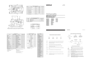
  • 1. Harness Connector Location Chart Connector Machine Location Harness And/Or Components Schematic Location A-6Y7376 Operator Monitor (EMS) E-4 A - 6Y7376 Diagnostic Connector F-7 9 Contacts A - 6Y7376 C - 7T8326 D-6 G - 9U9458 Attachment H - 9U9463 Attachment C-7 G - 9U9458 Attachment H - 9U9463 Attachment C-B G - 9U9458 Attachment Radio B-4 7Contacts A - 6Y7376 B-1011339 E-3 A - 6Y7376 B-1011339 D-3 A - 6Y7376 E - 9U9407 A-5 A - 6Y7376 Voltage Converter E-3 5 Contacts A - 6Y7376 M-6I8611 B-5 A-6Y7376 C-7T8326 D-5 A-6Y7376 G - 9U9458 Attachment D-6 A - 6Y7376 N - 9W1816 Attachment C-3 A - 6Y7376 Y - 6Y3416 Attachment C-3 Machine locations are repeated for connectors located close together. * = Connector is located at the component. A = Connector in dash area. B = Connector at relay panel. D ¹ = Connector in headliner of operators compartment. 20 Contacts 8 Contacts 6 Contacts 4 Contacts A A A A A SENR4955 February 1993 D6H Series II Tractor Electrical System 4RC5500-UP 6FC5500-UP 8FC5500-UP 1KD5500-UP 2KD5500-UP 3ED5500-UP 3ZF5500-UP 4YF5500-UP 5HF5500-UP 6CF5500-UP 6CF5500-UP 2TG5500-UP 3YG5500-UP 4GG5500-UP 4LG5500-UP 1FJ5500-UP 8ZHJ1-UP 9KJ1-UP 2DK5500-UP 5KK1-UP 6CK1-UP 7ZK1-UP 8KK1-UP 8SK1-UP 9LK1-UP 9RK1-UP 1YL1-UP 2BL1-UP 2TL1-UP Printed in U.S.A. ©1993 Caterpillar All Rights Reserved A 3 4 5 6 8 9 10 11 12 14 15 13 16 B C D 1 217 18 19 7 A 3 4 5 6 8 9 10 11 12 14 15 13 16 B C D 1 2 17 18 19 7 Machine Harness Connector And Component Locations 1 2 1 2 Component Location Component Schematic Location Machine Location Component Schematic Location Machine Location Alarm - Action (EMS) D-8 1 Sender - Hydraulic Oil Temp (Gauge) A-6 11 Alarm - Backup E-9 C Sender - Power Train Oil Temp (Gauge) B-2 12 Alternator B-1 2 Solenoid - A/C Clutch B-2 13 Batteries F-3 3 Solenoid - Start Aid F-2 14 Breaker - Alternator (60A) E-7 B Switch - Backup Alarm (CBS) D-7 C Breaker - Blower Motor F-5 B Switch - Backup Alarm (DS) E-7 C ¹ Converter - Voltage E-3 C Switch - Blower Motor (A/C) B-3 A Filter - Alternator B-5 A Switch - Blower Motor (Heater) C-3 5 Fuse - Front Dash and Dome (10A) E-7 B Switch - Disconnect F-3 3 Fuse - Key (10A) F-7 B Switch - Engine Coolant Temp (EMS) C-2 9 Fuses E-6 B Switch - Engine Coolant Temp (Start Aid) D-2 9 Gauges B-5 A Switch - Engine Oil Pressure (EMS) C-2 15 Ground - Module D-4 A Switch - Flood Lamp B-6 A Horns - Front F-1 4 Switch - Forward Horn B-6 16 Lamp - Action (EMS) D-6 A Switch - Front and Dash Lamp C-6 A Meter - Service B-5 A Switch - Fuel Press (EMS) C-2 17 Monitor - Operator (EMS) D-4 A Switch - Hydraulic Oil Temp (EMS) A-6 11 Motor - Blower (Heater) B-3 5 Switch - Key Start C-5 A Motor - Starting A-2 6 Switch - Neutral Start (DD) B-9 18 Motor - Windshield Washer A-8 7 Switch - Neutral Start (PS with DS) D-7 C ¹ Motors - Blower (A/C) B-3, C-3 8 Switch - Neutral Start (PS with CBS) D-7 C Motors - Wiper (Front & Left) C-4, E-7 D Switch - Power Train Filter Press (DS EMS) A-6 11 Motors - Wiper (Rear & Right) C-8, B-6 D Switch - Power Train Oil Temp (CBS EMS) C-2 19 Radios (12V & 24V) B-4 D ¹ Switch - Power Train Oil Temp (EMS) C-2 12 Relay - Main (Replaces Terminal Block) F-8 B Switch - Refrigerant Press F-2 13 Relay - Start F-6 B Switch - Start Aid C-6 A Resistor - Blower Motor Speed (A/C) B-3 8 Switch - Test (EMS) D-6 A Resistor - Blower Motor Speed (Heater) B-3 5 Switch - Thermostat (A/C) B-3 A Resistor - Load F-6 B Switches - Wiper B-7, B-8 D ¹ Resistor - Starter to Diagnostic Connector B-2 6 Terminal Block F-6 B Sender - Engine Coolant Temp (Gauge) C-2 9 Sender - Fuel (Gauge) D-9 10 A/C = Air Conditioning Machine locations are repeated for components located close EMS = Electronic Monitoring System (operator monitor) together. DS = Differential Steer Machines A = Components in dash area. CBS = Clutch/Brake Steer Machines B = Components at relay panel. PS = Power Shift C = Components in operator's left console. PT = Power Train C ¹ = Components within diff steer control handle of operator's left console. D = Components in operator compartment. D ¹ = Components in headliner of operators compartment. Resistor, Sender and Solenoid Specifications Part No. Component Description Resistance (Ohms)¹ 2G0413 Resistor - Blower Motor Speed 5 9G1950 Resistor - Blower Motor Speed Overall 2.0 ± .1 Tap 1.0±.05 7X6416 Resistor - Load 50 ± 5.0 6T2217 Resistor - Starter/Diagnostic Conn 150 ± 7.5 8T8813 Solenoid - A/C Clutch 14.4 ± 0.6 9G4365 Solenoid - Start Aid 6 ¹ At room temperature unless otherwise noted. Related Electrical Service Manuals Form Number Alternator (1005047): Consist No.1005046 SENR2082 Consist No.1005045 SENR4130 Electronic Monitoring System SENR2945 Starting And Charging Systems SENR2947 Starting Motor (4N3181): Consist No. 8C3651 (42-MT) SENR3581 Consist No. 9X4447 (F8) SENR4975 Consist No. 3T6305 (KE) SENR3536 Title Off Machine Switch Specification Part No. Function Actuate Deactuate Contact Position 3T5825 Power Train Oil Temperature (EMS) 129.4 ± 2.8°C (265 ± 5°F) 118.3°C MIN (245°F MIN) Normally Closed 7N9785 Engine Coolant Temperature (EMS) 107.2 ± 2.8°C (225 ± 5°F) 91.0°C MIN (196°F MIN) Normally Closed 7T0988 Engine Oil Pressure (EMS) 62 ± 21 kPa (9.0 ± 3.0 psi) 38 ± 21 kPa (5.0 ± 3.0 psi) Normally Open 8N1693 Engine Coolant Temperature (Start Aid) 37.8 ± 2.8°C (100 ± 5°F) 26.7°C MIN (80°F MIN) Normally Closed 8N2248 Hydraulic Oil Temperature (Differential Steer EMS) 101.7 ± 2.8°C (215 ± 5°F) 93.3°C MIN (200°F MIN) Normally Closed 8T8639 Refrigerant Pressure (A/C) 344.5 ± 34.5 kPa (50 ± 5 psi) 172.3 ± 21 kPa (25 ± 3 psi) Normally Open 9G1300 Hydraulic Oil Temperature (Clutch/Brake Steer EMS) 110.0 ± 2.8°C (230 ± 5.0°F) 101.7°C MIN (215°F MIN) Normally Closed 9G3341 Power Train Oil Temperature (Clutch/Brake Steer EMS) 51.7 ± 2.8°C (125 ± 5°F) 43.0°C MIN (110°F MIN) Normally Closed 9W3187 Fuel Pressure (EMS) 93 ± 21 kPa (13.5 ± 3.0 psi) 69 ± 21 kPa (10.0 ± 3.0 psi) Normally Closed 9X7781 Power Train Filter Pressure (EMS) (Differential Steer EMS) 210 ± 70 kPa (30 ± 10 psi) — — Normally Open Wire Description Wire Number Wire Color Description Power Circuits 101 RD BAT 102 BU HD LMP 105 BR KEY SW 108 BU AUX CKT 109 OR ALT OUTPUT(+) TERM. 112 PU MAIN POWER RELAY OUTPUT 113 OR OPR MON PANEL B+ SWITCHED 114 GN WARNING HORN (FORWARD) 116 BR AUX CKT 121 YL BACKUP ALARM TO LAMP 123 WH AUX CKT 124 GN A/C 129 BU AUX CKT Ground Circuits 200 BK MAIN CHASSIS 201 BK OPR MON PANEL CMS 203 BK CHASSIS DIAGNOSTIC 207 BK STARTER DIAGNOSTIC Basic Machine Circuits 301 BU STARTER NO.1 SOL 302 OR STARTER NO.1 RESISTOR TO DIAGNOSTIC 304 WH STARTER RELAY NO.1 OUTPUT 306 GN STARTER RELAY COIL TO NEUT START SW 307 OR KEY SW TO NEUT START SW 308 YL MAIN POWER RELAY COIL 310 PU START AID SW TO START AID SOL 311 WH START AID SOL TO TEMP SW 321 BR BCKP ALARM LAMP 322 GY WARNING HORN (FORWARD) Monitoring Circuits 403 GN ALTERNATOR (R) TERM. 404 YL OPR MON HYD OIL TEMP 405 GY OPR MON OIL PRESS. (LO SETTING) 406 PU OPR MON COOLANT TEMP 410 WH OPR MON ACTION ALARM 411 PK OPR MON ACTION LAMP 413 BR OPR MON FUEL PRESS. 415 GN OPR MON TEST SW 424 GY OPR MON POWER TRAIN TEMP 426 BR OPR MON POWER TRAIN OIL FILTER 441 OR ENG COOLANT TEMP GAGE 442 GY HYD SYSTEM TEMP GAGE 443 YL POWER TRAIN TEMP GAGE 447 PK FUEL LEVEL GAGE Accessory Circuits 500 BR WIPER - FRONT (PARK) 501 GN WIPER - FRONT (LO) 502 OR WIPER - FRONT (HI) 503 BR WIPER - REAR (PARK) 504 YL WIPER - REAR (LO) 505 BU WIPER - REAR (HI) 508 PU RADIO SPEAKER - LEFT 509 WH RADIO SPEAKER - LEFT (COMMON) 510 YL WASHER - PRIMER 511 BR RADIO SPEAKER - RIGHT 512 GN RADIO SPEAKER - RIGHT (COMMON) 513 OR A/C COMPRESSOR/REFRIGERANT PRESS. SW 515 GY BLOWER MOTOR (HI) 516 GN BLOWER MOTOR (MEDIUM) 517 BU BLOWER MOTOR (LO) 521 YL A/C SW TO REFRIGERANT SW 522 WH A/C CLUTCH TO THERMOSTAT SW 523 BR WIPER - LEFT (PARK) 524 BU WIPER - LEFT (LO) 525 GY WIPER- LEFT (HI) 526 YL WIPER - RIGHT (PARK) 527 GN WIPER - RIGHT (LO) 528 PK WIPER - RIGHT (HI) 592 BU DC/DC CONVERTER POWER OUTPUT A513 PK DC/DC CONVERTER MEMORY OUTPUT Lighting Circuits 600 BR DASH BASIC 608 GN FLOOD REAR 609 YL FLOOD SIDE 610 OR HEAD LAMP BASIC T Normally open switch that will close with an increase of a specific condition (temp-press-etc.). Normally open switch that is closed due to an applied condition, and will open again with a specific decrease in that condition. Normally closed switch that will open with an increase of a specific condition. Normally closed switch that is open due to an applied condition, and will close again with a specific decrease in that condition. The circle indicates that the component has screw terminals and a wire can be disconnected from it. No circle indicates that the wire cannot be disconnected from the component. This indicates that the component has a wire connected to it that is connected to ground. This indicates that the component does not have a wire connected to ground. It is grounded by being fastened to the machine. Electrical Schematic Symbols And Definitions Pressure Symbol Temperature Symbol Level Symbol Flow Symbol A AA 2 A AA 1 2 325-PK-14 C A 325-PK-14 200-BK-14 T FUSE - A component in an electrical circuit that will open the circuit if too much current flows through it. REED SWITCH - A switch whose contacts are controlled by a magnet. A magnet closes the contacts of a normally open reed switch; it opens the contacts of a normally closed reed switch. SENDER - A component that is used with a temperature or pressure gauge. The sender measures the temperature or pressure. Its resistance changes to give an indication to the gauge of the temperature or pressure. RELAY (Magnetic Switch) - A relay is an electrical component that is activated by electricity. It has a coil that makes an electromagnet when current flows through it. The electromagnet can open or close the switch part of the relay. CIRCUIT BREAKER (C/B) - A component in an electrical circuit that will open the circuit if too much current flows through it. This does not destroy the circuit breaker and it can be reset to become part of the circuit again. SOLENOID - A solenoid is an electrical component that is activated by electricity. It has a coil that makes an electromagnet when current flows through it. The electromagnet can open or close a valve or move a piece of metal that can do work. Harness And Wire Electrical Schematic Symbols SocketPin Pin or Socket Number Wire, Cable, or Harness Assembly Identification Single Wire Connector Circuit Number Identification Wire Gauge Wire Color Plug Receptacle 9X-1123 Component Part Number Electrical Schematic Symbols And Definitions 1 1 1 2 2 Typical representation of a Sure-Seal connector. The plugand receptacle contain both pins and sockets. Typical representation of a Deutsch connector. The plug contains all sockets and the receptacle contains all pins. MAGNETIC LATCH SOLENOID - A magnetic latch solenoid is an electrical component that is activated by electricity and held latch by a permanent magnet. It has two coils (latch and unlatch) that make electromagnet when current flows through them. It also has an internal switch that places the latch coil circuit open at the time the coil latches. 1 1 2 D ¹ D ¹ D ¹ * B A *
  • 2. 306-GN1 2 8 3 1 4 5 6 7 2 6 4 1 1 2 7 3 6 2 9 5 4 8 1 5 6 4 1 7 3 2 6 5 4 3 2 1 3 2 1 1 2 4 5 6 3 4 1 2 3 8 7 5 1 2 F E D 9 8 7 C B A 9 8 7 6 5 4 6 5 3 2 1 F E D 3 2 1 C B A 3 6 5 4 2 6 4 3 2 5 3 2 1 2 1 3 2 1 2 1 2 3 5 4 1 1 2 1 3 1 P 200-BK 200-BK 200-BK 108-BU-14RADIO 102-BU-14 102-BU-14 108-BU-14 STARTER RELAY 3E-0075 A 114-GN 129-BU 108-BU-14 123-WH 113-OR BK-18 207-BK 302-OR 310-PU 101-RD-6 311-WH 201-BK 203-BK 102-BU-14 112-PU-14 112-PU 308-YL 308-YL 109-OR-6 200-BK 306-GN A A AA A A A AA A A 116-BR-14 A A A A A A A A A A BK-18 109-OR-14 109-OR-8 15A 308-YL 112-PU-14 MM 200-BK LL LOAD RESISTOR 7X-6416 410-WH CIGAR LIGHTER BLOWER MOTOR BREAKER 3T-8728 20A 109-OR-6 200-BK FUSE HOLDER 4K-5122 TERMINAL BLOCK 6T-0751 ALT CIRCUIT BREAKER 9S-0173 200-BK FRONT DASH DOME FUSE 3K-8782 KEY FUSE 3K-8782 10A 10A LL 112-PU-14 200-BK 109-OR-6 A 112-PU-14 WIPER MOTORS 200-BK-14 308-YL 306-GN 200-BK-18 610-OR-18 BR ALTERNATOR FILTER 100-5052 GROUND 304-WH-8 124-GN-14 BR BK 123-WH 200-BK GR L8 442-GY 442-GY HYDRAULIC OIL TEMP GAGE 4W-0484 NOTE D M M M 123-WH-18 200-BK-18 442-GY-18 442-GY442-GY-18 442-GY 442-GY 442-GY C 442-GY GRD T SEND IGN S 442-GY 442-GY M 109-OR-6 200-BK 129-BU-14 HYDRAULIC OIL TEMP SENDER 8N-3844 515-GY-14 200-BK-14 OROPSHEATER 2 426-BR 201-BK 404-YL 4 109-OR-4 101-RD-6 201-BK 411-PK 415-GN 200-BK-14 200-BK 403-GN 405-GY 413-BR 406-PU 441-OR 201-BK 101-RD-6 404-YL 200-BK-14 426-BR 447-PK 322-GY 201-BK 200-BK 121-YL 321-BR 201-BK 522-WH-14 608-GN-14 114-GN 521-YL-14 322-GY 311-WH 521-YL-14 310-PU 610-OR-14 403-GN 522-WH-14 311-WH 310-PU 302-OR 207-BK 203-BK 124-GN-14 308-YL 105-BR 101-RD-6 109-OR-6 304-WH-8 102-BU-14 L3 L5 24V TO 12V CONVERTER NOTE G 3E-8645 A513-PK 592-BU A GROUND GROUND 200-BK 200-BK +24 V SWITCHED IN +24 V BATTERY IN 102-BU-14 108-BU-14 +12 V SWITCHED OUT 108-BU-14 102-BU-14 +12 V MEMORY OUT G 102-BU-18 200-BK-18 200-BK-18 102-BU-18 200-BK-18 2 1 3 FUSE (NOTE C) BK A 477-PK RD 200-BK-14 508-PU-18 509-WH-18 102-BU-14 RIGHT SPEAKER 6T-7695 10A 108-BU-14 109-OR-8 101-RD 200-BK 112-PU-14 116-BR-14 DIAGNOSTICCONNECTOR 60A RELAYPANEL RELAY PANEL RELAY PANEL 121-YL 105-BR 20 19 18 17 16 509-WH-18 508-PU-18 512-GN-18 511-BR-18 509-WH-18 15 14 13 9 1 200-BK 5 509-WH-18 6 508-PU-18 8 512-GN-18 12 4 304-WH 304-WH 105-BR 105-BR 101-RD-14 101-RD-14 101-RD 101-RD-6 109-OR-6 114-GN 121-YL 113-OR 123-WH 109-OR 124-GN-14 109-OR-6 306-GN FORWARD HORN BACK-UP ALARM OPERATOR MONITOR GAGES & SERVICE METER SIDE & REAR FLOOD LAMPS15A 10A 10A 15A 10A 112-PU-14 109-OR-14 112-PU-14 112-PU-14 109-OR-14 308-YL 308-YL 112-PU 207-BK 302-OR 310-PU 311-WH SIGNAL BATTERY 203-BK 7 2 10 200-BK-18 11 513-OR-14 424-GY ROOF GROUND STUD 307-OR 610-OR-14 310-PU G 522-WH-14 441-OR RD-18 3 201-BK 608-GN-14 A 306-GN 443-YL 200-BK 200-BK-14 200-BK 200-BK-8 108-BU 112-PU-14 A 200-BK MM A A A T 108-BU 108-BU 24 VOLT RADIO NOTE F LH SPEAKER (-) LH SPEAKER (+) +24 VOLT GROUND RH SPEAKER (-) RH SPEAKER (+) ANTENNA WH/BK, GN/BK-18 WH/GN-18 G BK-18 GY/BK, PU/BK-18 GY/PU-18 G 511-BR-18 512-GN-18 200-BK-18 592-BU-18 A513-PK-18 508-PU-18 509-WH-18 509-WH-18 508-PU-18 A513-PK-18 592-BU-18 608-GN-14 200-BK-14 129-BU-14 200-BK-14 A513-PK-18 592-BU-18 200-BK-18 509-WH-18 508-PU-18 108-BU 523-BR-18 524-BU-18 525-GY-18 500-BR-18 501-GN-18 502-OR-18 108-BU ANTENNA 9W-3072 108-BU 200-BK-18 525-GY-18 524-BU-18 523-BR-18108-BU 108-BU 108-BU 108-BU 108-BU V 3T-1480 C-1 PK BK 03 C-36Y-3416Y 01 00 1 3 2 200-BK-14 W 6Y-1200 B-8 BLOWER SW 1V-6652 4 200-BK-18 Y 512-GN-18 124-GN-14 Y 12 VOLT RADIO NOTE F 200-BK-14 517-BU-14 515-GY-14 1 B-3 X 1 2 X 124-GN-14 200-BK M 123-WH-18 447-PK-18 441-OR-18 200-BK-14 L2 OROPSHEATER 426-BR 200-BK-18 116-BR-14 610-OR-14 SERVICE METER 3E-9358 200-BK-18 501-GN-18 500-BR-18 502-OR-18 512-GN-18 511-BR-18 508-PU-18 511-BR-18 512-GN-18 W L2 508-PU-18 502-OR-18 200-BK 200-BK WH L2 200-BK-14 U 306-GN 200-BR-14 121-YL L7 108-BU 500-BR-18 501-GN-18 102-BU-14 201-BK 200-BK 201-BK 201-BK 201-BK 201-BK 201-BK 201-BK 201-BK 201-BK 200-BK 201-BK 447-PK L13 426-BR 426-BR 200-BK-14 610-OR-14 200-BK-14 200-BK-14 200-BK-14 200-BK-14 322-GY-14 200-BK-14 200-BK D D L13 517-BU-14 RESISTOR 2G-0413 515-GY-14 515-GY-14 X 1 2 X MOTOR BK-14 WH/RD-14 BLOWER 7X-6279 517-BU-14 516-GN-14 515-GY-14 515-GY-14 FUEL SENDER 3E-6261 441-OR 200-BK-14 200-BK-14 P F 201-BK 201-BK 201-BK V B 2 1 109-OR-4 RD-00 BK-00 FF FF A 200-BK-8 509-WH-18 307-OR 306-GN C C C C L7 L8 L7 L13 C C C CC C C C C C CC G EEE E C L8 M M M Q Q Q M M XX XX D 2 1 2 D XX XX L4 B B B B XX XX L4 200-BK-14 D-78E-1538 02 019W-5275 D-7 E L NEUTRAL START SW 9N-1750 NOTE D 321-BR BACKUP ALARM SW 9N-1750 NOTE D A UU 200-BK 321-BR NEUTRAL START SW (POWER SHIFT WITH CLUTCH/BRAKE STEER) 9W-1581 UU UU 200-BK-18 200-BK-18 200-BK-18 200-BK-18 RR G L H LEFT SPEAKER 6T-7695 A A 403-GN 608-GN-14 200-BK-14 Z Z H H 01 03 H NOTE F: 24 TO 12 VOLT CONVERTER NOT REQUIRED WITH 02 A H 00 00 6Y-7376 403-GN 00 00 01 02 03 00 00 01 02 02 00 04 00 H 01 01 F-6 02 01 01 H A-33T-2980FF 3T-8636 9U-9463 9U-9458 6I-8609 7P-6682 3P-2182 8S-1078 9G-8921 6Y-1201 CABLE AS. ATCH WIRE, CABLE, COMPONENT B-5Q 8E-0937 CHG MM LL 8E-0936 COMPONENTS ARE SHOWN INSTALLED ON A FULLY OPERABLE MACHINE WITH THE KEY AND ENGINE OFF, AND XMSN SHIFTER IN NEUTRAL A-2EE F-3DD F-3CC F-39V-2098BB F-3AA E-99G-6259KK A-23N-0539JJ B-14D-6565 A-49U-8746NN WIRE AS. C-98E-1117S C-26T-2934P C-39W-1816N B-56I-8611M A-8L B-9J B-7H B-7G C-23T-8624F A-59U-9407E E-15G-9496D D-6C D-3101-1339B LOC HARNESS AS. HH CIRCUIT NOT CONNECTED CIRCUIT CONNECTED 1 2 A P 01 H H L 511-BR-18 200-BK-18 108-BU 306-GN X H H H 102-BU-18 NOTE C: FUSES 10A - 3K8782; 15A - 8M8948 NOTE B: NORMALLY OPEN BEFORE INSTALLATION NOTE A: NORMALLY OPEN BEFORE REFRIGERANT CHARGE H H H BLADE, SPADE, RING, OR SCREW TERMINAL INTERNAL ELECTRICAL CONNECTION TO SURFACE OF COMPONENT ELECTRICAL CONNECTION TO VEHICLE STRUCTURE CONNECTOR SYMBOL DESCRIPTION HH H H UNLESS OTHERWISE SPECIFIED: ALL WIRE IS 16 GAGE PART NO.IDENT THIS SCHEMATIC IS FOR THE D6H TTT (6T-3295 CHG 06) MAIN RELAY 3T-0376 (REPLACES TERMINAL BLOCK AT F-6 WHEN LOAD CURRENT EXCEEDS 10 AMPS) BK/PK-14 BK-14 FLOOD LAMP 9X-6775 H L ATCH ATCH ATCH ATCH - + + - 8 7 ATCH RR 608-GN-14 200-BK-14 121-YL 321-BR BASE 3T0304 A 112-PU-14 112-PU-14 308-YL ATCH C LEFT WIPER 7X-6112 ACTION ALARM 9G-9813 BACKUP ALARM 3T-1815 200-BK C A A KK S C A AG G A A 592-BU-18 310-PU 308-YL 307-OR 105-BR 608-GN-14 610-OR-14 116-BR-14 102-BU-14 L5 201-BK 411-PK 415-GN 608-GN-14 609-YL-14 CIGAR LIGHTER 9W-0335 200-BK OPERATOR MONITOR TEST SW 7N-8001 ACTION LAMP 7N-1996 201-BK 415-GN 201-BK 411-PK 200-BK-14 KEY START SW 9G-7641 START AID SW 3T-3453 OPERATOR STATION OPERATORSTATION 102-BU-14 BK-12 E RD BK2 1 201-BK 410-WH 200-BK-18 310-PU 308-YL 308-YL 307-OR 105-BR ON OFF B S C R BK-12 NN 201-BK 410-WH 108-BU-14 Q C C 592-BU-18 A513-PK-18 A513-PK-18 2 1 108-BU-14 116-BR-14 200-BK-18 304-WH-8 109-OR-6 101-RD-6 123-WH-18 610-OR-18 610-OR-18 610-OR-18 610-OR-18 LAMP 5D-0019 123-WH-18 123-WH-18 NN DD CC BB 521-YL-14 513-OR-14 322-GY 200-BK-14 610-OR-14 D D 114-GN 121-YL 113-OR 123-WH F F V V B B GN GN HH B AA A A BLUE GREEN BU RR 2 1 GN RD WH OR YL PK BK 410-WH 307-OR 306-GN A JJ 201-BK ATCH 306-GN 307-OR A UU DIFFSTEERTILLER 307-OR BROWN PURPLE GRAY BLACK COLOR 105-BR 306-GN 308-YL 124-GN-14 203-BK 207-BK 302-OR 310-PU 311-WH 200-BK ABBREV PINK 200-BK 200-BK 200-BK 321-BR 306-GN 321-BR YELLOW 108-BU-14 102-BU-14 200-BK 308-YL 308-YL-14 200-BK 109-OR-4 112-PU-14 112-PU-14 8 608-GN-14 H 7 H A 129-BU-14 447-PK 523-BR-18 524-BU-18 525-GY-18 108-BU DOME LAMP 8C-9678 GN GY BR OR 4 2 3 1 H L OPERATORSTATION 200-BK-14 ENGINE OIL SW 7T-0988 B B 443-YL 513-OR-14 200-BK-14 322-GY-14 HEAD LAMP 9X-6874 12V BATTERY 3T-5760 STD 9G-4247 ATCH 12V BATTERY 3T-5760 STD 9G-4247 ATCH BK-18 BK-18 START AID SOLENOID 9G-4365 B MODULE GROUND 521-YL-14 FRAME 03 P 00 200-BK DISCONNECT SW 7N-0718 FRONT HORN 7T-0969 FRONT HORN 7T-0970 OPERATOR MONITOR 3T-9100 200-BK BA DD CCBBAA D B A B BA 200-BK-14 200-BK-14 200-BK-14 101-RD-6 E E 201-BK 109-OR-4 201-BK 522-WH-14 5 6 3 4 2 1 207-BK 302-OR 610-OR-14 201-BK 322-GY 405-GY OPERATOR STATION 102-BU-14 610-OR-14 201-BK STARTING AID TEMP SW 8N-1693 200-BK 310-PU 311-WH 404-YL 321-BR 121-YL 114-GN 608-GN-14 201-BK 426-BR 404-YL 447-PK 200-BK-14 201-BK 200-BK-8 123-WH 513-OR-14 413-BR 322-GY 322-GY 201-BK RD-00 443-YL 447-PK 441-OR G 200-BK 200-BK 441-OR 406-PU 413-BR 405-GY 403-GN 403-GN PWR TN FLTR 426-BR 447-PK 101-RD-6 304-WH-8 109-OR-6 200-BK-8 302-OR 207-BK 304-WH-8 200-BK-8 MOTOR 522-WH-14 114-GN 121-YL 321-BR 201-BK 410-WH 123-WH 116-BR-14 200-BK-14 108-BU-14 113-OR 108-BU-14 116-BR-14 105-BR 308-YL 310-PU 608-GN-14 BK-00 BK-00 203-BK T L1 513-OR-14 610-OR-14 T L4 403-GN 441-OR 413-BR 201-BK L1 406-PU 311-WH 311-WH L1 L3 M 200-BK-14 1 2 311-WH 310-PU 610-OR-14 322-GY 1 REFRIGERANT SW 8T-8639 NOTE A 201-BK 200-BK-14 BK COOLANT TEMP SW 7N9785 ORANGE WHITE 1 2 3 610-OR-14 M 200-BK-14 N N N N 200-BK T PWR TN TEMP 113-OR A 424-GY 415-GN 411-PK 404-YL 403-GN 413-BR 405-GY 424-GY 406-PU 201-BK 201-BK 201-BK 201-BK 201-BK 201-BK 410-WH COOL TEMP + BATTERY GROUND ALTERNATOR HYD TEMP ENG OIL PR ALARM LAMP FUEL PR TEST 11 20 19 18 17 16 15 14 13 12 10 9 8 7 6 5 4 3 2 1 RD-00 NEGPOSNEGPOS BK-00 WASHER 7T-8891 FLOOD LAMP 9X-6775 510-YL-18 510-YL-18510-YL-18510-YL-18 RED FLOOD LAMP SW 3T-1730 609-YL-14 POWERTRAIN FILTER SW 9X-7781 NOTE B 600-BR 5 4 2 1 RIGHT WIPER 7X-1751 A513-PK E-4 610-OR-18 02 H HH G G G E A 510-YL-14 610-OR-14 102-BU-14 102-BU-14 3 610-OR-18 00 UU NOTE UU UU 200-BK-14 T BK-12 608-GN-14 FRONT & DASH LAMP SW 7T-3946 610-OR 116-BR-14 116-BR-14 608-GN-14 443-YL H HYDRAULIC OIL TEMP SW 9G-1300 NOTE E 8N-2248 NOTE D 447-PK 306-GN 129-BU-14 129-BU-14 129-BU-14 200-BK-14200-BK-14 129-BU-14 200-BK-14 426-BR 201-BK 404-YL GY/PU-18 GY/BK, PU/BK-18 BK-18 RD-18 YL-18 WH/GN-18 WH/BK, GN/BK-18 ANTENNA RH SPEAKER (+) RH SPEAKER (-) GROUND +12 VOLT +12 VOLT MEMORY LH SPEAKER (+) LH SPEAKER (-) 592-BU BR 610-OR-14 608-GN-14 609-YL-14 592-BU A513-PK 200-BK-18 200-BK-18 108-BU 526-YL-18 527-GN-18 528-PK-18 528-PK-18 527-GN-18 526-YL-18 108-BU 509-WH-18 508-PU-18 REAR WIPER 9X-3392 108-BU 505-BU-18 504-YL-18 503-BR-18 510-YL-18 108-BU 511-BR-18 512-GN-18 PU GN GY BR OR 4 2 3 1 H L BK-12 108-BU 108-BU 502-OR-18 501-GN-18 500-BR-18 525-GY-18 524-BU-18 523-BR-18 MOTOR 510-YL-18 108-BU 528-PK-18 527-GN-18 526-YL-18 T 108-BU-18 505-BU-18 504-YL-18 503-BR-18 108-BU 108-BU REAR WIPER SW 3T-6655 RIGHT WIPER SW 3T-6655 LEFT WIPER SW 3T-6655 FRONT WIPER SW 3T-6655 B W P L H B B W L H B B W P L H B B W P L H B 526-YL-18 527-GN-18 528-PK-18 108-BU T 24 VOLT RADIO RADIO OPTIONS 12 VOLT RADIOS 3E-7140 FIXED U.S. 3E-7141 REMOVEABLE U.S. 3E-6107 FIXED EUROPE 3E-6106 REMOVEABLE EUROPE MOTOR L H 1 3 2 4 OR BR GY GN T H OPERATOR STATION 510-YL-14 200-BK-14 510-YL-18 MOTOR H LAMP 5D-0019 LAMP 5D-0019 LAMP 5D-0019 BK-6 HEAD LAMP 9X-6874 FF STARTER 4N-3181 STD 3T-8946 ATCH AUX START RECEPTACLE C 610-OR-18 610-OR-18610-OR-18 C Q 3 GN GY BR OR OPERATOR MONITOR PANEL MOUNTING BOLT 521-YL-14 200-BK-14 IGN SEND GRD IGN SEND GRD IGN SEND GRD 515-GY-14 516-GN-14 200-BK-14 RESISTOR 9G-1950 THERMOSTAT SW 3E-5465 124-GN-14 521-YL-14 T BLOWER SW 6P-3236 H 4 424-GY RD-00 BK-00 POWERTRAIN OIL TEMP SENDER 8N-3844 2 1 COOLANT TEMP GAGE 4W-0483 POWERTRAIN OIL TEMP GAGE 4W-0485 600-BR600-BR 1 2 FUEL LEVEL GAGE 9X-3496 FRONT WIPER 9X-3392 RESISTOR 6T-2217 POWERTRAIN OIL TEMP SW 3T-5825 ALTERNATOR 100-5047 502-OR-18 108-BU 500-BR-18 501-GN-18 BASE 7G-9730 BASE 7G-9730 FUEL PRESS SW 9W-3187 7X-2041 N N JJEE G FN M A A A F-6 HH A 4 OROPS HEATER 3 522-WH-14 4 201-BK 2 1 1 3 2 322-GY 114-GN 403-GN OPERATORSTATION 200-BK200-BK POWERTRAIN OIL TEMP SW 9G-3341 NOTE E 426-BR 201-BK 2 PANEL LAMP 7N-9967 PANEL LAMP 7N-9967 600-BR NOTE E: FOR CLUTCH/BRAKE STEER ONLY RR 403-GN NOTE D: FOR DIFF STEER ONLY 200-BK 511-BR-18 GR BK T 201-BK 424-GY 3 1 H T 443-YL 424-GY 201-BK T L MOTOR T 5 200-BK-14 124-GN-14 2 3 1 BLOWER 9G-8697 2RED BLK BLU GRN OR 517-BU-14 200-BK-14 BLOWER 9G-8693 2 2 1 1WH/RD-14WH/RD-14 BK-14BK-14 MOTOR MOTOR FORWARD HORN SW 3T-2357 304-WH-8 301-BU 304-WH-8 302-OR 207-BK 200-BK-8 FRAME ENG BLK 322-GY 114-GN 201-BK 426-BR 404-YL 121-YL 321-BR 608-GN-14 200-BK-14 AIR CONDITIONER CLUTCH SOLENOID 8T-8813 BK-6 207-BK BK-00 RD-00 G S MTR BAT MOTOR 123-WH-18 200-BK-18 123-WH-18 COOLANT TEMP SENDER 6N-5926 406-PU T 443-YL-18 441-OR-18 447-PK-18 123-WH-18 123-WH 200-BK-18 447-PK 441-OR 443-YL L4 7T-8326 GY BK 200-BK-18 200-BK-18200-BK-18 123-WH-18 OPERATOR STATION RD-00 413-BR 610-OR-14 ALT +R 24 VOLT RADIOS 9X-6779 FIXED U.S. 9X-6778 REMOVEABLE U.S. 3E-7890 FIXED EUROPE 9X-5288 REMOVEABLE EUROPE B 102-BU-14 105-BR 308-YL 124-GN-14 310-PU 311-WH 1 M T 306-GN 410-WH 307-OR 201-BK ST BACKUP ALARM SW 7T-8744 NOTE E W G 1 2 WIRES THAT HAVE BATTERY VOLTAGE WHEN THE KEY SWITCH IS OFF. WIRES THAT HAVE BATTERY VOLTAGE WHEN THE KEY SWITCH IS ON. STARTING CIRCUIT GAUGE CIRCUIT. EMS CIRCUIT. PANEL LAMP CIRCUIT. WIPER/WASHER CIRCUIT. HEATER AND AIR CONDITIONER CIRCUIT GROUND CIRCUIT START AID CIRCUIT ALL DASHED LINES ARE ATTACHMENTS 4 2 00T 8E-1684 C-9/E-9 D-900U ATCH 9U-9456 D 01 B-1/F-18E-2137XX ATCH 03 F-33P-2179BB ATCH 306-GN 307-OR 307-OR 2 1BK BK B 129-BU-14 307-OR 307-OR 306-GN 200-BK 200-BK 321-BR 307-OR 306-GN 307-OR 201-BK 201-BK 306-GN 321-BR 321-BR 200-BK 200-BK NOTE: FOR DIFF STEER PLUG HARNESS AS. “A” INTO HARNESS AS. “UU”; FOR POWERSHIFT WITH CLUTCH/BRAKE STEER PLUG HARNESS AS. “A” INTO HARNESS AS. “RR”; FOR DIRECT DRIVE LEAVE HARNESS AS. “A” OPEN. 2 1 1 2 A 200-BK 321-BR BK/PK BK/PK 1 2 200-BK-14 608-GN-14 U A 447-PK 200-BK-14 447-PK 447-PK 200-BK-14 608-GN-14 2 1 200-BK-14 608-GN-14 200-BK-14 608-GN-14 2 1 J A 307-OR 306-GN 307-OR 306-GN 2 1 J A 306-GN 306-GN NOTE: PLUG WIRE ASSEMBLY “J” INTO HARNESS “A” FOR DIRECT DRIVE; LEAVE HARNESS “A” OPEN FOR POWER SHIFT. NEUTRAL START SW DIRECT DRIVE ONLY 9P-9520 JJ S T 200-BK 321-BR 307-OR 306-GN L7 ATCH STD