Data sheet W3G910LV1236-EBMPAPST
•
0 recomendaciones•81 vistas

Data sheet W3G910LV1236-EBMPAPST Liên hệ: 0849 684 333 ============================= ebm papst w2s130 aa03 01 w2e200 hk38 01 w2e142 bb01 01 quạt ebm papst 4656n ebm papst 4650n w2e250 hl06 01 r2e190 ra26 05 w2e143 ab09 01 4656n w2s130 bm03

Recomendados
Más contenido relacionado
Similar a Data sheet W3G910LV1236-EBMPAPST
Similar a Data sheet W3G910LV1236-EBMPAPST (20)
Más de PHỤ TÙNG CÔNG NGHIỆP
Más de PHỤ TÙNG CÔNG NGHIỆP (20)
Último
Último (20)
Data sheet W3G910LV1236-EBMPAPST
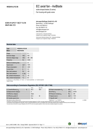
- 1. EC axial fan - AxiBlade sickle-shaped blades (S series) Fan housing with guide vanes W3G910-LV12-36 ebm-papst Mulfingen GmbH & Co. KG Bachmühle 2 · D-74673 Mulfingen Phone +49 7938 81-0 Fax +49 7938 81-110 info1@de.ebmpapst.com www.ebmpapst.com Limited partnership · Headquarters Mulfingen Amtsgericht (court of registration) Stuttgart · HRA 590344 General partner Elektrobau Mulfingen GmbH · Headquarters Mulfingen Amtsgericht (court of registration) Stuttgart · HRB 590142 Nominal data Type W3G910-LV12-36 Motor M3G150-NA Phase 3~ Nominal voltage VAC 400 Nominal voltage range VAC 380 .. 480 Frequency Hz 50/60 Method of obtaining data ml Speed (rpm) min-1 1070 Power consumption W 3250 Current draw A 5.0 Max. back pressure Pa 300 Max. back pressure in. wg 1.2 Min. ambient temperature °C -40 Max. ambient temperature °C 60 ml = Max. load · me = Max. efficiency · fa = Free air · cs = Customer specification · ce = Customer equipment Subject to change Data according to Commission Regulation (EU) 327/2011 (EN 17166) Actual Req. 2015 01 Overall efficiency ηes % 59.3 36.8 02 Measurement category A 03 Efficiency category Static 04 Efficiency grade N 62.5 40 05 Variable speed drive Yes Data obtained at optimum efficiency level. The efficiency values displayed for achieving conformity with the Ecodesign Regulation EU 327/2011 has been reached with defined air duct components (e.g. inlet rings). The dimensions must be requested from ebm-papst. If other air conduction geometries are used on the installation side, the ebm-papst evaluation loses its validity/the conformity must be confirmed again. The product does not fall within the scope of Regulation (EU) 2019/1781 due to the exception specified in Article 2 (2a) (motors completely integrated into a product). 09 Power consumption Ped kW 3.12 09 Air flow qv m³/h 24750 09 Pressure increase pfs Pa 256 10 Speed (rpm) n min-1 1070 11 Specific ratio* 1.00 * Specific ratio = 1 + pfs / 100 000 Pa LU-190226 Item no. 56913-5-9980 · ENU · Change 230625 · Approved 2022-01-18 · Page 1 / 7 ebm-papst Mulfingen GmbH & Co. KG · Bachmühle 2 · D-74673 Mulfingen · Phone +49 (0) 7938 81-0 · Fax +49 (0) 7938 81-110 · info1@de.ebmpapst.com · www.ebmpapst.com EBM PAPST VIỆT NAM 0849 684 333
- 2. EC axial fan - AxiBlade sickle-shaped blades (S series) Fan housing with guide vanes W3G910-LV12-36 Technical description Weight 55.6 kg Size 910 mm Motor size 150 Rotor surface Painted black Electronics housing material Die-cast aluminum, painted gray Impeller material PP plastic Fan housing material Sheet steel, galvanized and coated with black plastic (RAL 9005) Material guide vanes PP plastic Guard grille material Steel, coated with black plastic (RAL 9005) Internal diffuser material including cover PP plastic Number of blades 5 Blade pitch 0° Airflow direction V Direction of rotation Clockwise, viewed toward rotor Degree of protection IP55 Insulation class "F" Moisture (F) / Environmental (H) protection class H2+C Ambient temperature note Occasional start-up at temperatures between -40°C and -25°C is permitted. For continuous operation at ambient temperatures below -25°C (such as refrigeration applications), use must be made of a fan design with special low-temperature bearings. Max. permitted ambient temp. for motor (transport/storage) +80 °C Min. permitted ambient temp. for motor (transport/storage) -40 °C Installation position Shaft horizontal or rotor on bottom; rotor on top on request Condensation drainage holes On rotor side Mode S1 Motor bearing Ball bearing Technical features - Operation and alarm display with LED - External 15-50 VDC input (parameterization) - Alarm relay - Integrated PI controller - Configurable inputs/outputs (I/O) - MODBUS V6.3 - Motor current limitation - RS-485 MODBUS-RTU - Soft start - Voltage output 3.3-24 VDC, Pmax = 800 mW - Control interface with SELV potential safely disconnected from the mains - Thermal overload protection for electronics/motor - Line undervoltage / phase failure detection EMC immunity to interference According to EN 61000-6-2 (industrial environment) EMC interference emission According to EN 61000-6-3 (household environment), except EN 61000-3-2 for professionally used equipment with a total rated power greater than 1 kW Touch current according to IEC 60990 (measuring circuit Fig. 4, TN system) <= 3.5 mA Item no. 56913-5-9980 · ENU · Change 230625 · Approved 2022-01-18 · Page 2 / 7 ebm-papst Mulfingen GmbH & Co. KG · Bachmühle 2 · D-74673 Mulfingen · Phone +49 (0) 7938 81-0 · Fax +49 (0) 7938 81-110 · info1@de.ebmpapst.com · www.ebmpapst.com
- 3. EC axial fan - AxiBlade sickle-shaped blades (S series) Fan housing with guide vanes W3G910-LV12-36 Electrical hookup Terminal box Motor protection Reverse polarity and locked-rotor protection Protection class assignment I; If a protective earth is connected by the customer This component for installation may have several local protection classes. This information relates to this component’s basic design. The final protection class is based on the component’s intended installation and connection. Conformity with standards EN 61800-5-1; CE Approval UL 1004-7 + 60730-1; CSA C22.2 No. 77 + CAN/CSA-E60730-1; EAC Item no. 56913-5-9980 · ENU · Change 230625 · Approved 2022-01-18 · Page 3 / 7 ebm-papst Mulfingen GmbH & Co. KG · Bachmühle 2 · D-74673 Mulfingen · Phone +49 (0) 7938 81-0 · Fax +49 (0) 7938 81-110 · info1@de.ebmpapst.com · www.ebmpapst.com
- 4. EC axial fan - AxiBlade sickle-shaped blades (S series) Fan housing with guide vanes W3G910-LV12-36 Product drawing 1 Airflow direction "V" 2 Cable diameter min. 4 mm, max. 10 mm, tightening torque 4 ± 0.6 Nm (The tightening torque is designed for PVC cables. If the cable materials are different, the tightening torque may have to be adjusted) 3 Tightening torque 1.5 ± 0.2 Nm 4 Tightening torque 3 ± 0.3 Nm 5 Attachment holes for FlowGrid (91000-2-2957 not included in scope of delivery) Item no. 56913-5-9980 · ENU · Change 230625 · Approved 2022-01-18 · Page 4 / 7 ebm-papst Mulfingen GmbH & Co. KG · Bachmühle 2 · D-74673 Mulfingen · Phone +49 (0) 7938 81-0 · Fax +49 (0) 7938 81-110 · info1@de.ebmpapst.com · www.ebmpapst.com
- 5. EC axial fan - AxiBlade sickle-shaped blades (S series) Fan housing with guide vanes W3G910-LV12-36 Connection diagram No. Conn. Designation Function/assignment CON1 L1, L2, L3 Power supply, phase, see nameplate for voltage range PE PE Protective earth CON2 RSA RS485 interface for MODBUS, RSA; SELV CON2 RSB RS485 interface for MODBUS, RSB; SELV CON2 GND Reference ground for control interface, SELV CON2 IO1 Function parameterizable (see “Optional interface functions” table) Factory setting: Digital input - high active, function: Disable input, SELV - inactive: Pin open or applied voltage < 1.5 VDC - active: applied voltage 3.5-50 VDC Reset function: Triggering of error reset on change of state from "enabled" to "disabled" CON2 IO2 Function parameterizable (see “Optional interface functions” table) Factory setting: Analog input 0-10 V / PWM, Ri=100 kΩ, function: Set value Characteristic curve parameterizable (see input characteristic curve P1-IN), SELV CON2 IO3 Function parameterizable (see “Optional interface functions” table) Factory setting: Analog output 0-10 V, max. 5 mA, function: Fan modulation level Characteristic curve parameterizable (see output characteristic curve P3-OUT), SELV CON2 Vout Voltage output 3.3-24 VDC ±5%, Pmax=800 mW, voltage parameterizable Factory setting: 10 VDC short-circuit-proof, supply for external devices, SELV alternatively: 15-50 VDC input for parameterization via MODBUS without line voltage CON2 COM Status relay, floating status contact, common connection, contact rating 250 VAC / 2 A (AC1) / min. 10 mA, reinforced insulation on supply side and on control interface side CON2 NC Status relay, floating status contact, break for failure LED green: status = good, ready for operation orange: status = warning red: status = failure P1-IN Input characteristic curve P3-OUT Output characteristic curve Item no. 56913-5-9980 · ENU · Change 230625 · Approved 2022-01-18 · Page 5 / 7 ebm-papst Mulfingen GmbH & Co. KG · Bachmühle 2 · D-74673 Mulfingen · Phone +49 (0) 7938 81-0 · Fax +49 (0) 7938 81-110 · info1@de.ebmpapst.com · www.ebmpapst.com
- 6. EC axial fan - AxiBlade sickle-shaped blades (S series) Fan housing with guide vanes W3G910-LV12-36 Terminal/plug assignment For further information and additional functions see EC Control Software, Fan-Set-App, or MODBUS Parameter Specification V6.3 D101 [...] D147 [...] D104 [...] D12E [...] D148 [...] D16C [...] D16A [...] (selected directly via IO mode) (selected directly via IO mode) D130 [0] D130 [1] D130 [2] D130 [5] D00C [1] D130 [4] switch: direction of rotation: cw / ccw source: set value source: sensor value switch: parameter set: #1 / #2 switch: control function: heating (pos.) / cooling (neg.) signal: system modulation level % signal: remote control output 0-10V pulse input for auto-adressing pulse output for auto-adressing switch: set value source switch: fan enable / disable signal: tach out signal: diagnostics out signal: fan modulation level % signal: actual speed configurable IO functions: normal / inverse switch: direction of rotation: cw / ccw source: set value source: sensor value switch: parameter set: #1 / #2 switch: control function: heating (pos.) / cooling (neg.) signal: system modulation level % signal: remote control output 0-10V pulse input for auto-adressing pulse output for auto-adressing switch: set value source switch: fan enable / disable signal: tach out signal: diagnostics out signal: fan modulation level % signal: actual speed CON2 configurable IO mode electrical specification MODBUS Register for IO mode configuration Din1 (active high): digital input not active: pin open or applied voltage < 1,5VDC active: applied voltage 3,5-50VDC, SELV D158 [0] ○ ○ ○ ○ ○ ○ ○ Ain1 0-10V/PWM: analog input Ri = 100K, characteristic curve parameterizable, f PWM = 1k..10KHz, SELV D158 [2] ○ ○ ○ Tach out (open collector output) Umax = 50VDC, Imax = 20mA, SELV D158 [5] ○ ○ Diagnostics out (open collector output) Umax = 50VDC, Imax = 20mA, SELV D158 [6] ○ ○ Din2 (active high): digital input not active: pin open or applied voltage < 1,5VDC active: applied voltage 3,5-50VDC, SELV D159 [0] ○ ○ ○ ○ ○ Ain2 0-10V/PWM: analog input D159 [2] Ri = 100K, characteristic curve parameterizable, f PWM = 1k..10KHz, SELV ○ Ain2 4-20mA: analog input Ri = 125R, characteristic curve parameterizable, SELV D159 [3] ○ Din3 (active high): digital input not active: pin open or applied voltage < 1,5VDC active: applied voltage 3,5-50VDC, SELV D15A [0] ○ Din3 (active low): digital input not active: pin open or applied voltage 3,5-50VDC active: applied voltage < 1,5VDC, SELV D15A [1] ○ PWMin3: digital input, idle level high PWM = 40Hz - 10kHz, characteristics parameterizable active: pin open or applied voltage 3,5-50VDC not active: applied voltage < 1,5VDC, SELV D15A [7] ○ Aout3 0-10V: analog output function parameterizable, max. 5mA, max output frequency 300Hz, SELV D15A [4] ○ ○ ○ ○ ○ ○ Tacho out (pulses), analog output 0-10V max. 5mA, max output frequency 300Hz, SELV D15A [5] ○ ○ Diagnostics out (pulses) 0-10V max. 5mA, max output frequency 300Hz, SELV D15A [6] ○ RSA RSB RS485 bus connection, MODBUS RTU, specification V6.3, SELV ○ ○ ○ ○ ○ ○ Vout voltage output voltage parameterizable 3,3...24VDC +/- 5%, Pmax=800mW, short-circuit-proof, supply for external devices, SELV 15...50VDC switch: direction of rotation: cw / ccw source: set value source: sensor value switch: parameter set: #1 / #2 switch: control function: heating (pos.) / cooling (neg.) signal: system modulation level % signal: remote control output 0-10V pulse input for auto-adressing pulse output for auto-adressing IO1 IO2 ○ ○ switch: set value source switch: fan enable / disable signal: tach out signal: diagnostics out signal: fan modulation level % signal: actual speed IO3 ○ ○ ○ ○ ○ ○ configurable option INPUT OUTPUT alternatively: Input auxillary power supply for parameterization via RS485/MODBUS RTU without line voltage D16E [...] ○ PWMin3: digital input, idle level low 40Hz - 10kHz, characteristics parameterizable active: applied voltage 3,5-50VDC not active: pin open or applied voltage < 1,5VDC, SELV D15A [8] ○ Item no. 56913-5-9980 · ENU · Change 230625 · Approved 2022-01-18 · Page 6 / 7 ebm-papst Mulfingen GmbH & Co. KG · Bachmühle 2 · D-74673 Mulfingen · Phone +49 (0) 7938 81-0 · Fax +49 (0) 7938 81-110 · info1@de.ebmpapst.com · www.ebmpapst.com
- 7. EC axial fan - AxiBlade sickle-shaped blades (S series) Fan housing with guide vanes W3G910-LV12-36 Curves: Air performance 50 Hz qv m³/h cfm p fs Pa in. wg 5000 10000 15000 20000 25000 30000 35000 0 4000 8000 12000 16000 20000 50 100 150 200 250 300 0.2 0.4 0.6 0.8 1 1.2 1 2 3 4 5 6 7 8 9 10 11 12 13 14 15 16 ρ = 1.15 kg/m³ ± 2 % Measurement: LU-190226-1 Air performance measured according to ISO 5801 installation category A. For detailed information on the measurement setup, contact ebm-papst. Intake sound level: Sound power level according to ISO 13347 / sound pressure level measured at 1 m distance from fan axis. The values given are valid under the specified measuring conditions and may vary due to conditions of installation. For deviations from the standard configuration, the parameters have to be checked on the installed unit. Measured values 1 2 3 4 5 6 7 8 9 10 11 12 13 14 15 16 Wired 3~ 3~ 3~ 3~ 3~ 3~ 3~ 3~ 3~ 3~ 3~ 3~ 3~ 3~ 3~ 3~ U V 400 400 400 400 400 400 400 400 400 400 400 400 400 400 400 400 f Hz 50 50 50 50 50 50 50 50 50 50 50 50 50 50 50 50 n min-1 1070 1070 1070 1070 900 900 900 900 700 700 700 700 500 500 500 500 Ped W 2143 2624 2945 3250 1254 1511 1745 1925 590 711 821 906 215 259 299 330 I A 3.34 4.05 4.52 5.00 1.95 2.33 2.68 2.95 0.92 1.10 1.26 1.39 0.34 0.40 0.46 0.51 LpAin dB(A) 74 72 74 84 70 67 70 79 63 61 63 73 55 52 55 64 LwAin dB(A) 82 81 82 91 77 76 78 87 71 70 72 80 62 61 63 72 LwAout dB(A) 83 81 82 92 79 77 78 87 72 70 71 81 64 62 63 72 qV m3/h 35825 32205 27610 21835 29965 26880 23190 18310 23305 20905 18035 14240 16645 14935 12885 10170 pfs Pa 0 100 200 300 0 70 141 211 0 42 85 128 0 22 44 65 qV cfm 21085 18955 16250 12855 17635 15820 13650 10775 13715 12305 10615 8380 9795 8790 7585 5985 pfs in. wg 0.00 0.40 0.80 1.20 0.00 0.28 0.57 0.85 0.00 0.17 0.34 0.51 0.00 0.09 0.18 0.26 Wired = Wiring · U = Voltage · f = Frequency · n = Speed (rpm) · Ped = Power consumption · I = Current draw · LpAin = Sound pressure level intake side · LwAin = Sound power level intake side LwAout = Sound power level outlet side · qV = Air flow · pfs = Pressure increase Item no. 56913-5-9980 · ENU · Change 230625 · Approved 2022-01-18 · Page 7 / 7 ebm-papst Mulfingen GmbH & Co. KG · Bachmühle 2 · D-74673 Mulfingen · Phone +49 (0) 7938 81-0 · Fax +49 (0) 7938 81-110 · info1@de.ebmpapst.com · www.ebmpapst.com