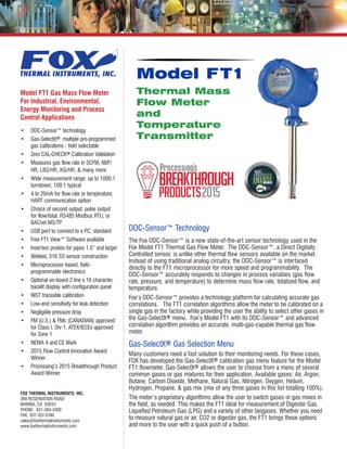
Thermal Mass Flowmeter and Temperature Transmitter
•
2 recomendaciones•587 vistas

The Fox Model FT1, winner of the 2015 Flow Control Innovation Award and the 2015 Processing Breakthrough Product Award, is the newest Thermal Gas Mass Flow Meter offered from Fox Thermal Instruments. The Model FT1 is a multiple award winner due to its innovative design elements such as the DDC-Sensor™ technology platform that allows it to operate using the Gas-SelectX® gas menu selection tool. The Model FT1 measures gas flow rate in standard units (SCFM, NM³/hr, LBS/HR, KG/HR & many more) without the need for temperature and pressure compensation.

Recomendados
Recomendados
Más contenido relacionado
La actualidad más candente
La actualidad más candente (20)
Destacado
Destacado (19)
Similar a Thermal Mass Flowmeter and Temperature Transmitter
Similar a Thermal Mass Flowmeter and Temperature Transmitter (20)
Más de Classic Controls, Inc.
Más de Classic Controls, Inc. (20)
Último
Último (20)
Thermal Mass Flowmeter and Temperature Transmitter
- 1. • DDC-Sensor™ technology • Gas-SelectX®: multiple pre-programmed gas calibrations - field selectable • Zero CAL-CHECK® Calibration Validation • Measures gas flow rate in SCFM, NM3 / HR, LBS/HR, KG/HR, & many more • Wide measurement range: up to 1000:1 turndown; 100:1 typical • 4 to 20mA for flow rate or temperature; HART communication option • Choice of second output: pulse output for flow/total, RS485 Modbus RTU, or BACnet MS/TP • USB port to connect to a PC, standard • Free FT1 View™ Software available • Insertion probes for pipes 1.5” and larger • Welded, 316 SS sensor construction • Microprocessor based, field- programmable electronics • Optional on-board 2 line x 16 character, backlit display with configuration panel • NIST traceable calibration • Low-end sensitivity for leak detection • Negligible pressure drop • FM (U.S.) & FMc (CANADIAN) approved for Class I, Div 1; ATEX/IECEx approved for Zone 1 • NEMA 4 and CE Mark • 2015 Flow Control Innovation Award Winner • Processing’s 2015 Breakthrough Product Award Winner DDC-Sensor™ Technology The Fox DDC-Sensor™ is a new state-of-the-art sensor technology used in the Fox Model FT1 Thermal Gas Flow Meter. The DDC-Sensor™, a Direct Digitally Controlled sensor, is unlike other thermal flow sensors available on the market. Instead of using traditional analog circuitry, the DDC-Sensor™ is interfaced directly to the FT1 microprocessor for more speed and programmability. The DDC-Sensor™ accurately responds to changes in process variables (gas flow rate, pressure, and temperature) to determine mass flow rate, totalized flow, and temperature. Fox’s DDC-Sensor™ provides a technology platform for calculating accurate gas correlations. The FT1 correlation algorithms allow the meter to be calibrated on a single gas in the factory while providing the user the ability to select other gases in the Gas-SelectX® menu. Fox’s Model FT1 with its DDC-Sensor™ and advanced correlation algorithm provides an accurate, multi-gas-capable thermal gas flow meter. Gas-SelectX® Gas Selection Menu Many customers need a fast solution to their monitoring needs. For these cases, FOX has developed the Gas-SelectX® calibration gas menu feature for the Model FT1 flowmeter. Gas-SelectX® allows the user to choose from a menu of several common gases or gas mixtures for their application. Available gases: Air, Argon, Butane, Carbon Dioxide, Methane, Natural Gas, Nitrogen, Oxygen, Helium, Hydrogen, Propane, & gas mix (mix of any three gases in this list totalling 100%). The meter’s proprietary algorithms allow the user to switch gases or gas mixes in the field, as needed. This makes the FT1 ideal for measurement of Digester Gas, Liquefied Petroleum Gas (LPG) and a variety of other biogases. Whether you need to measure natural gas or air, CO2 or digester gas, the FT1 brings these options and more to the user with a quick push of a button. Model FT1 Gas Mass Flow Meter For Industrial, Environmental, Energy Monitoring and Process Control Applications FOX THERMAL INSTRUMENTS, INC. 399 RESERVATION ROAD MARINA, CA 93933 PHONE: 831-384-4300 FAX: 831-337-5786 sales@foxthermalinstruments.com www.foxthermalinstruments.com Model FT1 Thermal Mass Flow Meter and Temperature Transmitter
- 2. Fast and Flexible Gas Flow Measurement Offering you the flexibility to monitor multiple gas types at the push of a button, rotate the housing as needed for tight installations, and configure meter settings from advanced software, the FOX Model FT1 thermal mass flow meter and temperature transmitter can be used in a large variety of industrial and commercial gas flow measurement applications. Theory of Operation Fox Thermal Flow Meters use a constant temperature differential (constant Δ T) technology to measure mass flow rate of air and gases. The thermal mass flow sensor consists of two Resistance Temperature Detectors (RTD’s). The Reference RTD measures the gas temperature. The instrument electronics heat the mass flow sensor, or heated element, to a constant temperature differential (constant Δ T) above the gas temperature and measures the cooling effect of the gas flow. The electrical power required to maintain a constant temperature differential is directly proportional to the gas mass flow rate. The microprocessor linearizes this signal to deliver a linear 4 to 20mA signal. Fox Model FT1 Thermal Gas Mass Flow Meter Features The Fox Model FT1 measures gas flow rate in standard units without the need for temperature or pressure compensation. It provides an isolated 4 to 20mA output (with a HART option) and a selection of pulse, RS485 Modbus RTU, or BACnet MS/TP for a second output. With an optional on-board 2-line x 16-character, backlit display, operators can view flow rate, total, elapsed time, process gas temperature, and alarms. The display is also used in conjunction with the Configuration Panel to access flow meter settings, such as 4 to 20mA and pulse output scaling, pipe diameter, zero flow cutoff, flow filtering (damping), display options, and high or low alarm limits. The Model FT1 has an insertion probe and is easily installed by drilling a ¾” hole in the pipe and welding on a ¾” NPT coupling. A Fox-supplied compression fitting secures the probe in place. It is supplied with 316 stainless steel wetted materials standard. A USB port to connect to a computer or laptop is standard; interface options include HART, RS485 Modbus RTU and BACnet MS/TP. Fox has certified cleaning and bagging procedures for flow meters to be used in oxygen applications. MODEL FT1 Advanced Features Suitable for harsh and hazardous environments, the instrument features: • Advanced DDC-Sensor™technology • Gas-SelectX® gas selection menu feature • Zero CAL-CHECK® Calibration Validation • Rotatable probe: allows ±180 degree swivel • FM/FMc, ATEX, IECEx approvals. CE mark. • 10-30VDC power input, standard • NIST-traceable calibration • Free FT1 View™ Software • High and low alarm limits • Wetted materials are all welded, 316 stainless steel Perfect for commercial and industrial applications, the Model FT1 is the latest instrument offered in the FOX product line. Zero CAL-CHECK® For customers that need a quick and easy way to verify the calibration of the meter in the field, the Model FT1 offers the Zero CAL-CHECK® feature. This feature can be accessed and run through the meter’s optional display configuration panel or the FT1 View™ Software. The test takes less than 5 minutes to run and produces a pass/fail result at the conclusion of the test. A fail result may indicate either a dirty sensor or the need to recalibrate. If the Zero CAL-CHECK® test is performed using the FT1 View™ software, a Calibration Validation Certificate can be produced at the conclusion of the test. The certificate will show the date and time of the test along with meter data such as firmware version and meter serial number. This in situ calibration validation helps operators comply with environmental mandates and eliminates the cost and inconvenience of annual factory calibration.The DDC Sensor™ allows the user to swivel the probe ±180° into four positions. The Model FT1 flowmeter and temperature transmitter is approved for FM/FMc Class I, Division 1, ATEX/IECEx Zone 1. CE Mark.
- 3. Meter Dimensional Drawings Drawings of the Model FT1 meter and retractor dimensions are shown here in inches (mm). DIMENSIONS F1 F2 F3 F4 4.64 [118.0] 6.70±.20 [170.3±.5] ˝LL˝±.1 [±.25] NOMINAL LENGTH CL SENSING AREA .73 [18.5] ø.75 [19.1] 5.97 [151.6] 2.60 [66.1] 2X 3/4˝ FNPT PORTS ELECTRONICS ENCLOSURE FLOW DIRECTION INDICATOR PROBE FT1 Model Codes The model FT1 is configured with a choice of features. To order the appropriate FT1 for your application, please specify the Model Codes from the options below. Dimensions Probe Length “LL” Dim, In(mm) 6” 6.0 (152) 9” 9.0 (229) 12” 12.0 (305) 15” 15.0 (381) MODEL CODES Parent Model Number FT1 Thermal Mass Flowmeter; 4 to 20mA and USB outputs standard Feature 1: Insertion Sensor 06I Insertion meter with 6-inch probe 09I Insertion meter with 9-inch probe 12I Insertion meter with 12-inch probe 15I Insertion meter with 15-inch probe 18I Insertion meter with 18-inch probe 24I Insertion meter with 24-inch probe 30I Insertion meter with 30-inch probe 36I Insertion meter with 36-inch probe 15R 15” Probe w/ 60 PSI retractor & full port valve 18R 18” Probe w/ 60 PSI retractor & full port valve 24R 24” Probe w/ 60 PSI retractor & full port valve 30R 30” Probe w/ 60 PSI retractor & full port valve 36R 36” Probe w/ 60 PSI retractor & full port valve Feature 2: Display D0 No Display and Configuration Panel DD Include Display and Configuration Panel Feature 3: Output Options P1 4 to 20mA + Pulse Output BH 4 to 20mA/HART + Pulse Output RS 4 to 20mA + RS485 (Modbus RTU or BACnet MS/TP - Field Selectable) FT1 F1 F2 F3 F4 .73 (18.5) 9.1±.3 (231.1±7.6) "LL" 6.7 (170.2) 6.1 (154.9) 2.4 (60.9) 2X 3/4" NPT FEMALE 6.3 (160.0) Ø.75 (Ø19.1) PROBE Dimensions Retractor “LL” Dim, In(mm) 15R 15.0 (381) 18R 18.0 (457) 24R 24.0 (609) 30R 30.0 (762) 36R 36.0 (914) Dimensions Probe Length “LL” Dim, In(mm) 18” 18.0 (457) 24” 24.0 (610) 30” 30.0 (762) 36” 36.0 (914)
- 4. FT1 Rev. F SPECIFICATIONS Performance Specs Flow Accuracy: Air: ±1% of reading ±0.5% of full scale Other gases: ±1.5% of reading ±0.5% of full scale Accuracy specification applies to customer’s selected flow range Maximum range: 15 to 15,000 SFPM (0.07 to 71 NMPS) Minimum range: 15 to 1,000 SFPM (0.07 to 4.7 NMPS) Straight, unobstructed pipe requirement: 15 diameters upstream; 10 downstream. Flow Repeatability: ±0.2% of full scale Flow Response Time: 0.8 seconds (one time constant) Temperature Accuracy: ±1° F (±0.6° C) Calibration: Factory Calibration to NIST traceable standards Zero CAL-CHECK®: In-situ, operator-initiated calibration validation Operating Specs Gas-SelectX® Gas Selections: Air, Argon, Butane, Carbon Dioxide, Methane, Natural Gas, Nitrogen, Oxygen, Helium, Hydrogen, Propane, gas mix (any three gases in this list equalling 100%). See the Fox website for more information on availability of current gases. Units of Measurement: SCFM, SCFH, NM3/M, NM3/H, NM3/D, NLPS, NLPM, NLPH, MCFD, MSCFD, SCFD, MMSCFD, MMSCFM, SM3/D, SM3/H, SM3/M, LB/S, LB/M, LB/H, LB/D, KG/S, KG/M, KG/H, SLPM, MT/H Flow Velocity Range: 15 to 15,000 SFPM (0.07 to 71 NMPS) Turndown: up to 1000:1; 100:1 typical Flow Ranges Pipe Diameter SCFM NM3/hr 1.5" (40mm) 0 - 210 0 - 330 2" (50mm) 0 - 350 0 - 550 3" (80mm) 0 - 770 0 - 1,210 4” (100mm) 0 - 1,330 0 - 2,100 6" (150mm) 0 - 3,000 0 - 4,730 8" (200mm) 0 - 5,210 0 - 8,220 12" (300mm) 0 - 11,700 0 - 18,450 Note: To determine if the FT1 will operate accurately in other pipe sizes, divide the maximum flow rate by the pipe area. The application is acceptable if the resulting velocity is within the velocity range above. Check Fox website for velocity calculator. Gas Pressure (maximum): 300 psig (20.7 barg) Relative Humidity: 90% RH maximum; non-condensing Temperature: DDC-Sensor™: -40 to 250°F (-40 to 121°C) Enclosure: -40 to 158°F (-40 to 70°C)* *Note: Display dims below -4˚F (-20˚C); function returns once temperature rises again. Input power: 12 to 28 VDC, 6 watts max. (CE requirement) Full input power range: 10 to 30 VDC. Outputs: One standard isolated 4 to 20mA output for flow or temperature; fault indication per NAMUR NE43; HART communication option. Second output for pulse, RS485 Modbus RTU, or BACnet MS/TP. Isolated pulse output: 5 to 24VDC, 10mA max., 0 to 100Hz for flow (the pulse output can be used as an isolated solid state output for alarms). Serial Communication: USB connector for connecting to a laptop or computer is standard. Optional isolated communication outputs: RS485 Modbus RTU, BACnet MS/TP. Free PC-based software tool - FT1 View™ - provides complete configuration, remote process monitoring and data logging func- tions. 4 to 20mA and Pulse Verification: Simulation mode used to align 4 to 20mA output and pulse output (if ordered) with the input to customer’s PLC/DCS. Physical Specs Sensor Material: 316 stainless steel Enclosure: NEMA 4, aluminum, dual ¾” FNPT conduit entries. Retractor Assembly: 60 psig (4.1 barg) max. Fox recommends the following probe lengths (without insulation): Pipe Diameter Probe Length 1.5" (40mm) to 6" (150mm) 6-inch 8" (200mm) to 12" (300mm) 9-inch 14" (350mm) to 18" (450mm) 12-inch Use the equation below for larger pipe sizes Probe Lengths (LL*) in inches(cm) = 6.0 (15.2) 9.0 (22.9) 12.0 (30.5) 15.0 (38.1) 18.0 (45.7) 24.0 (61.0) 30.0 (76.2) 36.0 (91.4) *See dimensional drawing on page 3. Dimensional Probe diameter: ¾” Equation for selecting flow meter probe length: Probe length = ½ pipe ID (in inches) + 3” + thickness of insulation (if any). Round up to the next standard probe length available. Approvals CE Mark: Approved EMC Directive: 2014/30/EU Emissions and Immunity Testing: EN61326-1:2013 FM (U.S.) & FMc (CANADA): Approved Class I, Division 1, Groups B, C, D; Class II, Division 1, Groups E, F, G; and Class III, Division 1; T4, Ta = -40˚ to 70˚C; Class I, Zone 1, AEx/ Ex db IIB + H2 T4; Gb Ta = -40˚C to 70˚C; Type 4X, IP66/67 ATEX (FM16ATEX0013X): Approved II 2 G Ex db IIB + H2 T4; Gb Ta = -40˚C to 70˚C; IP66/67 II 2 D Ex tb IIIC T135˚C; Db Ta = -40˚C to 70˚C; IP66/67 IECEx (IECEx FMG 16.0010X): Approved Ex d IIB + H2 T4; Gb Ta = -40˚C to 70˚C; IP66/67 Ex tb IIIC T135˚C; Db Ta = -40˚C to 70˚C; IP66/67 ATEX and IECEx Standards: EN 60079-0:2012 + A11:2013 IEC 60079-0:2011 EN 60079-1:2014 IEC 60079-1:2014 EN 60079-31:2014 IEC 60079-31:2013 EN 60529:1991 + A1:2000 IEC 60529:2001