SlideShare una empresa de Scribd logo
1 de 54
Descargar para leer sin conexión
Tutorials

Introduction


       Autodesk MatchMover enables artists to track 3D camera data and motion
       from videos and film sequences, in order to more easily insert CG elements
       into a scene. MatchMover combines the ease of automatic tracking with the
       precise manual control of tracking points.
       The lessons in this tutorial describe how to use MatchMover to perform basic
       matchmoving, which includes loading images sequences, tracking a sequence,
       and then exporting the tracked rendered 3D data to file that can be used in
       3D animation and compositing programs. You will also learn how to create
       a track manually using supervised tracking and set up survey points.
       This chapter includes the following lessons:

       ■    Lesson 1: Tracking an image sequence on page 6


                                                                      Tutorials | 5
■   Lesson 2: Using supervised tracking on page 18

            ■   Lesson 3: Object-based tracking on page 35

            ■   Lesson 4: Motion capture on page 45


Lesson 1: Tracking an image sequence

            Introduction


            In this lesson you will learn how to track a sequence in 3D using MatchMover’s
            automatic tracking engine, inspect the results, and export the result to one of
            MatchMover’s supported file formats. The automatic tracking feature locates
            good tracking points in the image, and then tracks them through the sequence.
            In this tutorial you will learn how to:

            ■   Load an image sequence.

            ■   Use the automatic tracker to compute the 3D camera path and the 3D
                scene.


6 | Chapter 1 Getting Started
■    Navigate in the project with a 3D view to visualize and inspect the tracking
     results.

■    Render a preview sequence.

■    Export the tracking results to a supported file format.


Lesson setup
To ensure the lesson works as described, do these steps before beginning:

    1 Start MatchMover and ensure that it is set to Light mode.
       To set MatchMover to Light mode, select Light from the MatchMover
       toolbar.
       Although this tutorial is designed for Light mode, it can be completed
       using MatchMover Full mode.

    2 If you have not already done so, copy the Tutorials folder from its
      installation location to your a project directory.
       The Tutorials folder can be found in the Help folder of MatchMover’s
       installation location: Help/Tutorials.


Loading the image sequence
The first step in matchmoving is to load the image sequence you want to
track.

NOTE You can bypass this section of the lesson by openningBasic_Sequence.mmf.
This file can be found in the Tutorials/Basic directory. You can then proceed
to Running the automatic tracker on page 10.

To load an image sequence


    1 Select File > Load Sequence or click the Load Sequence         icon in the
      toolbar.
       The Load Sequence window appears.


                                   Lesson 1: Tracking an image sequence | 7
2 In the Load Sequence window, browse to the location of the MatchMover
               Tutorials/Basic directory, and select lion000.jpg, which is the first
               image in the sequence.


             3 Click Details.
                Information about the image sequence, such as its length as well as
                preview images, are displayed in the Details section of the Load Sequence
                window.
                The video you use for this lesson is in the interlaced PAL format, which
                means you need to set MatchMover sequence options for this type of
                video.

             4 In the Sequence Options section, select Lower field first from the Interlace
               drop-down list.

             5 In the Camera Settings section, select 25 fps from the Frame Rate
               drop-down list.


8 | Chapter 1 Getting Started
Leave Motion set to Free because in this example, the camera does not
    follow any of the motion types specified in the list.


To play the image sequence


 1 Select Sequence > Play or click the play button       which is in Play
   Sequence Toolbar at the bottom of the Workspace.


    Note that when you play the beginning of the sequence it is slightly
    jerky. This is because the sequence is loading into your computer’s RAM.
    After the images are in the cache, the sequence plays smoothly. The size
    of the current cache is displayed in the bottom-right corner of
    MatchMover user interface.


    Since the image sequence is only 50 frames, it plays back too quickly to
    closely examine. Changing the play mode to PingPong will continuously
    loop the sequence back and forth, making it easier to check the sequence
    motion.


                               Lesson 1: Tracking an image sequence | 9
2 Select Sequence > Play Mode > PingPong or click the PingPong button

                      in the Play Sequence Toolbar.


             3 To stop the playback, click the Stop button         or press Esc.

                TIP To play the scene manually, you can press Ctrl, click anywhere in the
                image, and drag the pointer to the left or to the right.

             4 To go back to the first frame, press Ctrl+Home (Windows) or

                Command+Home (Mac) or press             .


            Running the automatic tracker
            You can use the automatic tracking feature to have MatchMover select the
            best location of place track points in the image sequence.

            NOTE You can bypass this section of the lesson by
            openningBasic_Calibrated.mmf. This file can be found in the Tutorials/Basic
            directory. You can then proceed to Checking the tracking results on page 12.

            To run the automatic tracker

             1 Select 2D Tracking > Automatic Tracking or click the Run the Automatic

                Tracking icon        .
                The Automatic Tracking window appears listing the steps in the automatic
                matchmoving process.


10 | Chapter 1 Getting Started
2 Click Run.
  Colored indicators display beside the option name to show you the status
  of each step.


  After MatchMover has computed the camera path, a collection of 3D
  points are displayed as cross-hairs in the Workspace. The points are also
  represented by colored icons in the Project window in the Point Track >
  Auto Tracks folders.


                             Lesson 1: Tracking an image sequence | 11
The colors indicate the quality of the tracking, where green indicates
                   good, yellow fair, and red bad tracking. Some grayed tracks have not been
                   reconstructed, which means that MatchMover considered them unfit to
                   calculate.


            Checking the tracking results
            To check the results of the automatic tracking you can:

            ■    View the track quality by looking at the cross-hairs superimposed on the
                 Workspace, or by view the color icons in the Auto Tracks folder. Most of
                 your reconstructed tracks should be green, a few yellow, and none red.

            ■    View the reconstructed 3D scene, and check to ensure that it is consistent
                 with the real scene.

            ■    Render a video sequence where the 3D objects are superimposed on the
                 image sequence and check to ensure that the integration is seamless.

            To check the tracking results in 3D space


                1 Click the 3D space icon      that is located in the top left of the workspace
                  view.


12 | Chapter 1 Getting Started
MatchMover switches to 3D mode. The tracks are now displayed as 3D
   cones rather than cross-hairs.


2 Use the following Navigation tools to examine the tracking:
   ■   Click-hold the Dolly icon to move backward and forward in the space.

   ■   Click-hold the Orbit icon to view the space in 360 degrees.
       When orbiting the camera, the 3D View automatically orbits around
       the selected 3D object, point cloud, or camera.


   When you navigate in the 3D scene, you can recognize the different
   elements of the scene, such as the lamppost, statue and wall, as well as
   the camera path.


                              Lesson 1: Tracking an image sequence | 13
3 To center the view on a track, select it, then select View > Look At.

             4 To view the Workspace through the computed camera with the image

                in the background, select View > Lock on Camera or click the           icon.
                When viewing the Workspace, you can use of the location of the 3D
                cones to judge the potential orientation of any elements that you might
                want to introduce into the scene.

             5 If the 3D cones appear too big or small, you can change their size by
               selecting the Project tab in the Parameters window. Change the 3D Helper
               size value from 1 to 0.5.


14 | Chapter 1 Getting Started
Rendering the tracked image sequence
After you have created and checked the quality of the 3D tracking in the
Workspace, you can render the scene in a video format to further check its
quality. You can also export the tracked sequence to a file format that you
can open in your favorite 3D animation or compositing program.

To render the tracked sequence

 1 Select 3D Scene > Render Setup.
    The Render Setup window appears.


 2 In the Render Setup window, click Setup/Browse and do the following:
    ■   Type a file name for your rendered sequence.

    ■   From the File type list, select an output file format.

    ■   Click Save.

 3 From the Resolution list, select 50%.

 4 In the Options section, turn on Antialiasing.

 5 Click Render.
    The Render window appears, displaying your rendered sequence with 3D
    cones composited on your original image sequence. With perfect tracking,
    the 3D cones should appear as if they were part of the scene. Otherwise,
    you would notice slight discrepancies between the motions of the real
    scene and the 3D elements.


                                 Lesson 1: Tracking an image sequence | 15
Now that you have automatically tracked a PAL video sequence and
                verified it by rendering it, you can export the results to a file that can be
                opened in your favorite animation or compositing software.


             6 Select File > Export or click the       icon.
                The Export window appears.

             7 In the Export window, do the following:
                ■   Type a name for your exported file

                ■   From the File type list, select a format for you exported file.
                    For example, to open your tracked image sequence in Maya, select
                    Maya (*.ma).

                ■   Click Save.


                The image sequence is exported to the specified file format for use in
                your 3D animation or compositing program.


16 | Chapter 1 Getting Started
Beyond the lesson
In this tutorial you learned how to:

■   Load an image sequence.

■   Use the automatic tracker to compute the 3D camera path and the 3D
    scene.

■   Navigate in the project with a 3D view to visualize and inspect the tracking
    results.

■   Render a preview sequence

■   Export the tracking results to a file format that is supported by your favorite
    3D animation or compositing program.

For more information and related techniques about MatchMover, refer to the
MatchMover Help.


                                  Lesson 1: Tracking an image sequence | 17
Lesson 2: Using supervised tracking

            Introduction


            For complicated scenes, it may be necessary to manually control the tracking
            process by editing or deleting tracks that were created by MatchMover’s
            automatic tracking feature. Using a supervised tracking technique, you can
            place tracks manually by specifying the key points or then edit their location
            if required. Matchmover then generates a whole point trajectory based on the
            manually placed points.
            In this lesson, you will learn how to place tracks manually in a scene using.
            The image sequence you use for the lesson was shot against a green background
            using professional equipment. The green background serves as a typical support
            for the actors, and would be replaced by virtual decors. The gray crosses on
            the background will help you accurately place tracking points in the scene.
            The image sequence appears courtesy of Clear Ltd.
            In this lesson you will:

            ■   Load a sequence.


18 | Chapter 1 Getting Started
■    Create and edit tracks manually.

■    Launch the solver.

■    Define a coordinate system.

■    Add a 3D object to verify the tracked sequence.


Lesson setup
To ensure the lesson works as described, do these steps before beginning:

    1 Start MatchMover and set it to Full mode.
       To set MatchMover to Full mode, select Full from the MatchMover toolbar.


    2 If you have not already done so, copy the Tutorials folder from its
      installation location to your a project directory.
       The Tutorials folder can be found in the Help folder of MatchMover’s
       installation location: Help/Tutorials.


Creating a point track
In matchmoving, creating a point track by manually placing points in a scene
is also known as a hard track. The automatic process that you completed in
lesson 1 is different from supervised tracking in that many tracks are handled
at the same time and 3D coherency is used while tracking. For supervised
tracking, only one track is handled at a time. Also, when supervised tracks are
present before launching the automatic process, they are used in the 3D
coherency checking.

NOTE You can bypass this section of the lesson by openningShot_tracked.mmf.
This file can be found in the Tutorials/Supervised_Shot directory. You can then
proceed to Adding tracking points on page 24.


                                   Lesson 2: Using supervised tracking | 19
To load the image sequence


             1 Select File > Load Sequence or click the Load Sequence         icon.
                The Load Sequence window appears.

             2 In the Load Sequence window, browse to the location of the MatchMover
               Tutorials/Supervised_Shot directory, and select shot01.jpg, which is
               the first image in the sequence.


             3 Click OK.
                MatchMover loads the sequence into the Workspace.


            Placing a track point
            When placing tracks manually, try to cover as much of the scene as possible.
            The tracked points should be points that can be accurately localized in the
            image and represent physical points such as markings, corners, or shadows.To
            help with the accuracy of the manually placed points you will place tracks on
            the most contrasted areas. In the image sequence, you will use the gray X’s
            that appear on the green background of scene to help position your tracking
            points.


20 | Chapter 1 Getting Started
For more information about placing tracks, see Supervised 2D tracking on
page 132.

To place a track point in the scene

 1 Go to the first frame of the sequence.


 2 Select 2D Tracking > New Track or click the New Track         icon.
    When you drag the cursor over the Workspace, it changes to cross-hairs.

 3 Position the cross-hairs near the one of the gray X’s that appear in the
   scene. Use the location shown in the image below as a guide.


    Use the Magnifier window view below the Project window to help you
    precisely position the location of the new point.


                                  Lesson 2: Using supervised tracking | 21
Corner areas are often good locations to place the track points. The
                extremity areas have less contrast and do not allow you to visually locate
                the point as precisely as the intersections and can introduce a higher risk
                of ending up with a “sliding” track point.

             4 Click-hold the location of the new point.
                A Magnifier window appears around the area you placed the point. This
                is another window you can use to help place the track point accurately.

             5 Release the mouse button to create the track point.
                A window labeled Track 01 appears in the Workspace. The presence of
                the window indicates that the track point is still selected.

             6 With the track point selected, select 2D Tracking > Track Forward or click

                the      icon to run 2D tracking for your point.
                While the point is being tracked, the Tracking Monitor window appears
                showing you the tracking progress.
                After the point tracking is complete, its trajectory line appears on the
                image. You may notice that the trajectory line has green, yellow, and
                possibly, red segments. The red segments indicate areas where the tracking
                slides or is of low quality.


22 | Chapter 1 Getting Started
You can correct the sliding track by manually adjusting the point positions
    where the track has drifted significantly. In the next section of the lesson,
    you adjust the point positions to improve the tracking quality.


Editing a point track
To improve the quality of your hard track, you can adjust the location of a
tracking point and re-run the tracking process.

To adjust tracking point positions

 1 Using the time line controls, go to a frame where the track drifts.
    This is indicated by the red sections.

 2 In the Workspace, click-hold the tracking point and move it in the
   direction that will improve the tracking such as closer to an inside corner
   of the gray X’s.
    Use the Magnifier window that appear around the point to help you
    adjust the point's position.

 3 Release the mouse button.
    Notice that when you release the mouse button, MatchMover clears the
    end of the trajectory. That is because the tracked data is no longer
    compatible with new position of the point. This means that you must
    re-compute the trajectory based on the new point position.

 4 With the track point selected, select 2D Tracking > Track Forward or press
   F3, which is the Track Forward keyboard shortcut.
    MatchMover calculates a new trajectory for the track.


                                  Lesson 2: Using supervised tracking | 23
To make the track trajectory smoother, you can update the tracked data
                between the initial point and the point's new location by using
                bi-directional tracking.


             5 Select 2D Tracking > Bidirectional or click the Run Track Full           icon.
                You can check the smoothness of your edited track by centering your
                view on the current track.


             6 Select View > Lock on Track or click the          icon.


             7 Play the image sequence in PingPong mode by clicking              followed by

                       .
                Notice that when the sequence plays back section of the sequence you
                have tracked, the view is locked to the motion of the edited track.


             8 Stop the sequence playback by clicking the            icon.

             9 To get a close-up view of the track, press Ctrl+Alt and drag the mouse up
               and down to zoom in and out of the Workspace view. If you are not
               satisfied with the quality of the track, adjust the point and run the
               tracking again.

                TIP If you notice a jump in the trajectory, you can adjust the point position
                by pressing the arrow keys. Select Preferences > 2D Tracking to adjust the
                nudge step. Use shift to multiply the nudge step by 10. If needed, a key point
                is inserted at the current edited frame.


            Adding tracking points
            Adding more tracking points to your scene improves the overall quality of
            the tracking.

            Open the file for the lesson
            To ensure this lesson works as described, open the scene file named
            Shot_tracked.mmf. This file is in the Tutorials directory that you copied from


24 | Chapter 1 Getting Started
the MatchMover installation directory to a local directory:
TutorialsSupervised_ShotShot_tracked.mmf.


Supervised tracking
Eight tracks have been added to the image sequence. In this section of the
lesson, you will add more tracking points starting with Track 9.


To make the tracking process quicker, you can use MatchMover's keyboard
shortcuts to create the track and run the forward tracking.

To create a new track

 1 Using the image below as a reference, place the mouse pointer in the
   location shown in the image below. Use the Magnifier window to help
   find the correct location for the tracking point.


                                 Lesson 2: Using supervised tracking | 25
2 Create the tracking point by pressing Shift+right-click.
                The tracking begins then stop around frame 15. Track 09 appears in the
                Workspace and is also added to the track points in the Project window.

             3 To run forward tracking press F3.
                A window appears in the Workspace indicates that the tracking quality
                is too low for MatchMover to continue the trajectory.


             4 Click OK.
                The reason the tracking quality is so low is that the actor’s body hides
                the area you want track in the sequence.

             5 In the time line, double the last frame of the Track 9 trajectory.


26 | Chapter 1 Getting Started
The Parameters window now displays the parameters for the tracked point
   under the Track 09 tab.
   Since the tracked point’s trajectory cannot continue to be tracked, you
   can change the status of last frame by setting it to an end keyframe. This
   means that MatchMover will not track forward past this frame.

6 Select 2D Tracking > Set Key > End.
   The End status of the keyframe is indicated in the Track 9 Parameters
   window in the Status field.


7 With Track 09 selected, advance the sequence one frame at a time by
  pressing Ctrl+right arrow key.
   As you advance, the tracked point and its trajectory is hidden between
   frames 16 and 28, then re-appears at frame 29. Since the track is likely to
   disappear again, this time behind another obstacle, you can track the
   point frame-by-frame using the Step-tracking mode.

8 To use Step-tracking mode, press Alt+right arrow to continue tracking
  forward from frame 29.
   At frame 31, a window appears indicating that the tracking quality is too
   low to continue tracking.


                                 Lesson 2: Using supervised tracking | 27
TIP Use the Magnifier window to get a better view of the obstacles that are
                hiding the Track 09 trajectory path.

             9 At frame 31, change the status of the keyframe to End by selecting 2D
               Tracking > Set Key > End.

            10 Go to frame 44 and press F3 to run forward tracking.
                Track 09 is now complete and set in the scene.


            To check the quality of the track

             1 Ensure that Track 9 is selected in the Workspace.


             2 Click the padlock icon       at the bottom right of the Magnifier window.
                This makes the Magnifier window the only active view.


             3 Select View > Skip Untracked or click the         icon.


             4 Play the image sequence in PingPong mode by clicking           followed by

                       .
                Notice that MatchMover only plays the sections of Track 09 that have
                been tracked. The frames that could not be tracked because of obstacles
                in the scene are not played.

             5 Click the lock icon to make the Workspace window active again.

             6 Select View > Skip Untracked so that all frames play when the sequence
               is played back.


            Calibrating the camera
            In MatchMover, a camera is characterized by its internal parameters such as
            Principal Point, Focal Length, Pixel Aspect Ratio, and Distortion. In some
            cases, you may already have information about the camera. For example, you
            may know that it is a 24 ×36 mm film back camera with a 35 mm lens. You
            can then input this information into MatchMover before launching the camera
            tracker. For this lesson, you will calibrate the camera using MatchMover's
            default values. This process of calibrating a camera involves reconstructing


28 | Chapter 1 Getting Started
the 3D points corresponding to the 2D tracks and computing the camera path
for all the sequences or frames and all the objects in one solve.

NOTE You can bypass this section of the lesson by openningShot_solved.mmf.
This file can be found in the Tutorials/Supervised_Shot directory. You can then
proceed to Creating a coordinate system on page 29.

To calibrate the camera

 1 Run the calibration by selecting 3D Tracking > Solve For Camera or by

    clicking the Solve For Camera        icon.
    The camera is calibrated.


 2 Click the 3D space icon        that is located in the top left of the
   Workspace view.
    The view switches to 3D mode and the tracks are now displayed as 3D
    cones rather than cross-hairs. A camera icon is placed in the Workspace,
    which represents the camera you calibrated.


 3 Select View > Lock On Camera or click the Lock on Camera                icon.

 4 Play the sequence to check the tracking.
    Notice the image sequence plays back from the perspective of the camera.


Creating a coordinate system
MatchMover manages a set of user-defined coordinate systems with respect
to the cameras and 3D points in the Workspace. If no coordinate system is
specified, MatchMover chooses an arbitrary one. You can define a coordinate
system in order to facilitate the manipulation of your exported project in a
3D package. If no point relations have been set up, MatchMover aligns the
coordinate system on the computed position of the camera for the first frame;
the default is the camera looking towards Z and Y as Up axis, but this changes
according to your project's 3D parameters if you selected a different up axis.

NOTE You can bypass this section of the lesson by openningShot_coordsys.mmf.
This file can be found in the Tutorials/Supervised_Shotdirectory. You can then
proceed to Add a 3D object on page 32.


                                  Lesson 2: Using supervised tracking | 29
Open the file for the lesson
            To ensure this lesson works as described, do the following:

             1 Ensure that it is set to Full mode.
                To set MatchMover to Full mode, select Full from the MatchMover toolbar.

             2 Ensure that MatchMover is set to 3D mode.

                To switch MatchMover to 3D mode, click the 3D space icon            that is

                located in the top left of the Workspace view. If a 2D space icon
                appears instead, then MatchMover is already in 3D mode.

             3 If you have not already done so, copy the Tutorial folder from its
               installation location to your a project directory.

             4 Open the scene file named Shot_solved.mmf. This file is in the Tutorials
               directory that you copied from the MatchMover installation directory to
               a local directory: TutorialsSupervised_ShotShot_solved.mmf.


            Setting up the coordinate system

            To set up the coordinate system

             1 In the Project window, right-click the Coordinate Systems folder and
               select New Coordinate System from the pop-up menu.


                A grid and coordinate indicators appear in the Workspace.

             2 In the Parameters window, click the Coord 01 tab.
                For your new coordinate system values, you will use Track 05 as the origin.
                This point is the center of the grid and floor of the scene.

             3 In the General section, select Track 05 from the Origin list.


30 | Chapter 1 Getting Started
4 To set the grid value, in the General section, do the following:
   ■   In the Distance field, type 20.00.
       This value defines the distance between two points in the scene.

   ■   From the From list, select Track 07.

   ■   From the To list, select Track 09.

   These two points provide tracking locations in the corners of the room,
   making them well suited for defining the boundaries of the coordinate
   system.

5 Click the Axis 1 tab and do the following:
   ■   Select Y from the X, Y, and Z list.

   ■   Select normal to 3 points from the list to the right of Y.

   ■   For the three points, select Track 03, Track 04, and Track 05 from the
       lists located under Y.

   These settings create a Y-based coordinate system using three points that
   are located on the ground of the scene.

6 Click the Axis 2 tab and do the following:
   ■   Select Z from the X, Y, and Z list.

   ■   Select through 2 points from the list to the right of Z.


                                  Lesson 2: Using supervised tracking | 31
■   For the two points, select Track 01 and Track 02 from the lists located
                    under Z.

                These settings create a Z-axis as the second axis which is based on the
                crosses on the wall of the scene background.

             7 Click Apply Coordinate System to validate your coordinate settings.
                The defined coordinate system appears in the Workspace.


            Add a 3D object
            Now that you have defined a 3D coordinate system in MatchMover, you can
            import an object into the Workspace and check its behavior in the scene.

            NOTE You can bypass this section of the lesson by openningShot_object.mmf.
            This file can be found in the Tutorials/Supervised_Shotdirectory.

            To add a 3D object


             1 Select 3D Scene > New Primitive > Pyramid or click the           from the
               primitive list located on the Toolbar.
                The pyramid primitive appears in the Workspace at the origin of the
                coordinate system. A Pyramid tab appears in the Parameters window
                displaying the pyramids position and scale.


                The pyramid is too large for the scene. You can make the pyramid smaller
                by using MatchMover’s scaling tools.

             2 If the pyramid is not selected, select it now by clicking it in the Workspace
               or by clicking Pyramid in the Project window under the 3D Scene folder.


32 | Chapter 1 Getting Started
3 Press the Tab key to select the scaling tools.
   The scaling tools appear as a series of light blue, dark blue, green, and
   red cubes surrounding the pyramid.


4 Click-drag one of the light blue cubes inward until the Scale X, Y, and Z
  values are 0.48, or until the base of the pyramid is on the grid.
   Notice that as you drag the cursor, the X, Y, and Z values are scaled
   uniformly.

5 Play the sequence in PingPong mode.
   Notice that the tip of the pyramid is out of the camera view. You can use
   the move tool to change the pyramid’s position so that it remains in the
   camera view throughout the sequence.

6 Select the dark blue arrow and move the pyramid along the Z-axis toward
  the front of the scene until its Pos Z value is about -4.20.

7 Play the sequence in PingPong mode.
   Notice that the pyramid remains in the camera view throughout the
   sequence.


                                 Lesson 2: Using supervised tracking | 33
You can now export the sequence and verify its tracking quality in your
                   favorite 3D animation or compositing program.

                8 Select File > Export to export the scene to a file format supported by your
                  3D animation or compositing program.
                   The Export window appears.

                9 In the Export window, do the following:
                   ■   Type a name for your exported file.

                   ■   From the File type list, select a format for you exported file.
                       For example, to open your tracked image sequence in Maya, select
                       Maya (*.ma).

                   ■   Click Save.

                   The image sequence is exported to the specified file format.


            Beyond the lesson
            In this lesson you learned how to:

            ■     Create and edit tracks manually.

            ■     Launch the solver and calibrate a camera.

            ■     Create a new coordinate system.

            ■     Add a 3D object to verify the tracked sequence.

            For more information and related techniques about MatchMover, refer to the
            MatchMover Help.


34 | Chapter 1 Getting Started
Lesson 3: Object-based tracking

        Introduction


        In this lesson, you will learn how to track an object, such as an image plane
        in MatchMover using a 3D model of it. This is a useful technique in situations
        such as the following:

        ■   Augmenting a real set for which some 3D information is available as
            manual measurements or CAD data.

        ■   Matchmoving characters from a Cyberware scan.

        ■   Tracking complex shots of a set using data from an active scanning device
            (LIDAR).

        Using this technique ensures that, in any case (even with low or zero parallax),
        the camera path will be exactly consistent with the 3D geometry of the tracked
        element.
        The image sequence you will use in this lesson was shot using a hand-held
        DV camcorder.


                                               Lesson 3: Object-based tracking | 35
In this lesson you will learn how to:

            ■    Import a 3D mesh.

            ■    Create tracks and survey points attached to vertices of the mesh, using the
                 “elastics” feature.


            Lesson setup
            To ensure the lesson works as described, do these steps before beginning:

                1 Start MatchMover and set it to Full mode.
                   To set MatchMover to Full mode, select Full from the MatchMover toolbar.


                2 If you have not already done so, copy the Tutorials folder from its
                  installation location to your a project directory.
                   The Tutorials folder can be found in the Help folder of MatchMover’s
                   installation location: Help/Tutorials.


            Importing the 3D mesh
            Load the footage

            NOTE You can bypass this section of the lesson by
            openningElastic_Import_Scene.mmf. This file can be found in the
            Tutorials/Elastics directory. You can then proceed to Set up the trackers and
            the survey points on page 39.

            To load the image sequence


                1 Select File > Load Sequence or click the Load Sequence         icon.
                   The Load Sequence window appears.


36 | Chapter 1 Getting Started
2 In the Load Sequence window, browse to the location of the MatchMover
   Tutorials/Elastics directory, and select Elastic00.jpg, which is the
   first image in the sequence.


 3 In the Load Sequence window, under Sequence Options, set Interlace
   type to Lower field first.

 4 Under Camera Settings, set Frame Rate to 24 fps (Frames Per Second).
    Leave Motion set to its default setting of Free.

 5 Click OK.


Import the 3D mesh

To import the 3D mesh


 1 Click the 3D space icon        that is located in the top left of the
   Workspace.
    The view switches to 3D mode. A camera icon and grid is placed in the
    Workspace.

 2 Select File > Import, or right-click in the Workspace and select Import
   Scene from the pop-up menu.


                                      Lesson 3: Object-based tracking | 37
The Import Object window appears.

             3 In the Import Object window, select Wavefront Ascii Model (*.obj) from
               the Files of Type list.

             4 Browse to the location of the Tutorial/Elastics directory, and select
               Box.obj.
                A 3D mesh of the box appears, in wireframe, in front of the image plane.
                This mesh will now be used as a reference for the 3D tracking. This ensures
                that the solution will be consistent with this geometry even though this
                shot holds little parallax.


38 | Chapter 1 Getting Started
Set up the trackers and the survey points
You can use survey points to analyze the results of 3D tracking and to isolate
specific frames or points where adjustment may be necessary.

NOTE You can bypass this section of the lesson by opening
Elastic_SetUp_Elastics.mmf. This file can be found in the Tutorials/Elastics
directory. You can then proceed to Solve and check the tracking results on page
43.

 1 Using the Pan and Dolly controls, make sure both the imported 3D object,
   which represents the shape of the box, and the image plane are clearly
   visible.
    For example, set up your viewing position and angle similar to the image
    below.


                                      Lesson 3: Object-based tracking | 39
2 Make sure that the Magnifier window is open by selecting Window >
               Magnifier Window.

             3 Click-hold the vertex located at the top right corner of the 3D object and
               move the cursor to the position of the same corner in the image plane.
                As you drag the curser toward the image plane, a red elastic line follows,
                joining the selected vertex and the image plane.


40 | Chapter 1 Getting Started
NOTE If you want to abort the operation while dragging the cursor, drag
  the cursor out of the image plane. The elastic line becomes dashed, meaning
  nothing will happen when you release the mouse button.

4 Release the mouse button.
  The elastic is now blue and a new track, Track 01, is created with a point
  in the current frame (visible in the track view).


                                    Lesson 3: Object-based tracking | 41
Survey point information issued from the selected vertex is automatically
                associated to the track. You can see this information in the Parameters
                window under the Track 01 tab. Click the 3D tab and look in the Survey
                Info section.

             5 If necessary, you can adjust the position of the tracking point by clicking
               it in the Magnifier window.

             6 Run forward tracking on the point by pressing F3.
                You can check the quality of the new track by playing the sequence.

             7 Press F2 to play the sequence.
                To get a close-up view of the tracking point, you can lock the sequence
                play to the Magnifier window. See Supervised 2D tracking on page 132.

             8 Go to the first frame and repeat steps 3 to 7 for all the corners of the box.
                Your project should now look similar to the image below.


42 | Chapter 1 Getting Started
NOTE If needed, you can change the viewpoint to better view the 3D object’s
    vertices and locations on the image plane. You can move and rotate the
    object in the Workspace by selecting it and using the object manipulator.
    The transform you apply to the object will not be used in the survey
    information, unless you specify it by turning on Use Object Transform in the
    Survey Info section tab of the track Parameters window.


Solve and check the tracking results

To solve and check the tracking results

 1 Select 3D Tracking > Solve For Camera or press F9.
    After the camera completes the solve, blue cones appear at the tracking
    points on the 3D object and the new tracks appear in the Track window.
    When you look in the Track window, notice that some of your new tracks
    have yellow segments, indicating that acceptable, but not good tracking.
    This occurs because the constraints induced by the 3D points are quite
    strong, while the footage quality does not allow the points to reach a
    high accuracy on the 2D points locations.

 2 Select View > Lock on Camera.
    The Workspace view now displays the cameras perspective.


                                       Lesson 3: Object-based tracking | 43
3 Press F2 to play the sequence and check the alignment of the mesh with
                  the image.


            Beyond the lesson
            In this lesson you learned how to:

            ■    Import a 3D mesh.

            ■    Create tracks and survey points attached to vertices of a mesh, using the
                 “elastics” feature.

            For more information and related techniques about MatchMover, refer to the
            MatchMover Help.


44 | Chapter 1 Getting Started
Lesson 4: Motion capture

       Introduction


       In addition to conventional matchmoving, such as automatically capturing
       the 3D camera paths from 2D live-action video sequences, you can use
       Autodesk MatchMover to perform motion capture. Motion capture is the
       process of tracking, in 3D, the motion of non-rigid objects such as a human
       body, face, or a piece of cloth.
       In this lesson, you will capture the motion of an animated character from two
       synchronized videos sequences. The sequences were captured as DV video
       using two static cameras. This provides you with the basic setup required for
       motion capture.
       In this lesson you will:

       ■   Create a motion capture project.

       ■   Synchronize two video sequences.


                                                   Lesson 4: Motion capture | 45
■    Create motion tracks for two synchronized video sequences.

            ■    Calibrate the camera to obtain camera parameters.

            ■    Build a skeleton line representation of an actor’s motion.


            Lesson setup
            To ensure the lesson works as described, do these steps before beginning:

                1 Start MatchMover and ensure that it is set to Full mode.
                   To set MatchMover to Full mode, select Full from the MatchMover
                   Toolbar.


                2 If you have not already done so, copy the Tutorials folder from its
                  installation location to your a project directory.
                   The Tutorials folder can be found in the Help folder of MatchMover’s
                   installation location: Help/Tutorials.


            Synchronizing the sequences
            Load two sequences
            The first step in synchronizing the video sequences for motion capture is to
            load both sequences into MatchMover.

            NOTE You can bypass this section of the lesson by opening Load_sequences.mmf.
            This file can be found in the Tutorials/Mocap directory. You can then proceed
            to Synchronize the sequences on page 47.

            To load the image sequences


                1 Select File > Load Sequence or click the Load Sequence      icon.
                   The Load Sequence window appears.


46 | Chapter 1 Getting Started
2 In the Load Sequence window, browse to the location of the MatchMover
   Tutorials/Mocap directory, and select Motion1_00.jpg, which is the first
   image in the first sequence.

 3 In the Load Sequence window, set the following:


     ■   In the Sequence Options section, select Lower field first from the
         Interlace drop-down list.

     ■   In the Camera Setting section, set Motion to Fixed.
         This setting will impose a constraint attached to the camera,
         representing a static camera.

     ■   Set Frame Rate to 25.

 4 Load the second sequence by repeating steps 1 to 3.
     In the Load Sequence window, browse to the location of the MatchMover
     Tutorials/Mocap directory, and select Motion2_00.jpg, which is the first
     image in the second sequence.
     The two sequences are represented by different colors in the Track View
     and Project windows.


Synchronize the sequences
Because you need to adjust these sequences to the same time reference, you
will synchronize them by specifying a synchronization tick. To do this, you
need to identify a visible event that you can easily see in both image sequences.
For example, while you are shooting the sequences, you can use a specific
device, such as a flash or a clapperboard, to create the event.

NOTE You can bypass this section of the lesson by opening
Synchronize_sequences.mmf. This file can be found in the Tutorials/Mocap
directory. You can then proceed to Creating motion tracks on page 49.

For this lesson, you can use the instant the actor's left foot begins to touch
the floor. In Sequence 01, it occurs at frame 9 (9/50) and for Sequence 02 it


                                              Lesson 4: Motion capture | 47
occurs at frame 58 (7/50). You can see this information displayed on the
            top-left corner of the image viewport.

            To synchronize the sequences

             1 In the Project window, click Sequence01.

             2 In the Parameters window, in the Synchronization section, turn on
               Synchronized at Frame and set it to 9.


             3 Repeat steps 1 and 2 for Sequence02, setting the Synchronized at Frame
               to 7.


                Notice that in the Project window the sequence icons have changed,
                indicating that they each have a specified synchronization frame.


             4 To change the workspace viewport so that you can see both sequences

                at the same time, from the Toolbar, click      icon and select Two Side
                by Side from the list.

             5 Right-click the left viewport and select Synchronize Time from the pop-up
               menu.


48 | Chapter 1 Getting Started
The information displayed in the top-left corner of this viewport is now
     displayed in bright green, meaning it will update its own time using the
     synchronization information specified.

 6 Right-click the right viewport and select Synchronize Time from the
   pop-up menu.

 7 With the right viewport still active, select any frame between 51 and 101
   in the Time line.
     You can now play the sequence from this point in the Time Line to check
     that the sequences are synchronized.


     Click the        icon to play the sequence.
     When you look at the start of Sequence 02 at frame 51 in the right
     viewport, notice in the left viewport that Sequence 01 is at frame 2. It is
     this difference that allows us to have a good synchronization between
     the sequences.


Creating motion tracks
In this section of the lesson, you create a motion track of the actor’s
movements.

NOTE You can bypass this section of the lesson by opening
Motion_solved.mmf.mmf. This file can be found in the Tutorials/Mocap directory.
You can then proceed to Finalizing your motion capture project on page 53.

The first step in this process is to create a new point track group that you will
use to place the actor's tracks.

To create a new point track group

 1 In the Project window, right-click the Point Tracks folder and select New
   Group from the pop-up menu.

 2 In the Parameters window, click the Group 01 tab.

 3 In the Label field, select Group 01and type Actor.

 4 In the Options section, select Non-rigid (motion capture) from the Motion
   list.
     This option specifies that the point track belonging to the new group
     will be for the motion of non-rigid objects.


                                              Lesson 4: Motion capture | 49
Creating point tracks
            In this section of the lesson, you place track point on markers that are attached
            to the actor. There are 18 markers attached to the actor, but for this section
            of the lesson, you use only six for your tracking points. When creating a
            motion track, you must place your track points on the same marker in both
            sequences. For example, if you place Track 01 on the white marker located on
            the right side of the actor’s head in Sequence01, you must also place Track 01
            on the same marker in Sequence02.
            Be aware that some tracks may need manual adjustment as can be the case
            when using supervised tracking. For example, in a few of the frames,
            MatchMover confuses the motion of the actor's saber with the motion of the
            markers on the actor's leg and includes the saber’s motion in the track.
            The easiest markers to track in both sequences are located on the actor's head
            and on the legs. In all cases, try to choose the most visible markers in your
            sequences.
            For information about supervised tracking, see Lesson 2: Using supervised
            tracking on page 18.

            To create the track points

             1 Go to frame 51 in the Time Line.
                 The left viewport now displays the first frame of Sequence 01and the right
                 viewport now displays the first frame of Sequence 02.


             2 Select 2D Tracking > New Track or click the New Track             icon.
                 When you drag the cursor over the Workspace, it changes to cross-hairs.

             3 In Sequence 01, position the cross-hairs over the white mark located on
               the right side of the actor's head.
                 Use the Magnifier window view below the Project window to help you
                 precisely position the location of the new point.

             4 Click to create Track01 for Sequence 01.


50 | Chapter 1 Getting Started
5 In Sequence 02, position the cross-hairs over the same marker, and click
  to create Track01 for Sequence 02.
   Use the locations shown in the image below as a guide.


6 With the track point selected, select 2D Tracking > Track Forward or click

   the      icon to run 2D tracking for your points.

7 Using steps 2 to 6, create five more track points.
   Your project should look similar to the one in image below.


                                           Lesson 4: Motion capture | 51
Performing an initial solve
            Before you can perform the camera solve, you must remove the two-frame
            shift between the two sequences.
            The first two frames (0-1 in the Time Line) only appear in Sequence 01, and
            the last two frames (100-101 in the Time Line) only appear in sequence
            Sequence 02. Since no 3D information can be derived for these frames, you
            need to specify that the frames are not solved.

            To solve for the camera

             1 In the Track View, Shift-select the time interval of the first two frames (0
               and 1) of Sequence 01.


             2 Right-click in the Track View and select Set Frames > Do Not Solve from
               the pop-up menu.

             3 Repeat steps 1 and 2 for Sequence 02.
                For Sequence 02, select the time interval of the last two frames in the
                sequence (100-101).

             4 Deselect the time interval by Shift+right-clicking in the Track View.

             5 Solve for the camera by selecting 3D Tracking > Solve For Camera or by

                clicking the Solve For Camera        icon.
                The camera is now calibrated.


52 | Chapter 1 Getting Started
Finalizing your motion capture project
In this section of the lesson, you will add three tracks that correspond to points
in the scene’s static background. This is the minimum number of points
required to define a coordinate system. Creating these tracks defines a 3D
coordinates with respect to a world coordinate system attached to the
background, which is very useful in motion capture. This step might not be
necessary if all you need is to compute the 3D trajectories with respect to an
unspecified coordinate system
In the last step of the lesson you will create skeleton lines which will better
display the motion captured and of the tracked scene.
Since there are 18 markers attached to the actor, each potentially a track point,
you can either continue adding tracks to your current project, or you can open
Actor_tracked.mmf which has tracks already created for all 18 markers. This
file can be found in the Tutorials/Mocap directory.
You can also start this section of the lesson using Motion_solved.mmf. In this
file, six markers have been tracked. This file can be found in the
Tutorials/Mocap directory.


                                               Lesson 4: Motion capture | 53
If you want to add the tracks yourself, do so before continuing the lesson.

            To create point tracks in the background

             1 In the Project window, select the Point Tracks folder.
                Since the point tracks that you will create for the background are for
                static, rigid objects, selecting the Point Tracks folder ensures that your
                new point tracks are not added to the Actor Point Tracks folder.

             2 In the first frame of Sequence01, place a track point on the floor of the
               scene by selecting 2D Tracking > New Track or clicking the New Track

                      icon.
                You can try to use the square patterns to locate easily recognizable
                locations on the floor as you will need to place a track point in the same
                location in Sequence02.

                NOTE You can try to use the square patterns to locate the points on the
                floor. Once the first track is placed, you do not need to run the Track Forward
                on it, because the sequence was shot with a fixed camera, and MatchMover
                detects this through the “fixed” motion constraint.

             3 In the first frame of Sequence02, place the same track point in same
               location as you did in the first frame of Sequence01.
                This point is reconstructed in space right away, based on the existing
                camera calibration (solve). If the point is in the wrong location in one of
                the sequences, the cross-hairs will appear in red. This can often happen
                if your video sequences are low-resolution, compressed footage.

             4 Repeat steps 2 and 3 to create the remaining two track points for
               Sequence01 and Sequence02.
                The goal is to place track points that define a coordinate system on the
                ground.


54 | Chapter 1 Getting Started
5 Solve for the camera by selecting 3D Tracking > Solve For Camera or by

    clicking the Solve For Camera        icon.
    The camera is calibrated with the a coordinate system on the scene’s
    background. You can now finalize you project by building some skeleton
    lines.


 6 Click the 3D space icon        that is located in the top left corner of both
   viewports.
    The view switches to 3D mode. A camera icon and grid is placed in the
    Workspace.
    You can also switch back to a single viewport by selecting Single Viewport
    Space from the Toolbar.

 7 In the viewport, select the yellow cone that appears at the right side of
   the actor’s head.
    This cone represents Track01.

 8 Shift-select the yellow cone that appears at the left side of the actor’s
   head.
    This cone represents Track02.


 9 With both cones still selected, select 3D Tracking > New Relation.

10 In the Parameters window, click the Relation 01 tab.

11 From the Type list, select Line.


                                             Lesson 4: Motion capture | 55
A line is displayed between the two cones.

            12 Repeat steps 7 to 11 for the remaining track points or until you see
               satisfied with the line reconstruction of your motion capture.


            NOTE You can open Motion_finalized.mmf to see the entire project. The result
            should look similar to the one in the following image.


56 | Chapter 1 Getting Started
You can export your project to a file format supported by your favorite
animation or composition software by selecting File > Export.


Beyond the lesson
In this lesson you learned how to:

■   Create a motion capture project.

■   Synchronize two video sequences.

■   Create motion tracks for two synchronized video sequences.

■   Calibrate the camera to obtain camera parameters.

■   Build a skeleton line representation of an actor’s motion.

For more information and related techniques about MatchMover, refer to the
MatchMover Help.


                                             Lesson 4: Motion capture | 57
58

Más contenido relacionado

Destacado

Fraud cases presentation
Fraud cases presentationFraud cases presentation
Fraud cases presentationGhassan Kabbara
 
2 verktyg för minskad stress
2 verktyg för minskad stress2 verktyg för minskad stress
2 verktyg för minskad stressmartingrunwald
 
The digital meta-dissemination of fear in music videos. A transdisciplinary t...
The digital meta-dissemination of fear in music videos. A transdisciplinary t...The digital meta-dissemination of fear in music videos. A transdisciplinary t...
The digital meta-dissemination of fear in music videos. A transdisciplinary t...João Pedro da Costa
 
20101126 cedefop dimitris_tsigos
20101126 cedefop dimitris_tsigos20101126 cedefop dimitris_tsigos
20101126 cedefop dimitris_tsigosDimitris Tsingos
 
1569 W6th Ave, Technical/Design Comment, S. Bohus
1569 W6th Ave, Technical/Design Comment, S. Bohus1569 W6th Ave, Technical/Design Comment, S. Bohus
1569 W6th Ave, Technical/Design Comment, S. BohusWestEnd Prepare
 
Prueba Funcionales Musculares
Prueba Funcionales MuscularesPrueba Funcionales Musculares
Prueba Funcionales Muscularesmiguellangell2002
 
Building Facebook Apps
Building Facebook AppsBuilding Facebook Apps
Building Facebook AppsDavid Keener
 
The evolving structure_of_gold_demand_and_supply
The evolving structure_of_gold_demand_and_supplyThe evolving structure_of_gold_demand_and_supply
The evolving structure_of_gold_demand_and_supplyHochleitner Marine
 
AMP Gold Ownership Certificate
AMP Gold Ownership CertificateAMP Gold Ownership Certificate
AMP Gold Ownership CertificateHochleitner Marine
 
James Metcalfe's Real Estate Market Update 11,11
James Metcalfe's Real Estate Market Update 11,11James Metcalfe's Real Estate Market Update 11,11
James Metcalfe's Real Estate Market Update 11,11James Metcalfe
 
Understanding spreadsheets2
Understanding spreadsheets2Understanding spreadsheets2
Understanding spreadsheets2LearnIT@UD
 
creativity-innovation-hightech
creativity-innovation-hightechcreativity-innovation-hightech
creativity-innovation-hightechDimitris Tsingos
 
Design 4 Social Change.com Presentation
Design 4 Social Change.com PresentationDesign 4 Social Change.com Presentation
Design 4 Social Change.com Presentationilyancom
 
лилия
лилиялилия
лилияfarcrys
 

Destacado (20)

Fraud cases presentation
Fraud cases presentationFraud cases presentation
Fraud cases presentation
 
Pcd(Mca)
Pcd(Mca)Pcd(Mca)
Pcd(Mca)
 
20120113 I3A
20120113 I3A 20120113 I3A
20120113 I3A
 
2 verktyg för minskad stress
2 verktyg för minskad stress2 verktyg för minskad stress
2 verktyg för minskad stress
 
The digital meta-dissemination of fear in music videos. A transdisciplinary t...
The digital meta-dissemination of fear in music videos. A transdisciplinary t...The digital meta-dissemination of fear in music videos. A transdisciplinary t...
The digital meta-dissemination of fear in music videos. A transdisciplinary t...
 
20101126 cedefop dimitris_tsigos
20101126 cedefop dimitris_tsigos20101126 cedefop dimitris_tsigos
20101126 cedefop dimitris_tsigos
 
10 College Myths about Safer Sex
10 College Myths about Safer Sex 10 College Myths about Safer Sex
10 College Myths about Safer Sex
 
1569 W6th Ave, Technical/Design Comment, S. Bohus
1569 W6th Ave, Technical/Design Comment, S. Bohus1569 W6th Ave, Technical/Design Comment, S. Bohus
1569 W6th Ave, Technical/Design Comment, S. Bohus
 
Prueba Funcionales Musculares
Prueba Funcionales MuscularesPrueba Funcionales Musculares
Prueba Funcionales Musculares
 
Building Facebook Apps
Building Facebook AppsBuilding Facebook Apps
Building Facebook Apps
 
The evolving structure_of_gold_demand_and_supply
The evolving structure_of_gold_demand_and_supplyThe evolving structure_of_gold_demand_and_supply
The evolving structure_of_gold_demand_and_supply
 
Mayacompositeuserguide
MayacompositeuserguideMayacompositeuserguide
Mayacompositeuserguide
 
AMP Gold Ownership Certificate
AMP Gold Ownership CertificateAMP Gold Ownership Certificate
AMP Gold Ownership Certificate
 
Heart Health Nutrition
Heart Health NutritionHeart Health Nutrition
Heart Health Nutrition
 
James Metcalfe's Real Estate Market Update 11,11
James Metcalfe's Real Estate Market Update 11,11James Metcalfe's Real Estate Market Update 11,11
James Metcalfe's Real Estate Market Update 11,11
 
Qwerty
QwertyQwerty
Qwerty
 
Understanding spreadsheets2
Understanding spreadsheets2Understanding spreadsheets2
Understanding spreadsheets2
 
creativity-innovation-hightech
creativity-innovation-hightechcreativity-innovation-hightech
creativity-innovation-hightech
 
Design 4 Social Change.com Presentation
Design 4 Social Change.com PresentationDesign 4 Social Change.com Presentation
Design 4 Social Change.com Presentation
 
лилия
лилиялилия
лилия
 

Similar a Mayamatchmovertutorials

Web 2.0 Tool: Screencasting Using Jing by Mohamed Amin Embi
Web 2.0 Tool: Screencasting Using Jing by Mohamed Amin EmbiWeb 2.0 Tool: Screencasting Using Jing by Mohamed Amin Embi
Web 2.0 Tool: Screencasting Using Jing by Mohamed Amin EmbiMohamed Amin Embi
 
Flash cs4 tutorials_2009
Flash cs4 tutorials_2009Flash cs4 tutorials_2009
Flash cs4 tutorials_2009techbed
 
Clipping Path Service-Photo Editor PH
Clipping Path Service-Photo Editor PHClipping Path Service-Photo Editor PH
Clipping Path Service-Photo Editor PHJannatul Suvarna
 
How to take a screenshot with Mac
How to take a screenshot with MacHow to take a screenshot with Mac
How to take a screenshot with MacTechnology Brigade
 
Premiere pro
Premiere proPremiere pro
Premiere proelleguyan
 
Non interactive materials
Non interactive materialsNon interactive materials
Non interactive materialsu082929
 
Video1
Video1Video1
Video1cs_fth
 
Manual Capture One
Manual Capture OneManual Capture One
Manual Capture Oneguest756858
 
iOS Scroll Performance
iOS Scroll PerformanceiOS Scroll Performance
iOS Scroll PerformanceKyle Sherman
 
controlling_animations
controlling_animationscontrolling_animations
controlling_animationstutorialsruby
 
controlling_animations
controlling_animationscontrolling_animations
controlling_animationstutorialsruby
 
Mastercam x6-mill-level-1-tutorial-1
Mastercam x6-mill-level-1-tutorial-1Mastercam x6-mill-level-1-tutorial-1
Mastercam x6-mill-level-1-tutorial-1doglupo
 
Mastercam x6-mill-level-1-tutorial-1
Mastercam x6-mill-level-1-tutorial-1Mastercam x6-mill-level-1-tutorial-1
Mastercam x6-mill-level-1-tutorial-1Manuel Alejandro
 
Mastercam basics-tutorial
Mastercam basics-tutorialMastercam basics-tutorial
Mastercam basics-tutorialssuserf5e931
 

Similar a Mayamatchmovertutorials (20)

Pf track
Pf trackPf track
Pf track
 
Web 2.0 Tool: Screencasting Using Jing by Mohamed Amin Embi
Web 2.0 Tool: Screencasting Using Jing by Mohamed Amin EmbiWeb 2.0 Tool: Screencasting Using Jing by Mohamed Amin Embi
Web 2.0 Tool: Screencasting Using Jing by Mohamed Amin Embi
 
How to use Jing
How to use JingHow to use Jing
How to use Jing
 
Flash cs4 tutorials_2009
Flash cs4 tutorials_2009Flash cs4 tutorials_2009
Flash cs4 tutorials_2009
 
Snagit910
Snagit910Snagit910
Snagit910
 
Clipping Path Service-Photo Editor PH
Clipping Path Service-Photo Editor PHClipping Path Service-Photo Editor PH
Clipping Path Service-Photo Editor PH
 
How to take a screenshot with Mac
How to take a screenshot with MacHow to take a screenshot with Mac
How to take a screenshot with Mac
 
Premiere pro
Premiere proPremiere pro
Premiere pro
 
Premiere pro
Premiere proPremiere pro
Premiere pro
 
Non interactive materials
Non interactive materialsNon interactive materials
Non interactive materials
 
Video1
Video1Video1
Video1
 
Manual Capture One
Manual Capture OneManual Capture One
Manual Capture One
 
Animation
AnimationAnimation
Animation
 
Snagit
SnagitSnagit
Snagit
 
iOS Scroll Performance
iOS Scroll PerformanceiOS Scroll Performance
iOS Scroll Performance
 
controlling_animations
controlling_animationscontrolling_animations
controlling_animations
 
controlling_animations
controlling_animationscontrolling_animations
controlling_animations
 
Mastercam x6-mill-level-1-tutorial-1
Mastercam x6-mill-level-1-tutorial-1Mastercam x6-mill-level-1-tutorial-1
Mastercam x6-mill-level-1-tutorial-1
 
Mastercam x6-mill-level-1-tutorial-1
Mastercam x6-mill-level-1-tutorial-1Mastercam x6-mill-level-1-tutorial-1
Mastercam x6-mill-level-1-tutorial-1
 
Mastercam basics-tutorial
Mastercam basics-tutorialMastercam basics-tutorial
Mastercam basics-tutorial
 

Más de codewarrior congrejo (16)

O W Overview
O W OverviewO W Overview
O W Overview
 
Maya_Nclothadvancedtechniques
Maya_NclothadvancedtechniquesMaya_Nclothadvancedtechniques
Maya_Nclothadvancedtechniques
 
Mayanclothadvancedtechniques2010
Mayanclothadvancedtechniques2010Mayanclothadvancedtechniques2010
Mayanclothadvancedtechniques2010
 
Mayamuscleadvancedtechniques
MayamuscleadvancedtechniquesMayamuscleadvancedtechniques
Mayamuscleadvancedtechniques
 
Mayamuscleadvancedtechniques2010
Mayamuscleadvancedtechniques2010Mayamuscleadvancedtechniques2010
Mayamuscleadvancedtechniques2010
 
Mayacompositetutorials
MayacompositetutorialsMayacompositetutorials
Mayacompositetutorials
 
Maya2010installationlicensingguide
Maya2010installationlicensingguideMaya2010installationlicensingguide
Maya2010installationlicensingguide
 
Maya 2010 Getting Started
Maya 2010 Getting StartedMaya 2010 Getting Started
Maya 2010 Getting Started
 
Directconnect200808 Whatsnew Jp
Directconnect200808 Whatsnew JpDirectconnect200808 Whatsnew Jp
Directconnect200808 Whatsnew Jp
 
Directconnect200808 Whatsnew
Directconnect200808 WhatsnewDirectconnect200808 Whatsnew
Directconnect200808 Whatsnew
 
Directconnect200808 Install Jp
Directconnect200808 Install JpDirectconnect200808 Install Jp
Directconnect200808 Install Jp
 
Directconnect200808 Install
Directconnect200808 InstallDirectconnect200808 Install
Directconnect200808 Install
 
Directconnect200808 Help Jp
Directconnect200808 Help JpDirectconnect200808 Help Jp
Directconnect200808 Help Jp
 
Directconnect200808 Help
Directconnect200808 HelpDirectconnect200808 Help
Directconnect200808 Help
 
Autodeskmaya 2010 Faq7
Autodeskmaya 2010 Faq7Autodeskmaya 2010 Faq7
Autodeskmaya 2010 Faq7
 
Autodeskmaya 2010 Faq6
Autodeskmaya 2010 Faq6Autodeskmaya 2010 Faq6
Autodeskmaya 2010 Faq6
 

Mayamatchmovertutorials

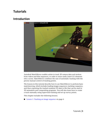
  • 1. Tutorials Introduction Autodesk MatchMover enables artists to track 3D camera data and motion from videos and film sequences, in order to more easily insert CG elements into a scene. MatchMover combines the ease of automatic tracking with the precise manual control of tracking points. The lessons in this tutorial describe how to use MatchMover to perform basic matchmoving, which includes loading images sequences, tracking a sequence, and then exporting the tracked rendered 3D data to file that can be used in 3D animation and compositing programs. You will also learn how to create a track manually using supervised tracking and set up survey points. This chapter includes the following lessons: ■ Lesson 1: Tracking an image sequence on page 6 Tutorials | 5
  • 2. Lesson 2: Using supervised tracking on page 18 ■ Lesson 3: Object-based tracking on page 35 ■ Lesson 4: Motion capture on page 45 Lesson 1: Tracking an image sequence Introduction In this lesson you will learn how to track a sequence in 3D using MatchMover’s automatic tracking engine, inspect the results, and export the result to one of MatchMover’s supported file formats. The automatic tracking feature locates good tracking points in the image, and then tracks them through the sequence. In this tutorial you will learn how to: ■ Load an image sequence. ■ Use the automatic tracker to compute the 3D camera path and the 3D scene. 6 | Chapter 1 Getting Started
  • 3. Navigate in the project with a 3D view to visualize and inspect the tracking results. ■ Render a preview sequence. ■ Export the tracking results to a supported file format. Lesson setup To ensure the lesson works as described, do these steps before beginning: 1 Start MatchMover and ensure that it is set to Light mode. To set MatchMover to Light mode, select Light from the MatchMover toolbar. Although this tutorial is designed for Light mode, it can be completed using MatchMover Full mode. 2 If you have not already done so, copy the Tutorials folder from its installation location to your a project directory. The Tutorials folder can be found in the Help folder of MatchMover’s installation location: Help/Tutorials. Loading the image sequence The first step in matchmoving is to load the image sequence you want to track. NOTE You can bypass this section of the lesson by openningBasic_Sequence.mmf. This file can be found in the Tutorials/Basic directory. You can then proceed to Running the automatic tracker on page 10. To load an image sequence 1 Select File > Load Sequence or click the Load Sequence icon in the toolbar. The Load Sequence window appears. Lesson 1: Tracking an image sequence | 7
  • 4. 2 In the Load Sequence window, browse to the location of the MatchMover Tutorials/Basic directory, and select lion000.jpg, which is the first image in the sequence. 3 Click Details. Information about the image sequence, such as its length as well as preview images, are displayed in the Details section of the Load Sequence window. The video you use for this lesson is in the interlaced PAL format, which means you need to set MatchMover sequence options for this type of video. 4 In the Sequence Options section, select Lower field first from the Interlace drop-down list. 5 In the Camera Settings section, select 25 fps from the Frame Rate drop-down list. 8 | Chapter 1 Getting Started
  • 5. Leave Motion set to Free because in this example, the camera does not follow any of the motion types specified in the list. To play the image sequence 1 Select Sequence > Play or click the play button which is in Play Sequence Toolbar at the bottom of the Workspace. Note that when you play the beginning of the sequence it is slightly jerky. This is because the sequence is loading into your computer’s RAM. After the images are in the cache, the sequence plays smoothly. The size of the current cache is displayed in the bottom-right corner of MatchMover user interface. Since the image sequence is only 50 frames, it plays back too quickly to closely examine. Changing the play mode to PingPong will continuously loop the sequence back and forth, making it easier to check the sequence motion. Lesson 1: Tracking an image sequence | 9
  • 6. 2 Select Sequence > Play Mode > PingPong or click the PingPong button in the Play Sequence Toolbar. 3 To stop the playback, click the Stop button or press Esc. TIP To play the scene manually, you can press Ctrl, click anywhere in the image, and drag the pointer to the left or to the right. 4 To go back to the first frame, press Ctrl+Home (Windows) or Command+Home (Mac) or press . Running the automatic tracker You can use the automatic tracking feature to have MatchMover select the best location of place track points in the image sequence. NOTE You can bypass this section of the lesson by openningBasic_Calibrated.mmf. This file can be found in the Tutorials/Basic directory. You can then proceed to Checking the tracking results on page 12. To run the automatic tracker 1 Select 2D Tracking > Automatic Tracking or click the Run the Automatic Tracking icon . The Automatic Tracking window appears listing the steps in the automatic matchmoving process. 10 | Chapter 1 Getting Started
  • 7. 2 Click Run. Colored indicators display beside the option name to show you the status of each step. After MatchMover has computed the camera path, a collection of 3D points are displayed as cross-hairs in the Workspace. The points are also represented by colored icons in the Project window in the Point Track > Auto Tracks folders. Lesson 1: Tracking an image sequence | 11
  • 8. The colors indicate the quality of the tracking, where green indicates good, yellow fair, and red bad tracking. Some grayed tracks have not been reconstructed, which means that MatchMover considered them unfit to calculate. Checking the tracking results To check the results of the automatic tracking you can: ■ View the track quality by looking at the cross-hairs superimposed on the Workspace, or by view the color icons in the Auto Tracks folder. Most of your reconstructed tracks should be green, a few yellow, and none red. ■ View the reconstructed 3D scene, and check to ensure that it is consistent with the real scene. ■ Render a video sequence where the 3D objects are superimposed on the image sequence and check to ensure that the integration is seamless. To check the tracking results in 3D space 1 Click the 3D space icon that is located in the top left of the workspace view. 12 | Chapter 1 Getting Started
  • 9. MatchMover switches to 3D mode. The tracks are now displayed as 3D cones rather than cross-hairs. 2 Use the following Navigation tools to examine the tracking: ■ Click-hold the Dolly icon to move backward and forward in the space. ■ Click-hold the Orbit icon to view the space in 360 degrees. When orbiting the camera, the 3D View automatically orbits around the selected 3D object, point cloud, or camera. When you navigate in the 3D scene, you can recognize the different elements of the scene, such as the lamppost, statue and wall, as well as the camera path. Lesson 1: Tracking an image sequence | 13
  • 10. 3 To center the view on a track, select it, then select View > Look At. 4 To view the Workspace through the computed camera with the image in the background, select View > Lock on Camera or click the icon. When viewing the Workspace, you can use of the location of the 3D cones to judge the potential orientation of any elements that you might want to introduce into the scene. 5 If the 3D cones appear too big or small, you can change their size by selecting the Project tab in the Parameters window. Change the 3D Helper size value from 1 to 0.5. 14 | Chapter 1 Getting Started
  • 11. Rendering the tracked image sequence After you have created and checked the quality of the 3D tracking in the Workspace, you can render the scene in a video format to further check its quality. You can also export the tracked sequence to a file format that you can open in your favorite 3D animation or compositing program. To render the tracked sequence 1 Select 3D Scene > Render Setup. The Render Setup window appears. 2 In the Render Setup window, click Setup/Browse and do the following: ■ Type a file name for your rendered sequence. ■ From the File type list, select an output file format. ■ Click Save. 3 From the Resolution list, select 50%. 4 In the Options section, turn on Antialiasing. 5 Click Render. The Render window appears, displaying your rendered sequence with 3D cones composited on your original image sequence. With perfect tracking, the 3D cones should appear as if they were part of the scene. Otherwise, you would notice slight discrepancies between the motions of the real scene and the 3D elements. Lesson 1: Tracking an image sequence | 15
  • 12. Now that you have automatically tracked a PAL video sequence and verified it by rendering it, you can export the results to a file that can be opened in your favorite animation or compositing software. 6 Select File > Export or click the icon. The Export window appears. 7 In the Export window, do the following: ■ Type a name for your exported file ■ From the File type list, select a format for you exported file. For example, to open your tracked image sequence in Maya, select Maya (*.ma). ■ Click Save. The image sequence is exported to the specified file format for use in your 3D animation or compositing program. 16 | Chapter 1 Getting Started
  • 13. Beyond the lesson In this tutorial you learned how to: ■ Load an image sequence. ■ Use the automatic tracker to compute the 3D camera path and the 3D scene. ■ Navigate in the project with a 3D view to visualize and inspect the tracking results. ■ Render a preview sequence ■ Export the tracking results to a file format that is supported by your favorite 3D animation or compositing program. For more information and related techniques about MatchMover, refer to the MatchMover Help. Lesson 1: Tracking an image sequence | 17
  • 14. Lesson 2: Using supervised tracking Introduction For complicated scenes, it may be necessary to manually control the tracking process by editing or deleting tracks that were created by MatchMover’s automatic tracking feature. Using a supervised tracking technique, you can place tracks manually by specifying the key points or then edit their location if required. Matchmover then generates a whole point trajectory based on the manually placed points. In this lesson, you will learn how to place tracks manually in a scene using. The image sequence you use for the lesson was shot against a green background using professional equipment. The green background serves as a typical support for the actors, and would be replaced by virtual decors. The gray crosses on the background will help you accurately place tracking points in the scene. The image sequence appears courtesy of Clear Ltd. In this lesson you will: ■ Load a sequence. 18 | Chapter 1 Getting Started
  • 15. Create and edit tracks manually. ■ Launch the solver. ■ Define a coordinate system. ■ Add a 3D object to verify the tracked sequence. Lesson setup To ensure the lesson works as described, do these steps before beginning: 1 Start MatchMover and set it to Full mode. To set MatchMover to Full mode, select Full from the MatchMover toolbar. 2 If you have not already done so, copy the Tutorials folder from its installation location to your a project directory. The Tutorials folder can be found in the Help folder of MatchMover’s installation location: Help/Tutorials. Creating a point track In matchmoving, creating a point track by manually placing points in a scene is also known as a hard track. The automatic process that you completed in lesson 1 is different from supervised tracking in that many tracks are handled at the same time and 3D coherency is used while tracking. For supervised tracking, only one track is handled at a time. Also, when supervised tracks are present before launching the automatic process, they are used in the 3D coherency checking. NOTE You can bypass this section of the lesson by openningShot_tracked.mmf. This file can be found in the Tutorials/Supervised_Shot directory. You can then proceed to Adding tracking points on page 24. Lesson 2: Using supervised tracking | 19
  • 16. To load the image sequence 1 Select File > Load Sequence or click the Load Sequence icon. The Load Sequence window appears. 2 In the Load Sequence window, browse to the location of the MatchMover Tutorials/Supervised_Shot directory, and select shot01.jpg, which is the first image in the sequence. 3 Click OK. MatchMover loads the sequence into the Workspace. Placing a track point When placing tracks manually, try to cover as much of the scene as possible. The tracked points should be points that can be accurately localized in the image and represent physical points such as markings, corners, or shadows.To help with the accuracy of the manually placed points you will place tracks on the most contrasted areas. In the image sequence, you will use the gray X’s that appear on the green background of scene to help position your tracking points. 20 | Chapter 1 Getting Started
  • 17. For more information about placing tracks, see Supervised 2D tracking on page 132. To place a track point in the scene 1 Go to the first frame of the sequence. 2 Select 2D Tracking > New Track or click the New Track icon. When you drag the cursor over the Workspace, it changes to cross-hairs. 3 Position the cross-hairs near the one of the gray X’s that appear in the scene. Use the location shown in the image below as a guide. Use the Magnifier window view below the Project window to help you precisely position the location of the new point. Lesson 2: Using supervised tracking | 21
  • 18. Corner areas are often good locations to place the track points. The extremity areas have less contrast and do not allow you to visually locate the point as precisely as the intersections and can introduce a higher risk of ending up with a “sliding” track point. 4 Click-hold the location of the new point. A Magnifier window appears around the area you placed the point. This is another window you can use to help place the track point accurately. 5 Release the mouse button to create the track point. A window labeled Track 01 appears in the Workspace. The presence of the window indicates that the track point is still selected. 6 With the track point selected, select 2D Tracking > Track Forward or click the icon to run 2D tracking for your point. While the point is being tracked, the Tracking Monitor window appears showing you the tracking progress. After the point tracking is complete, its trajectory line appears on the image. You may notice that the trajectory line has green, yellow, and possibly, red segments. The red segments indicate areas where the tracking slides or is of low quality. 22 | Chapter 1 Getting Started
  • 19. You can correct the sliding track by manually adjusting the point positions where the track has drifted significantly. In the next section of the lesson, you adjust the point positions to improve the tracking quality. Editing a point track To improve the quality of your hard track, you can adjust the location of a tracking point and re-run the tracking process. To adjust tracking point positions 1 Using the time line controls, go to a frame where the track drifts. This is indicated by the red sections. 2 In the Workspace, click-hold the tracking point and move it in the direction that will improve the tracking such as closer to an inside corner of the gray X’s. Use the Magnifier window that appear around the point to help you adjust the point's position. 3 Release the mouse button. Notice that when you release the mouse button, MatchMover clears the end of the trajectory. That is because the tracked data is no longer compatible with new position of the point. This means that you must re-compute the trajectory based on the new point position. 4 With the track point selected, select 2D Tracking > Track Forward or press F3, which is the Track Forward keyboard shortcut. MatchMover calculates a new trajectory for the track. Lesson 2: Using supervised tracking | 23
  • 20. To make the track trajectory smoother, you can update the tracked data between the initial point and the point's new location by using bi-directional tracking. 5 Select 2D Tracking > Bidirectional or click the Run Track Full icon. You can check the smoothness of your edited track by centering your view on the current track. 6 Select View > Lock on Track or click the icon. 7 Play the image sequence in PingPong mode by clicking followed by . Notice that when the sequence plays back section of the sequence you have tracked, the view is locked to the motion of the edited track. 8 Stop the sequence playback by clicking the icon. 9 To get a close-up view of the track, press Ctrl+Alt and drag the mouse up and down to zoom in and out of the Workspace view. If you are not satisfied with the quality of the track, adjust the point and run the tracking again. TIP If you notice a jump in the trajectory, you can adjust the point position by pressing the arrow keys. Select Preferences > 2D Tracking to adjust the nudge step. Use shift to multiply the nudge step by 10. If needed, a key point is inserted at the current edited frame. Adding tracking points Adding more tracking points to your scene improves the overall quality of the tracking. Open the file for the lesson To ensure this lesson works as described, open the scene file named Shot_tracked.mmf. This file is in the Tutorials directory that you copied from 24 | Chapter 1 Getting Started
  • 21. the MatchMover installation directory to a local directory: TutorialsSupervised_ShotShot_tracked.mmf. Supervised tracking Eight tracks have been added to the image sequence. In this section of the lesson, you will add more tracking points starting with Track 9. To make the tracking process quicker, you can use MatchMover's keyboard shortcuts to create the track and run the forward tracking. To create a new track 1 Using the image below as a reference, place the mouse pointer in the location shown in the image below. Use the Magnifier window to help find the correct location for the tracking point. Lesson 2: Using supervised tracking | 25
  • 22. 2 Create the tracking point by pressing Shift+right-click. The tracking begins then stop around frame 15. Track 09 appears in the Workspace and is also added to the track points in the Project window. 3 To run forward tracking press F3. A window appears in the Workspace indicates that the tracking quality is too low for MatchMover to continue the trajectory. 4 Click OK. The reason the tracking quality is so low is that the actor’s body hides the area you want track in the sequence. 5 In the time line, double the last frame of the Track 9 trajectory. 26 | Chapter 1 Getting Started
  • 23. The Parameters window now displays the parameters for the tracked point under the Track 09 tab. Since the tracked point’s trajectory cannot continue to be tracked, you can change the status of last frame by setting it to an end keyframe. This means that MatchMover will not track forward past this frame. 6 Select 2D Tracking > Set Key > End. The End status of the keyframe is indicated in the Track 9 Parameters window in the Status field. 7 With Track 09 selected, advance the sequence one frame at a time by pressing Ctrl+right arrow key. As you advance, the tracked point and its trajectory is hidden between frames 16 and 28, then re-appears at frame 29. Since the track is likely to disappear again, this time behind another obstacle, you can track the point frame-by-frame using the Step-tracking mode. 8 To use Step-tracking mode, press Alt+right arrow to continue tracking forward from frame 29. At frame 31, a window appears indicating that the tracking quality is too low to continue tracking. Lesson 2: Using supervised tracking | 27
  • 24. TIP Use the Magnifier window to get a better view of the obstacles that are hiding the Track 09 trajectory path. 9 At frame 31, change the status of the keyframe to End by selecting 2D Tracking > Set Key > End. 10 Go to frame 44 and press F3 to run forward tracking. Track 09 is now complete and set in the scene. To check the quality of the track 1 Ensure that Track 9 is selected in the Workspace. 2 Click the padlock icon at the bottom right of the Magnifier window. This makes the Magnifier window the only active view. 3 Select View > Skip Untracked or click the icon. 4 Play the image sequence in PingPong mode by clicking followed by . Notice that MatchMover only plays the sections of Track 09 that have been tracked. The frames that could not be tracked because of obstacles in the scene are not played. 5 Click the lock icon to make the Workspace window active again. 6 Select View > Skip Untracked so that all frames play when the sequence is played back. Calibrating the camera In MatchMover, a camera is characterized by its internal parameters such as Principal Point, Focal Length, Pixel Aspect Ratio, and Distortion. In some cases, you may already have information about the camera. For example, you may know that it is a 24 ×36 mm film back camera with a 35 mm lens. You can then input this information into MatchMover before launching the camera tracker. For this lesson, you will calibrate the camera using MatchMover's default values. This process of calibrating a camera involves reconstructing 28 | Chapter 1 Getting Started
  • 25. the 3D points corresponding to the 2D tracks and computing the camera path for all the sequences or frames and all the objects in one solve. NOTE You can bypass this section of the lesson by openningShot_solved.mmf. This file can be found in the Tutorials/Supervised_Shot directory. You can then proceed to Creating a coordinate system on page 29. To calibrate the camera 1 Run the calibration by selecting 3D Tracking > Solve For Camera or by clicking the Solve For Camera icon. The camera is calibrated. 2 Click the 3D space icon that is located in the top left of the Workspace view. The view switches to 3D mode and the tracks are now displayed as 3D cones rather than cross-hairs. A camera icon is placed in the Workspace, which represents the camera you calibrated. 3 Select View > Lock On Camera or click the Lock on Camera icon. 4 Play the sequence to check the tracking. Notice the image sequence plays back from the perspective of the camera. Creating a coordinate system MatchMover manages a set of user-defined coordinate systems with respect to the cameras and 3D points in the Workspace. If no coordinate system is specified, MatchMover chooses an arbitrary one. You can define a coordinate system in order to facilitate the manipulation of your exported project in a 3D package. If no point relations have been set up, MatchMover aligns the coordinate system on the computed position of the camera for the first frame; the default is the camera looking towards Z and Y as Up axis, but this changes according to your project's 3D parameters if you selected a different up axis. NOTE You can bypass this section of the lesson by openningShot_coordsys.mmf. This file can be found in the Tutorials/Supervised_Shotdirectory. You can then proceed to Add a 3D object on page 32. Lesson 2: Using supervised tracking | 29
  • 26. Open the file for the lesson To ensure this lesson works as described, do the following: 1 Ensure that it is set to Full mode. To set MatchMover to Full mode, select Full from the MatchMover toolbar. 2 Ensure that MatchMover is set to 3D mode. To switch MatchMover to 3D mode, click the 3D space icon that is located in the top left of the Workspace view. If a 2D space icon appears instead, then MatchMover is already in 3D mode. 3 If you have not already done so, copy the Tutorial folder from its installation location to your a project directory. 4 Open the scene file named Shot_solved.mmf. This file is in the Tutorials directory that you copied from the MatchMover installation directory to a local directory: TutorialsSupervised_ShotShot_solved.mmf. Setting up the coordinate system To set up the coordinate system 1 In the Project window, right-click the Coordinate Systems folder and select New Coordinate System from the pop-up menu. A grid and coordinate indicators appear in the Workspace. 2 In the Parameters window, click the Coord 01 tab. For your new coordinate system values, you will use Track 05 as the origin. This point is the center of the grid and floor of the scene. 3 In the General section, select Track 05 from the Origin list. 30 | Chapter 1 Getting Started
  • 27. 4 To set the grid value, in the General section, do the following: ■ In the Distance field, type 20.00. This value defines the distance between two points in the scene. ■ From the From list, select Track 07. ■ From the To list, select Track 09. These two points provide tracking locations in the corners of the room, making them well suited for defining the boundaries of the coordinate system. 5 Click the Axis 1 tab and do the following: ■ Select Y from the X, Y, and Z list. ■ Select normal to 3 points from the list to the right of Y. ■ For the three points, select Track 03, Track 04, and Track 05 from the lists located under Y. These settings create a Y-based coordinate system using three points that are located on the ground of the scene. 6 Click the Axis 2 tab and do the following: ■ Select Z from the X, Y, and Z list. ■ Select through 2 points from the list to the right of Z. Lesson 2: Using supervised tracking | 31
  • 28. For the two points, select Track 01 and Track 02 from the lists located under Z. These settings create a Z-axis as the second axis which is based on the crosses on the wall of the scene background. 7 Click Apply Coordinate System to validate your coordinate settings. The defined coordinate system appears in the Workspace. Add a 3D object Now that you have defined a 3D coordinate system in MatchMover, you can import an object into the Workspace and check its behavior in the scene. NOTE You can bypass this section of the lesson by openningShot_object.mmf. This file can be found in the Tutorials/Supervised_Shotdirectory. To add a 3D object 1 Select 3D Scene > New Primitive > Pyramid or click the from the primitive list located on the Toolbar. The pyramid primitive appears in the Workspace at the origin of the coordinate system. A Pyramid tab appears in the Parameters window displaying the pyramids position and scale. The pyramid is too large for the scene. You can make the pyramid smaller by using MatchMover’s scaling tools. 2 If the pyramid is not selected, select it now by clicking it in the Workspace or by clicking Pyramid in the Project window under the 3D Scene folder. 32 | Chapter 1 Getting Started
  • 29. 3 Press the Tab key to select the scaling tools. The scaling tools appear as a series of light blue, dark blue, green, and red cubes surrounding the pyramid. 4 Click-drag one of the light blue cubes inward until the Scale X, Y, and Z values are 0.48, or until the base of the pyramid is on the grid. Notice that as you drag the cursor, the X, Y, and Z values are scaled uniformly. 5 Play the sequence in PingPong mode. Notice that the tip of the pyramid is out of the camera view. You can use the move tool to change the pyramid’s position so that it remains in the camera view throughout the sequence. 6 Select the dark blue arrow and move the pyramid along the Z-axis toward the front of the scene until its Pos Z value is about -4.20. 7 Play the sequence in PingPong mode. Notice that the pyramid remains in the camera view throughout the sequence. Lesson 2: Using supervised tracking | 33
  • 30. You can now export the sequence and verify its tracking quality in your favorite 3D animation or compositing program. 8 Select File > Export to export the scene to a file format supported by your 3D animation or compositing program. The Export window appears. 9 In the Export window, do the following: ■ Type a name for your exported file. ■ From the File type list, select a format for you exported file. For example, to open your tracked image sequence in Maya, select Maya (*.ma). ■ Click Save. The image sequence is exported to the specified file format. Beyond the lesson In this lesson you learned how to: ■ Create and edit tracks manually. ■ Launch the solver and calibrate a camera. ■ Create a new coordinate system. ■ Add a 3D object to verify the tracked sequence. For more information and related techniques about MatchMover, refer to the MatchMover Help. 34 | Chapter 1 Getting Started
  • 31. Lesson 3: Object-based tracking Introduction In this lesson, you will learn how to track an object, such as an image plane in MatchMover using a 3D model of it. This is a useful technique in situations such as the following: ■ Augmenting a real set for which some 3D information is available as manual measurements or CAD data. ■ Matchmoving characters from a Cyberware scan. ■ Tracking complex shots of a set using data from an active scanning device (LIDAR). Using this technique ensures that, in any case (even with low or zero parallax), the camera path will be exactly consistent with the 3D geometry of the tracked element. The image sequence you will use in this lesson was shot using a hand-held DV camcorder. Lesson 3: Object-based tracking | 35
  • 32. In this lesson you will learn how to: ■ Import a 3D mesh. ■ Create tracks and survey points attached to vertices of the mesh, using the “elastics” feature. Lesson setup To ensure the lesson works as described, do these steps before beginning: 1 Start MatchMover and set it to Full mode. To set MatchMover to Full mode, select Full from the MatchMover toolbar. 2 If you have not already done so, copy the Tutorials folder from its installation location to your a project directory. The Tutorials folder can be found in the Help folder of MatchMover’s installation location: Help/Tutorials. Importing the 3D mesh Load the footage NOTE You can bypass this section of the lesson by openningElastic_Import_Scene.mmf. This file can be found in the Tutorials/Elastics directory. You can then proceed to Set up the trackers and the survey points on page 39. To load the image sequence 1 Select File > Load Sequence or click the Load Sequence icon. The Load Sequence window appears. 36 | Chapter 1 Getting Started
  • 33. 2 In the Load Sequence window, browse to the location of the MatchMover Tutorials/Elastics directory, and select Elastic00.jpg, which is the first image in the sequence. 3 In the Load Sequence window, under Sequence Options, set Interlace type to Lower field first. 4 Under Camera Settings, set Frame Rate to 24 fps (Frames Per Second). Leave Motion set to its default setting of Free. 5 Click OK. Import the 3D mesh To import the 3D mesh 1 Click the 3D space icon that is located in the top left of the Workspace. The view switches to 3D mode. A camera icon and grid is placed in the Workspace. 2 Select File > Import, or right-click in the Workspace and select Import Scene from the pop-up menu. Lesson 3: Object-based tracking | 37
  • 34. The Import Object window appears. 3 In the Import Object window, select Wavefront Ascii Model (*.obj) from the Files of Type list. 4 Browse to the location of the Tutorial/Elastics directory, and select Box.obj. A 3D mesh of the box appears, in wireframe, in front of the image plane. This mesh will now be used as a reference for the 3D tracking. This ensures that the solution will be consistent with this geometry even though this shot holds little parallax. 38 | Chapter 1 Getting Started
  • 35. Set up the trackers and the survey points You can use survey points to analyze the results of 3D tracking and to isolate specific frames or points where adjustment may be necessary. NOTE You can bypass this section of the lesson by opening Elastic_SetUp_Elastics.mmf. This file can be found in the Tutorials/Elastics directory. You can then proceed to Solve and check the tracking results on page 43. 1 Using the Pan and Dolly controls, make sure both the imported 3D object, which represents the shape of the box, and the image plane are clearly visible. For example, set up your viewing position and angle similar to the image below. Lesson 3: Object-based tracking | 39
  • 36. 2 Make sure that the Magnifier window is open by selecting Window > Magnifier Window. 3 Click-hold the vertex located at the top right corner of the 3D object and move the cursor to the position of the same corner in the image plane. As you drag the curser toward the image plane, a red elastic line follows, joining the selected vertex and the image plane. 40 | Chapter 1 Getting Started
  • 37. NOTE If you want to abort the operation while dragging the cursor, drag the cursor out of the image plane. The elastic line becomes dashed, meaning nothing will happen when you release the mouse button. 4 Release the mouse button. The elastic is now blue and a new track, Track 01, is created with a point in the current frame (visible in the track view). Lesson 3: Object-based tracking | 41
  • 38. Survey point information issued from the selected vertex is automatically associated to the track. You can see this information in the Parameters window under the Track 01 tab. Click the 3D tab and look in the Survey Info section. 5 If necessary, you can adjust the position of the tracking point by clicking it in the Magnifier window. 6 Run forward tracking on the point by pressing F3. You can check the quality of the new track by playing the sequence. 7 Press F2 to play the sequence. To get a close-up view of the tracking point, you can lock the sequence play to the Magnifier window. See Supervised 2D tracking on page 132. 8 Go to the first frame and repeat steps 3 to 7 for all the corners of the box. Your project should now look similar to the image below. 42 | Chapter 1 Getting Started
  • 39. NOTE If needed, you can change the viewpoint to better view the 3D object’s vertices and locations on the image plane. You can move and rotate the object in the Workspace by selecting it and using the object manipulator. The transform you apply to the object will not be used in the survey information, unless you specify it by turning on Use Object Transform in the Survey Info section tab of the track Parameters window. Solve and check the tracking results To solve and check the tracking results 1 Select 3D Tracking > Solve For Camera or press F9. After the camera completes the solve, blue cones appear at the tracking points on the 3D object and the new tracks appear in the Track window. When you look in the Track window, notice that some of your new tracks have yellow segments, indicating that acceptable, but not good tracking. This occurs because the constraints induced by the 3D points are quite strong, while the footage quality does not allow the points to reach a high accuracy on the 2D points locations. 2 Select View > Lock on Camera. The Workspace view now displays the cameras perspective. Lesson 3: Object-based tracking | 43
  • 40. 3 Press F2 to play the sequence and check the alignment of the mesh with the image. Beyond the lesson In this lesson you learned how to: ■ Import a 3D mesh. ■ Create tracks and survey points attached to vertices of a mesh, using the “elastics” feature. For more information and related techniques about MatchMover, refer to the MatchMover Help. 44 | Chapter 1 Getting Started
  • 41. Lesson 4: Motion capture Introduction In addition to conventional matchmoving, such as automatically capturing the 3D camera paths from 2D live-action video sequences, you can use Autodesk MatchMover to perform motion capture. Motion capture is the process of tracking, in 3D, the motion of non-rigid objects such as a human body, face, or a piece of cloth. In this lesson, you will capture the motion of an animated character from two synchronized videos sequences. The sequences were captured as DV video using two static cameras. This provides you with the basic setup required for motion capture. In this lesson you will: ■ Create a motion capture project. ■ Synchronize two video sequences. Lesson 4: Motion capture | 45
  • 42. Create motion tracks for two synchronized video sequences. ■ Calibrate the camera to obtain camera parameters. ■ Build a skeleton line representation of an actor’s motion. Lesson setup To ensure the lesson works as described, do these steps before beginning: 1 Start MatchMover and ensure that it is set to Full mode. To set MatchMover to Full mode, select Full from the MatchMover Toolbar. 2 If you have not already done so, copy the Tutorials folder from its installation location to your a project directory. The Tutorials folder can be found in the Help folder of MatchMover’s installation location: Help/Tutorials. Synchronizing the sequences Load two sequences The first step in synchronizing the video sequences for motion capture is to load both sequences into MatchMover. NOTE You can bypass this section of the lesson by opening Load_sequences.mmf. This file can be found in the Tutorials/Mocap directory. You can then proceed to Synchronize the sequences on page 47. To load the image sequences 1 Select File > Load Sequence or click the Load Sequence icon. The Load Sequence window appears. 46 | Chapter 1 Getting Started
  • 43. 2 In the Load Sequence window, browse to the location of the MatchMover Tutorials/Mocap directory, and select Motion1_00.jpg, which is the first image in the first sequence. 3 In the Load Sequence window, set the following: ■ In the Sequence Options section, select Lower field first from the Interlace drop-down list. ■ In the Camera Setting section, set Motion to Fixed. This setting will impose a constraint attached to the camera, representing a static camera. ■ Set Frame Rate to 25. 4 Load the second sequence by repeating steps 1 to 3. In the Load Sequence window, browse to the location of the MatchMover Tutorials/Mocap directory, and select Motion2_00.jpg, which is the first image in the second sequence. The two sequences are represented by different colors in the Track View and Project windows. Synchronize the sequences Because you need to adjust these sequences to the same time reference, you will synchronize them by specifying a synchronization tick. To do this, you need to identify a visible event that you can easily see in both image sequences. For example, while you are shooting the sequences, you can use a specific device, such as a flash or a clapperboard, to create the event. NOTE You can bypass this section of the lesson by opening Synchronize_sequences.mmf. This file can be found in the Tutorials/Mocap directory. You can then proceed to Creating motion tracks on page 49. For this lesson, you can use the instant the actor's left foot begins to touch the floor. In Sequence 01, it occurs at frame 9 (9/50) and for Sequence 02 it Lesson 4: Motion capture | 47
  • 44. occurs at frame 58 (7/50). You can see this information displayed on the top-left corner of the image viewport. To synchronize the sequences 1 In the Project window, click Sequence01. 2 In the Parameters window, in the Synchronization section, turn on Synchronized at Frame and set it to 9. 3 Repeat steps 1 and 2 for Sequence02, setting the Synchronized at Frame to 7. Notice that in the Project window the sequence icons have changed, indicating that they each have a specified synchronization frame. 4 To change the workspace viewport so that you can see both sequences at the same time, from the Toolbar, click icon and select Two Side by Side from the list. 5 Right-click the left viewport and select Synchronize Time from the pop-up menu. 48 | Chapter 1 Getting Started
  • 45. The information displayed in the top-left corner of this viewport is now displayed in bright green, meaning it will update its own time using the synchronization information specified. 6 Right-click the right viewport and select Synchronize Time from the pop-up menu. 7 With the right viewport still active, select any frame between 51 and 101 in the Time line. You can now play the sequence from this point in the Time Line to check that the sequences are synchronized. Click the icon to play the sequence. When you look at the start of Sequence 02 at frame 51 in the right viewport, notice in the left viewport that Sequence 01 is at frame 2. It is this difference that allows us to have a good synchronization between the sequences. Creating motion tracks In this section of the lesson, you create a motion track of the actor’s movements. NOTE You can bypass this section of the lesson by opening Motion_solved.mmf.mmf. This file can be found in the Tutorials/Mocap directory. You can then proceed to Finalizing your motion capture project on page 53. The first step in this process is to create a new point track group that you will use to place the actor's tracks. To create a new point track group 1 In the Project window, right-click the Point Tracks folder and select New Group from the pop-up menu. 2 In the Parameters window, click the Group 01 tab. 3 In the Label field, select Group 01and type Actor. 4 In the Options section, select Non-rigid (motion capture) from the Motion list. This option specifies that the point track belonging to the new group will be for the motion of non-rigid objects. Lesson 4: Motion capture | 49
  • 46. Creating point tracks In this section of the lesson, you place track point on markers that are attached to the actor. There are 18 markers attached to the actor, but for this section of the lesson, you use only six for your tracking points. When creating a motion track, you must place your track points on the same marker in both sequences. For example, if you place Track 01 on the white marker located on the right side of the actor’s head in Sequence01, you must also place Track 01 on the same marker in Sequence02. Be aware that some tracks may need manual adjustment as can be the case when using supervised tracking. For example, in a few of the frames, MatchMover confuses the motion of the actor's saber with the motion of the markers on the actor's leg and includes the saber’s motion in the track. The easiest markers to track in both sequences are located on the actor's head and on the legs. In all cases, try to choose the most visible markers in your sequences. For information about supervised tracking, see Lesson 2: Using supervised tracking on page 18. To create the track points 1 Go to frame 51 in the Time Line. The left viewport now displays the first frame of Sequence 01and the right viewport now displays the first frame of Sequence 02. 2 Select 2D Tracking > New Track or click the New Track icon. When you drag the cursor over the Workspace, it changes to cross-hairs. 3 In Sequence 01, position the cross-hairs over the white mark located on the right side of the actor's head. Use the Magnifier window view below the Project window to help you precisely position the location of the new point. 4 Click to create Track01 for Sequence 01. 50 | Chapter 1 Getting Started
  • 47. 5 In Sequence 02, position the cross-hairs over the same marker, and click to create Track01 for Sequence 02. Use the locations shown in the image below as a guide. 6 With the track point selected, select 2D Tracking > Track Forward or click the icon to run 2D tracking for your points. 7 Using steps 2 to 6, create five more track points. Your project should look similar to the one in image below. Lesson 4: Motion capture | 51
  • 48. Performing an initial solve Before you can perform the camera solve, you must remove the two-frame shift between the two sequences. The first two frames (0-1 in the Time Line) only appear in Sequence 01, and the last two frames (100-101 in the Time Line) only appear in sequence Sequence 02. Since no 3D information can be derived for these frames, you need to specify that the frames are not solved. To solve for the camera 1 In the Track View, Shift-select the time interval of the first two frames (0 and 1) of Sequence 01. 2 Right-click in the Track View and select Set Frames > Do Not Solve from the pop-up menu. 3 Repeat steps 1 and 2 for Sequence 02. For Sequence 02, select the time interval of the last two frames in the sequence (100-101). 4 Deselect the time interval by Shift+right-clicking in the Track View. 5 Solve for the camera by selecting 3D Tracking > Solve For Camera or by clicking the Solve For Camera icon. The camera is now calibrated. 52 | Chapter 1 Getting Started
  • 49. Finalizing your motion capture project In this section of the lesson, you will add three tracks that correspond to points in the scene’s static background. This is the minimum number of points required to define a coordinate system. Creating these tracks defines a 3D coordinates with respect to a world coordinate system attached to the background, which is very useful in motion capture. This step might not be necessary if all you need is to compute the 3D trajectories with respect to an unspecified coordinate system In the last step of the lesson you will create skeleton lines which will better display the motion captured and of the tracked scene. Since there are 18 markers attached to the actor, each potentially a track point, you can either continue adding tracks to your current project, or you can open Actor_tracked.mmf which has tracks already created for all 18 markers. This file can be found in the Tutorials/Mocap directory. You can also start this section of the lesson using Motion_solved.mmf. In this file, six markers have been tracked. This file can be found in the Tutorials/Mocap directory. Lesson 4: Motion capture | 53
  • 50. If you want to add the tracks yourself, do so before continuing the lesson. To create point tracks in the background 1 In the Project window, select the Point Tracks folder. Since the point tracks that you will create for the background are for static, rigid objects, selecting the Point Tracks folder ensures that your new point tracks are not added to the Actor Point Tracks folder. 2 In the first frame of Sequence01, place a track point on the floor of the scene by selecting 2D Tracking > New Track or clicking the New Track icon. You can try to use the square patterns to locate easily recognizable locations on the floor as you will need to place a track point in the same location in Sequence02. NOTE You can try to use the square patterns to locate the points on the floor. Once the first track is placed, you do not need to run the Track Forward on it, because the sequence was shot with a fixed camera, and MatchMover detects this through the “fixed” motion constraint. 3 In the first frame of Sequence02, place the same track point in same location as you did in the first frame of Sequence01. This point is reconstructed in space right away, based on the existing camera calibration (solve). If the point is in the wrong location in one of the sequences, the cross-hairs will appear in red. This can often happen if your video sequences are low-resolution, compressed footage. 4 Repeat steps 2 and 3 to create the remaining two track points for Sequence01 and Sequence02. The goal is to place track points that define a coordinate system on the ground. 54 | Chapter 1 Getting Started
  • 51. 5 Solve for the camera by selecting 3D Tracking > Solve For Camera or by clicking the Solve For Camera icon. The camera is calibrated with the a coordinate system on the scene’s background. You can now finalize you project by building some skeleton lines. 6 Click the 3D space icon that is located in the top left corner of both viewports. The view switches to 3D mode. A camera icon and grid is placed in the Workspace. You can also switch back to a single viewport by selecting Single Viewport Space from the Toolbar. 7 In the viewport, select the yellow cone that appears at the right side of the actor’s head. This cone represents Track01. 8 Shift-select the yellow cone that appears at the left side of the actor’s head. This cone represents Track02. 9 With both cones still selected, select 3D Tracking > New Relation. 10 In the Parameters window, click the Relation 01 tab. 11 From the Type list, select Line. Lesson 4: Motion capture | 55
  • 52. A line is displayed between the two cones. 12 Repeat steps 7 to 11 for the remaining track points or until you see satisfied with the line reconstruction of your motion capture. NOTE You can open Motion_finalized.mmf to see the entire project. The result should look similar to the one in the following image. 56 | Chapter 1 Getting Started
  • 53. You can export your project to a file format supported by your favorite animation or composition software by selecting File > Export. Beyond the lesson In this lesson you learned how to: ■ Create a motion capture project. ■ Synchronize two video sequences. ■ Create motion tracks for two synchronized video sequences. ■ Calibrate the camera to obtain camera parameters. ■ Build a skeleton line representation of an actor’s motion. For more information and related techniques about MatchMover, refer to the MatchMover Help. Lesson 4: Motion capture | 57
  • 54. 58