1. EXPERIMENT NUMBER 5
Characterization and Use of Bipolar Junction Transistors
Preface:
• Preliminary exercises are to be done and submitted individually.
• Laboratory hardware exercises are to be done in groups.
• Work done in notebooks to be submitted individually.
• The laboratory notebooks to be submitted immediately following the laboratory.
• The laboratory notebooks must include all settings, steps and observations in the
exercises. All statements must be in complete sentences and all tables and figures must
have a caption.
• This laboratory requires technical memorandum to be submitted individually. The
technical memorandums require a specific format, must include specific appendix tables,
and must address the listed questions. Review the associated guidelines.
• Review the guidelines for plagiarism to be aware of acceptable laboratory and classroom
practices.
Bipolar junction transistors (BJTs) are common in many digital and analog applications. The
following laboratory explores BJTs characteristic and their use in digital switching applications.
Objectives:
• Observe the I-V characteristics of both types of BJTs,
• Learn how to use a BJT as a switch, and
• Demonstrate the significance of the Darlington Pair configuration
References:
• EE 121 Handouts
• EE 151 and EE 153 text: Cunningham and Stuller, Circuit Analysis, 2nd Ed. (Houghton
Mifflin Company, Boston, 1995).
• Neamen, Donald A., Electronic Circuit Analysis and Design, 2nd ed., (McGraw-Hill, New
York, New York, 2001), Chap 4.
Background:
Switches are needed in electronics to turn-on a voltage or current of sufficient power to operate a
circuit. Many digital and analog applications use transistor circuits for amplifying the output
current of a microcontroller. The outputs from microcontrollers often can sink current well but
cannot source current. One of the most common circuits to handle this application is a
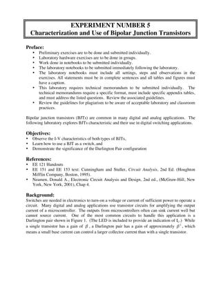
Darlington pair shown in Figure 1. (The LED is included to provide an indication of IC.) While
a single transistor has a gain of ! , a Darlington pair has a gain of approximately ! 2 , which
means a small base current can control a larger collector current than with a single transistor.
2. Vcc Current Gain
One transistor
Two transistors
Ic
1 kΩ
Vin 1 MΩ
Q1
Ib Q2
Figure 1 – Dual-Transistor Darlington Circuit
To illustrate this concept, say a 1 MΩ resistor is placed in series with the base, and Vin is set to 5
V. If the ground connection was moved to the first transistor, Q1 so that only a single transistor
5 V ! 0.7 V
is used in the circuit, the current into the base should approximately be = 4.3 µ A .
1 M"
Assuming β to be 100, the collector current should be about 100 ! 4.3 µ A = 430 µ A . This
current is not enough to turn on the LED. If the ground were connected at the emitter of Q2,
implementing the Darlington pair, the gain is approximately 1002 = 104 , the base current is about
5 V ! 0.7 V ! 0.7 V
= 3.6 µ A , and the collector current is about 104 ! 3.6 µ A = 36 mA .
1 M"
Light Emitting Diodes (LEDs)
A light emitting diode (LED) is a diode that emits light for forward bias conditions. The light
emission increases as the diode current increases. Practically, a minimum current is required to
clearly see the light. LEDs are often used as indicators, e,g, the light appears when a current
threshold is reached.
Preliminary:
(Work on separate paper and turn in at the beginning of the laboratory session.)
• Print the data sheets for Fairchild 2N3904 (npn) and 2N3906 (pnp) transistors. Using these
data sheets, find the DC current gain, collector saturation voltage, the maximum voltage
rating, and the maximum current ratings. Put the results in a table.
• Consider a common-emitter, single-transistor npn-BJT circuit with Rb = 1 MΩ, Rc = 1 kΩ,
and Re = 0. Assume the base-emitter turn-on voltage is 0.7 V and the gain is 100. Calculate
the value of VCC for which the operating point at VBB = 5 V is at the edge of the saturation
region (about VCE = 0.2 V). Calculate the corresponding collector current value. The circuit
design is of a transistor switch that turns an LED “on” when the input is 5V and turns the
LED “off” when the input is 0V.
3. Equipment:
• I-V Curve Tracer
• DC Power Supply
• Breadboard
• Signal Generator
• Oscilloscope
• Fairchild 2N3904 (npn) Transistor
• LED
• Resistors
Experimental Procedure:
(Record specifics in the Laboratory Notebook.)
1. Use the curve tracer to determine the I-V curves of the Fairchild 2N3904 (npn) and 2N3906
(pnp) transistors. Plot or sketch the common-emitter I-V curves.
Q1: What are the approximate collector-emitter voltages at the transition between the
saturation and active regions?
2. Construct the single-transistor npn-BJT switch from the background. Using a T-connector
on the Signal Generator, connect one cable to the Oscilloscope and another to the input of the
switch. Use VCC equals to 5 V. Set the output of the Signal General to a 5Vpp square wave as
the input voltage. Adjust the source voltage for proper on/off operation such that at a low
frequency the LED blinks. Measure the collector current by observing the voltage across the
1-kΩ resistor for low frequency. Refer to figure 1 with reference shifted to the emitter of Q1
thus, excluding Q2 from the circuit.
Q2: How does the experimental value of VCC compare to the calculated value?
Q3: At what frequency does the LED no long blink?
3. Construct the dual-transistor Darlington circuit with two npn-BJTs. Note the change in the
brightness of the LED for low frequencies from the single-transistor case. Observe the LED
indicator as frequency is varied on the input square-wave voltage. Measure the collector
current by observing the voltage across the 1-kΩ resistor for low frequency.
Q4: How does the experimental value of current compare to the background value?
4. For the Darlington circuit, measure the voltage across the 1-kΩ resistor for a set low
frequency as the input voltage is changed. Note the voltage at which the collector current
begins to increase. Generate a vi vs. vo curve.
Q5: Are the voltages reasonable?
Technical Memorandum:
• Memorandum discussion:
(1) Describe, based on your observations, I-V curves of the Fairchild 2N3904 (npn) and
2N3906 (pnp) transistors. What are the approximate collector-emitter voltages at the
transition between the saturation and active regions? (Q1) Does the curve match theoretical
expectations?
(2) Describe, based on your observations, the use of the common-emitter configuration as a
switch with operation across the active region. Does the switch work as expected? How
does the experimental value of VCC compare to the calculated value? (Q2) At what
frequency does the LED no longer blink? (Q3) (Optional: why is there a frequency
dependence?)
(3) Describe, based on your observations, the use of the Darlington configuration as a switch.
Does the Darlington switch work as expected? How does the experimental value of current
4. compare to the background value and the single-transistor value? (Q4) Is the behavior as a
function of input voltage expected? (Q5)
• Appendix 1: Record the sketch or plot of the I-V curves of the Fairchild 2N3904 (npn) and
2N3906 (pnp) transistors. State the approximate the approximate collector-emitter voltages
at the transition between the saturation and active regions (Q1). Mark these voltages on the
I-V curves.
• Appendix 2: Record the value of VCC used. (Q2) Calculate the collector current given the
voltage across the 1-kΩ resistor for low frequency. State the frequency at which the LED no
longer blink? (Q3)
• Appendix 3: Calculate the collector current given the voltage across the 1-kΩ resistor for low
frequency for the Darlington configuration. (Q4) Plot the vi vs. vo curve for low frequency
(specify the frequency used). Note the voltage at which the collector current begins to
increase. (Q5)