

Recomendados
Recomendados
Más contenido relacionado
La actualidad más candente
La actualidad más candente (20)
Similar a 101 110
Similar a 101 110 (8)
Más de Enhmandah Hemeelee
Último
Último (20)
101 110
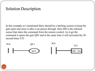
- 1. Solution Description In this example as I mentioned there should be a latching system to keep the gate open and close it after a car passes through. Here I00 is the infrared sensor that takes the command from the remote control. As it get the command it opens the gate Q01 and at the same time it will activated the 20 second timer T33 I0.0 Q0.1 SET 101 I0.0 T33 2000 10ms
- 2. Solution Description Continued After 20 second the timer activate the switch I01 which will reset the output Q01, in other words it will close the gate. But this example does not finish here. A sensor is required to keep the gate open if a car is still in the gate way. So an other infrared sensor I02 is used here to keep the gate open and it is connected to Q01. I0.1 Q0.1 Reset T33 102 M0.1 I0.2 Q0.1
- 3. Example four Automatic water sprinkler system of a garden This example is based on Automatic water sprinkler system of a garden. It delivers water to grass, flowers and trees. Watering of whole garden depends upon humidity and temperature conditions which are adjustable. 103
- 5. Example Continued This example is one of the most complicated examples in this presentation. Here the water sprinkler system (Q0.0) starts to work when either temperature sensor(I0.0) or humidity sensor (I0.1) send a signal to it. In this scenario grass will be water first (water the grass Q0.1) fro 4 second (it is assumed very small for simplicity) and then flowers will be water (water the flowers Q0.2) for 10 second and at last trees will be watered (water the trees Q0.3) for 18 seconds. Since it is required to avoid pressure drop in the water line ,each section is separated and here the order to water this garden is given: First grass, second flowers and third trees. 105
- 6. Example Continued Here you can see that either temperature sensor I0.0 or humidity sensor I0.1 can turn on the sprinkler system (Q0.0). If the humidity or temperature falls below a specific point the system will start working. 106
- 8. Example Continued In this Example it is needed to water the grass for 4 seconds. Since the increment is 10 ms, it is written 400ms in the timer. The input is assume to be the Q0.0 which was the switch for sprinkler system. Here it is assumed that if the sprinkler is on, the output Q0.1 will also become on and it will remain on for 4 seconds. If you take a look at the ladder diagram you will see that the input Q0.0 turn the timer on and it will count 4 seconds until it breaks the second line. 108
- 9. 109
- 10. Example Continued Since the input switch Q0.0 turn on all the timers in this ladder diagram at the same time it is required to add the time for watering of each section with the time elapsed in the previous sequence. For example although it is required to water the flowers for only 10 second but in the timer it is written 1400ms with the increment 10 ms which will eventually be equal to 14 second. Now if you subtract 14 seconds from 4 second (the time required for the first section) you will get the required time which is 10 seconds. There is one more important parameter here. In the ladder diagram it is written if the first section is done start the second section. You can see this in the second line of the ladder diagram. The output here is Q0.2 which is assumed for watering flowers. 110