
Recomendados
Más contenido relacionado
La actualidad más candente
La actualidad más candente (20)
Destacado
Destacado (20)
Similar a 6161103 6.1 simple trusses
Similar a 6161103 6.1 simple trusses (20)
Más de etcenterrbru
Más de etcenterrbru (20)
Último
Último (20)
6161103 6.1 simple trusses
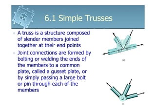
- 1. 6.1 Simple Trusses6.1 Simple Trusses A truss is a structure composed of slender members joined together at their end points Joint connections are formed byJoint connections are formed by bolting or welding the ends of the members to a common plate, called a gusset plate, or by simply passing a large bolt or pin through each of the members
- 2. 6.1 Simple Trusses6.1 Simple Trusses Planar Trusses Planar trusses lie on a single plane and are used to support roofs and bridges The truss ABCD shows a typical roof-supporting truss The truss ABCD shows a typical roof-supporting truss Roof load is transmitted to the truss at joints by means of a series of purlins, such as DD’
- 3. 6.1 Simple Trusses6.1 Simple Trusses Planar Trusses The analysis of the forces developed in the truss members is 2Dthe truss members is 2D
- 4. 6.1 Simple Trusses6.1 Simple Trusses Planar Trusses For a bridge, the load on the deck is first transmitted to the stringers, then to the floor beams, and finally to the joints B, C and D of the two supporting trussestwo supporting trusses Like the roof truss, the bridge truss loading is also coplanar
- 5. 6.1 Simple Trusses6.1 Simple Trusses Planar Trusses When bridge or roof trusses extend over large distances, a rocker or roller is commonly used for supporting one end, Eg: joint E This type of support allows freedom forThis type of support allows freedom for expansion or contraction of the members due to temperature or application of loads
- 6. 6.1 Simple Trusses6.1 Simple Trusses Assumptions for Design 1. “All loadings are applied at the joint” Assumption true for most applications of bridge and roof trussesand roof trusses Weight of the members neglected since forces supported by the members are large in comparison If member’s weight is considered, apply it as a vertical force, half of the magnitude applied at each end of the member
- 7. 6.1 Simple Trusses6.1 Simple Trusses Assumptions for Design 2. “The members are joined together by smooth pins” Assumption true when bolted orAssumption true when bolted or welded joints are used, provided the center lines of the joining members are concurrent
- 8. 6.1 Simple Trusses6.1 Simple Trusses Assumptions for Design Each truss member acts as a two force member, therefore the forces at the ends must bethe forces at the ends must be directed along the axis of the member If the force tends to elongate the member, it is a tensile force If the force tends to shorten the member, it is a compressive force
- 9. 6.1 Simple Trusses6.1 Simple Trusses Assumptions for Design Important to state the nature of the force in the actual design of a truss – tensile ordesign of a truss – tensile or compressive Compression members must be made thicker than tensile member to account for the buckling or column effect during compression
- 10. 6.1 Simple Trusses6.1 Simple Trusses Simple Truss To prevent collapse, the form of a truss must be rigid The four bar shape ABCDThe four bar shape ABCD will collapse unless a diagonal member AC is added for support The simplest form that is rigid or stable is a triangle
- 11. 6.1 Simple Trusses6.1 Simple Trusses Simple Truss A simple truss is constructed starting with a basic triangulara basic triangular element such as ABC and connecting two members (AD and BD) to form an additional element