Measures of Dispersion and Variability: Range, QD, AD and SD
Lect.9 centifugal pump ppt. 2021.pdf
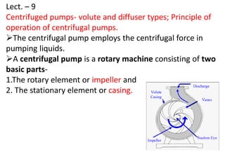
1. Lect. – 9
Centrifuged pumps- volute and diffuser types; Principle of
operation of centrifugal pumps.
The centrifugal pump employs the centrifugal force in
pumping liquids.
A centrifugal pump is a rotary machine consisting of two
basic parts-
1.The rotary element or impeller and
2. The stationary element or casing.
2. The impeller is a wheel or disc mounted on the drive shaft
and provided with number of vanes.
The casing, called the volute (curve funnel), is in the form
of a spiral with a cross sectional area increasing towards the
discharge opening.
3. Centrifugal pump directly driven by motor
Centrifugal pumps are commonly used to move
liquids through piping. Centrifugal pumps are
used for large discharge through smaller heads.
5. Pump Classification
1. Type of energy
conversion
(a) Volute and (b) Diffuser or turbine
2. Number of stages (a) Single- stage and (b) Multi- stage
3 Impeller types (a) Open (b) Semi open (c) closed and
(d) Non clog.
4. Type of suction
inlet
(a)Single suction and (b) Double
suction
5. Axis of rotation (a) Horizontal and (b) Vertical
6. Method of drive (a) Direct- connected
(b) Belt driven or chain driven
6. Volute type pump
• It is most commonly used pump.
• The volute type pump has a casing
made in the form of a spiral or volute
(curve funnel).
• The volute casing starts with a small
cross sectional area near the impeller
periphery and increases gradually to
the pump discharge.
• The casing is proportioned to reduce
gradually the velocity of the liquid as it
flows from the impeller to the
discharge, thus changing the velocity
head into pressure head.
7. Diffuser or Turbine
pump type pump
• It has stationary diffusion vanes
surrounding the impeller
periphery.
• The diffuser vanes have small
openings near the impeller and
enlarge gradually to their outer
diameter.
• A major part of conversion of
velocity into pressure head
takes place between the
diffuser vanes, before the
water enters the volute.
8. • The pump casing may be either circular or spiral
type.
• The efficiency of diffuser type pumps is slightly
higher than volute type pumps.
• The diffuser type pumps are not common except in
large high pressure pumps.
• Conventionally, the diffusers are applied to multi-
stage pumps.
Circular casing Spiral casing
9. The choice between volute and turbine type pump:
• The volute type pump is preferred for large capacity
low head conditions Turbine pumps are used for high
head conditions.
• Turbine pumps are most popular in deep tube wells.
10. The fluid enters the pump impeller along or near to the
rotating axis and is accelerated by the impeller, flowing
radialy outward into a diffuser or volute chamber
(casing), from where it exits into the downstream
piping.
The purpose of centrifugal pump is to convert energy
of a prime mover (a electric motor or turbine) first into
velocity or kinetic energy and then into pressure energy
of a fluid that is being pumped.
Principle of operation of centrifugal pumps
11. The energy changes occur by virtue of two main
parts of the pump, the impeller and the volute or
diffuser.
The impeller is the rotating part that converts
driver energy into the kinetic energy.
The volute or diffuser is the stationary part that
converts the kinetic energy into pressure energy.
The centrifugal pump will not operate until the
casing is entirely full of water or primed.
Note: All of the forms of energy involved in a
liquid flow system are expressed in terms of
head.
12. Conversion of Kinetic Energy to Pressure Energy
• The energy created by the centrifugal force is kinetic
energy. The amount of energy given to the liquid is
proportional to the velocity at the edge or vane tip of the
impeller.
• The faster the impeller revolves or the bigger the impeller
is, then the higher will be the velocity of the liquid at the
vane tip and the greater the energy imparted to the liquid.
• This kinetic energy of a liquid coming out of an
impeller is harnessed by creating a resistance to the
flow. The first resistance is created by the pump volute
(casing) that catches the liquid and slows it down.
H =
Where H = Total head developed in m.
V = Velocity at periphery of impeller m/sec
g = Acceleration due to gravity m/sec2
Velocity is proportional to impeller diameter
and its rpm .
14. (ii) Shaft
The basic purpose of a centrifugal pump shaft is to
transmit the torques encountered when starting and
during operation while supporting the impeller and
other rotating parts.
15. Stationary components
(i)Casing
• Casings are generally of two types: volute and circular. The
impellers are fitted inside the casings.
• A volute is a curved funnel increasing in area towards the
discharge port.
• Circular casing have stationary diffusion vanes surrounding
the impeller periphery that convert velocity energy to
pressure energy.
• Volute casings build a higher head; circular casings are
used for low head and high capacity.
16. ii) Suction and Discharge Nozzle
• The suction and discharge nozzles are part of
the casings itself.
• The suction nozzle is located at the end of,
and concentric to, the shaft while the
discharge nozzle is located at the top of the
case perpendicular to the shaft.
17. (iii) Stuffing box and seal chamber
• Where the shaft leaves the casing there is a gland and
stuffing box to prevent leakage. If the sealing is achieved
by means of a mechanical seal, the chamber is referred
as a Seal Chamber.
• Both have the primary function of protecting the pump
against leakage at the point where the shaft passes out
through the pump pressure casing.
18. Gland
• The gland is a very important part of the seal chamber or
the stuffing box. It gives the packings or the mechanical
seal the desired fit on the shaft sleeve. It can be easily
adjusted in axial direction.
Bearing housing
• The bearing housing encloses the bearings mounted on
the shaft.
• The bearings keep the shaft or rotor in correct alignment
with the stationary parts under the action of radial and
transverse loads.
19. Priming
• Most centrifugal pumps are not self-
priming. In other words, the pump casing
must be filled with liquid before the
pump is started, or the pump will not be
able to function.
20. • Performance Characteristics Curves of the
Pumps
A pump's performance is shown in its
characteristics performance curve where its
capacity i.e. flow rate is plotted against its
developed head.
Flow rate
It is usual to plot
head, power and
efficiency
against capacity
at a constant
speed.
21. • The pump performance curve also shows its
efficiency , required input power (in BHP),
speed (in RPM), and other information such as
pump size and type, impeller size, etc.
• This curve is plotted for a constant speed
(rpm) and a given impeller diameter (or series
of diameters).
22. Vertical centrifugal pumps
• Vertical centrifugal pumps are also referred to
as cantilever pumps.
• They utilize a unique shaft and bearing
support configuration that allows the volute
to hang in the sump while the bearings are
outside of the sump.
• This style of pump uses no stuffing box to seal
the shaft but instead utilizes a "throttle
Bushing".