SlideShare una empresa de Scribd logo
1 de 237
Descargar para leer sin conexión
ENGINE — 1UZ–FE ENGINE                                                 81


                                                 ENGINE

1UZ–FE ENGINE
F DESCRIPTION
  The 1UZ–FE engine is a V–8, 4.0–liter, 32–valve DOHC engine designed exclusively for the luxury LS400 sedan.
  Incorporating the state–of–the–art technology, this engine implements high–speed performance and utility at a high
  level providing an exciting feeling of a very smooth acceleration response to the pedal operation. With thorough
  analysis, design and precisely controlled manufacturing, major component parts have been improved to achieve very
  low vibration and noise level.
  The engine operation is accurately–controlled by the ECU (Electronic Control Unit) and maintains peak performance
  and efficiency at all times.
82                                         ENGINE — 1UZ–FE ENGINE


F ENGINE SPECIFICATIONS AND PERFORMANCE CURVE

                                      Engine
                                                                       1UZ–FE
                                                                       1UZ FE
Item
No. of Cyls. & Arrangement                                      8–Cylinder, V Type
Valve Mechanism                                          32–Valve, DOHC, Belt & Gear Drive
Combustion Chamber                                                 Pentroof Type
Manifolds                                                             Cross–flow
Displacement                      cu. in. (cc)                       242.1 (3,969)
Bore x Stroke                       in. (mm)                  3.44 x 3.25 (87.5 x 82.5)
Compression Ratio                                                      10.0 : 1
Firing Order                                                     1–8–4–3–6–5–7–2
Max. Output (SAE–NET)                                           250 HP @ 5,600 rpm
Max. Torque (SAE–NET)                                          260 ft.lbs @ 4,400 rpm
Fuel Octane Number (RON)                                                  96
Oil Grade*                                                        API SG, EC–II

  *    Refer to the next page for detail.
ENGINE — 1UZ–FE ENGINE                                                     83


*NOTE: Engine oil selection
          Use API (American Petroleum Institute) grade SG, Energy–Conserving II multigrade engine oil.
          Recommended viscosity is as follows, with SAE 5W–30 being the preferred engine oil for the 1UZ–FE
          engine.

                                   DRecommended Viscosity (SAE)A


   A label is added to the oil filler cap and some oil containers to help you select the oil you should use.
   The top portion of the label shows the oil quality by API designations such as SG. The center portion of the label shows
   the SAE viscosity grade, such as SAE 5W–30.
   “Energy–Conserving II” shown in the lower portion, indicates that the oil has fuel–saving capabilities.

                                   DOil Identification LabelA


   Oils marked “Energy–Conserving II” will have higher fuel–saving capabilities than oils marked
   “Energy–Conserving.”
84                                          ENGINE — 1UZ–FE ENGINE


F FEATURES OF 1UZ–FE ENGINE
      Features of the 1UZ–FE engine are shown in the following list:

               Features                                                    Contents
                                     S Compact DOHC, 32–valve, center–firing and high compression ratio
                                         combustion chamber implements a high combustion efficiency.
High Performance                     S ECU–controlled precise engine operation.
                                     S Reduced intake and exhaust losses resulting from large–diameter intake duct,
                                         air flow meter, dual exhaust system, etc.
                               S Reduced cylinder head size by the adoption of a scissors gear mechanism.
Lightweight and Compact Design S Cylinder block and oil pan made of aluminum alloy.
                               S Compact, lightweight accessory drive system by means of serpentine, single
                                         belt and bracketless accessory installation.
                                     S   Use of an aluminum oil pan having an integral stiffener.
                                     S   Aluminum engine mount brackets and liquid–filled compound engine mounts.
Low Noise and Vibration              S   Silent start type three–stage temperature–controlled auto–coupling fan.
                                     S   Rigid and accurately balanced crankshaft assembly.
                                     S   Auto tensioners for timing belt and V–ribbed belt.
                                     S Outer shim type valve lifter.
Serviceability                       S Auto tensioners for timing belt and V–ribbed belt.
                                     S Engine oil level sensor.
                                     S Thin cast–iron liner press–fit in aluminum cylinder block.
High Reliability                     S Highly durable timing belt and auto tensioner.
                                     S Plastic region tightening bolts in major parts (cylinder head bolts, crankshaft
                                         bearing cap bolts, connecting rod cap bolts).
ENGINE — 1UZ–FE ENGINE                                                    85


F ENGINE
1. Cylinder Head
  S The cylinder head is made of aluminum and has intake and exhaust ports in a cross–flow arrangement. The intake
     ports are on the inside and the exhaust ports on the outside of the left and right banks respectively.

  S The cylinder heads are compact even for a DOHC engine. The pitch of the intake and exhaust camshafts is
     shortened and the valve angle is narrowed to 21_33′.

  S The left and right banks of cylinder heads are common in configuration.

      NOTICE
  When the cylinder heads are disassembled for servicing, be sure to assemble each cylinder head to the correct right
  or left bank. The camshaft may seize if they are assembled incorrectly.


  S Pentroof type combustion chamber with four valves is used.
  S The squish area guides the air–fuel mixture to the center of the combustion chamber to increase the combustion
     speed and thus maintain a stable engine operation.


  S Plastic region tightening bolts, having a good axial tension stability, are used for securing the cylinder heads to
     the block.


NOTE:    When reusing the cylinder head bolts, make sure the diameter at the thread is not less than 0.378 in. (9.6 mm).
         It will be necessary to replace them with new ones if the diameter is less than specification.
86                                            ENGINE — 1UZ–FE ENGINE


2. Cylinder Block
     S The cylinder block has a bank angle of 90_, a bank offset of 0.827 in. (21 mm) and a bore pitch of 4.15 in. (105.5
        mm), resulting in a compact block in its length and width even for its displacement.

     S Lightweight aluminum alloy is used for the cylinder block.
     S A thin cast–iron liner is press–fit inside the cylinder to ensure an added reliability.
         NOTICE
     Never attempt to machine the cylinder because it has a thin 0.08 in. (2 mm) liner inside.


     S Part of the volute chamber of the water pump and the water by–pass passage are incorporated into the cylinder
        block to shorten the engine length.

     S Installation bosses of the two knock sensors are located on the inner side of left and right banks.
     S The plastic region tightening bolts are used for the crankshaft bearing caps.

NOTE:       When reusing the crankshaft bearing cap bolts, make sure the diameter at the thread is not less than 0.291
            in. (7.4 mm). It will be necessary to replace them with new ones if the diameter is less than specification.

     S The starter is located inside the V–bank.
     S To install a local engine block heater, first remove the cover plate shown in the “A” view drawing below.
ENGINE — 1UZ–FE ENGINE                                             87


 NOTICE
When fitting the crankshaft bearing cap, always tighten   first and   next in order to obtain roundness of the
bearing.
88                                          ENGINE — 1UZ–FE ENGINE


3. Piston
     S Steel struts are used to control thermal
        expansion.

     S The skirt of each piston is striation finished
        (finely grooved) for maintaining          proper
        lubrication and reducing friction loss.

     S The piston has a weight–adjusting boss to
        minimize fluctuation of weight among pistons
        and balance the engine assembly.

     S Piston pins are the full–floating type and are
        held in place with snap rings.


4. Piston Ring
     S Each surface of the compression ring No. 1 and
        the oil ring side rail is nitrified to prevent an
        increase of oil consumption and blow–by gas as
        the time elapses.
ENGINE — 1UZ–FE ENGINE   89


5. Connecting Rod

  S The sintered and forged connecting rod is very
     rigid and has little weight fluctuation.

  S A weight–adjusting boss is provided at the big
     end to reduce fluctuation of weight and balance
     the engine assembly.

  S The connecting rod cap is held by plastic region
     tightening bolts.

NOTE:    When reusing the connecting rod cap bolts,
         if the diameter at the thread is less than
         0.275 in. (7.0 mm), it is necessary to
         replace them with new ones.

  S The connecting rods for the right and left banks
     are placed in opposite directions with the outer
     marks facing the crankshaft.
90                                          ENGINE — 1UZ–FE ENGINE


6. Crankshaft and Crankshaft Bearings
     S A forged crankshaft with five main journals, four connecting rod pins and eight balance weights is used.
     S Connecting rod pins and journals are induction–hardened to ensure an added reliability.


     S Bearings are made of kelmet.


     S Crankshaft bearings are selected carefully according to the measured diameters of the crank journal and cylinder
        block journal holes.

NOTE:       The diameter of the crank journal and the cylinder block journal hole is indicated at the places shown below.
ENGINE — 1UZ–FE ENGINE                                               91


NOTE:    Numbers of the crankshaft and pistons are shown on the right side.


  Crankshaft angles and engine strokes (intake, compression, combustion and exhaust) are shown in the table below.
  The firing order is 1–8–4–3–6–5–7–2.
92                                         ENGINE — 1UZ–FE ENGINE


F VALVE MECHANISM
1. General
     S Each cylinder has two intake valves and two exhaust valves.
     S The valves are directly opened and closed by four camshafts.
     S The intake camshafts are driven by a timing belt, while the exhaust camshafts are driven through gears on the
        intake camshafts.

     S Use of outer shim type valve lifters makes it easy to adjust the valve clearance without removing the camshaft.
ENGINE — 1UZ–FE ENGINE                                                   93


2. Camshafts
 S The exhaust camshafts are driven by gears on the intake camshafts. The scissors gear mechanism has been used
    on the exhaust camshaft to control backlash and reduce gear noise.

 S The camshaft journals and camshaft driven gear are lubricated by oil supplied to an oil passage in the center of
    the camshaft. Supply of oil from the cylinder heads to the camshafts is continuous, to prevent fluctuations in the
    oil pressure.

 S The cast iron camshafts are used. The cam nose is chill treated.
 S “T” type oil seals are used.


  NOTICE
 Be sure to follow the disassembly and reassembling procedures as directed in the Repair Manual to avoid possibility
 of damaging the cylinder head or camshaft timing gears (drive, driven and subgears).
94                                      ENGINE — 1UZ–FE ENGINE

—REFERENCE—
Scissors Gear Mechanism
To prevent the tooth surfaces of gears from seizing or being damaged when the gears are engaged, they are
designed to have backlash. However, backlash generates noise when changes in torque occur. The scissors gear
mechanism is one means of preventing this noise. The scissors gear mechanism uses a subgear with the same
number of teeth as the drive gear and is attached to the gear on the driven side. Through the reaction force of the
scissors spring, these two gears act to pinch the drive gear, reducing backlash to zero and eliminating gear noise.
ENGINE — 1UZ–FE ENGINE   95


3. Valve Lifter and Valve Adjusting Shims
  S Aluminum alloy valve lifters are used.
  S The valve adjusting shims used are of the outer
     shim type and are located on top of the valve
     lifters. It is not necessary to remove the
     camshafts in order to replace the shims when the
     valve clearance is adjusted.

NOTE:    (Method for replacing valve shims)
         Push down the valve lifter using an SST
         (Special Service Tool) to make a gap
         between the camshaft and the valve lifter.
         Direct compressed air from an air gun to the
         service hole in the valve adjusting shim to
         float the shim and remove it using a
         magnetic finger. Be sure to direct the air
         gun carefully so that you do not blow the
         shim away.


4. Timing Pulleys and Belt


  S An auto–tensioner is made up of a spring and oil
     damper, and maintains proper timing belt
     tension at all times. The auto–tensioner
     suppresses noise generated by the timing belt.

  S The timing belt has high heat resistance and
     durability.

  S The tooth profile of the timing belt is shown at
     the right. This design ensures a quiet operation
     and high–load transmission.
96                                           ENGINE — 1UZ–FE ENGINE


F LUBRICATION SYSTEM
1. General
     S The lubrication is fully pressurized and all oil passes through an oil filter.
     S The oil pump is a trochoid gear type and is directly driven by the crankshaft.
ENGINE — 1UZ–FE ENGINE   97


2. Oil Pan
 S The oil pan is made up of two pieces. No. 1 oil
    pan is made of aluminum alloy and No. 2 oil pan
    is made of steel.

 S The upper oil pan section is secured to the
    cylinder block and the torque converter
    housing, increasing rigidity.

 S The baffle plate controls the oil flow between
    the two oil pans when the vehicle is turning or
    is running along rough roads, etc.


 S An oil lever sensor is provided in the oil pan for
    efficient servicing.
    When the oil level falls below the specified
    level, the oil level sensor causes the low engine
    oil level warning light inside the combination
    meter to light up.
98                                          ENGINE — 1UZ–FE ENGINE


F COOLING SYSTEM
1. Cooling Circuit
     S The cooling system is a pressurized, forced–circulation type.
     S A thermostat, having a bypass valve, is located on the water pump inlet side of the cooling circuit. As the coolant
        temperature rises, the thermostat opens and the bypass valve closes, so the system maintains suitable temperature
        distribution in the cylinder head.

     S A gauge coolant temperature sender, coolant temperature sensor, start injector time switch for the EFI (Electronic
        Fuel Injection) and BVSV (Bimetal Vacuum Switching Valve) for charcoal canister control are fitted to the front
        water joint.

     S The rear water joint has bypass outlet ports for heating the throttle body, cooling the EGR valve and hot water
        for the heater.
ENGINE — 1UZ–FE ENGINE                                                    99


2. Water Pump
 S The water pump has two volute chambers, and
      circulates coolant uniformly to the left and right
      banks of the cylinder block.

 S The water pump is driven by the back of the
      timing belt.

 S The rotor is made of resin.


3. Reservoir Tank
 S A pressurized valve is fitted to the reservoir.
 S A coolant level sensor is provided for efficient servicing.
      When the coolant level falls below the specified level, the coolant level sensor causes the low engine coolant level
      warning light inside the combination meter to light up.


      CAUTIONS
 1.   Never remove the cap while it is hot because the reservoir is also pressurized.
 2.   Engine coolant is replenished from the reservoir. To do so, first loosen the plug at the top of the inlet housing
      (shown on Page 98) to bleed air out of the cooling system. Be sure that the system is filled with coolant
      completely.
100                                         ENGINE — 1UZ–FE ENGINE


4. Coupling Fan
  S A three stage temperature–controlled auto
      coupling fan is used.
      The speed of the coupling fan changes in three
      stages based on the temperature of the air
      passing through the radiator.
      This keeps the fan speed low when the
      temperature is low, improving warm–up
      performance and reducing fan noise.
      The fan speed is high when the engine
      temperature is high, improving the cooling
      performance.
      Since part of the oil in the coupling fan is stored
      in the back storage chamber, the amount of oil
      in the operating chamber decreases at engine
      start. Oil resistance and the fan speed are
      reduced as a result immediately after engine
      start.
      The oil stored in the back storage chamber
      gradually flows into the operating chamber as
      the coupling fan keeps revolving. It eventually
      flows entirely into the operating chamber.
ENGINE — 1UZ–FE ENGINE                                                  101


F INTAKE AND EXHAUST SYSTEM
1. Air Cleaner
  The air cleaner case and cap are made of resin and have a large filtering capacity for the large engine displacement.
  The air cleaner element is a low air resistance type and allows the air to pass through it very smoothly.


2. Intake Air Resonator
  S A resonator is used to reduce the intake air noise.
  S The resonator is made of resin. The air passage and resonator chamber are formed separately. The resonator
     chamber is of the dual mode type and is separated by a partition.
102                                        ENGINE — 1UZ–FE ENGINE


3. Intake Air Chamber
  S The EGR and ISC (Idle Speed Control) passages
      are attached to the intake air chamber.

  S The start injector is located at the center of the
      intake air chamber so that fuel is distributed
      evenly to all cylinders.


4. Intake Manifold
  S Ports are crossed to increase the port length and
      inertia effects of the intake air.
ENGINE — 1UZ–FE ENGINE                                                   103


5. Exhaust Manifold
 S Both exhaust manifolds are made of stainless steel.
 S The exhaust manifolds are covered with heat insulators to protect the surrounding parts from exhaust heat.


6. Exhaust Pipe
 S The stainless steel exhaust pipe consists of three sections; the front, center and tail. The center section is single
     pipe while the front and tail are dual pipes to reduce exhaust resistance.

 S The catalyst converters (start and main) are of the monolithic type three–way catalysts.
 S The main catalyst converter is newly developed and has a high performance.
 S Large mufflers (main and sub) effectively reduce noise and exhaust pressure from the large capacity engine.


 *   Applicable only to the California specification vehicles. Refer to page 161 for detail.
104                                         ENGINE — 1UZ–FE ENGINE


F SERPENTINE BELT DRIVE SYSTEM
   S The serpentine belt drive system drives accessory components with a single V–ribbed belt. It reduces the overall
        engine length, weight and number of engine parts.

   S An automatic tensioner eliminates the need for tension adjustment.


   S The arm is pushed by the tension spring in a
        clockwise rotation direction always centering
        around “Z”.
        The pulley’s center of rotation is bolted to the
        arm.
        For this reason, when the belt stretches with
        time, the pulley center of rotation rotates to the
        right in an arc around “Z” with the arm. Thus the
        belt tension is always maintained appropriately.

       NOTICE
       S Check the indicator mark. If it is outside the
          operation range, replace the belt.

       S When a new belt is installed, the graduations
          must be in the area indicated by “A” in the
          picture.
ENGINE — 1UZ–FE ENGINE                                              105


F ENGINE MOUNTING
1. General
  S Liquid–filled compound engine mounts are fitted on both sides of the engine to reduce vibration and noise at all
     speeds.

  S The aluminum engine mounting brackets reduce vibration and noise and minimize the total engine weight.


2. Liquid–Filled Compound Engine Mount
  The engine mount combines rubber with liquid
  filled chambers.
  The fluid flows between upper and lower chambers
  through an orifice.
  In addition to vibrations being absorbed by the
  rubber mounting, low frequency vibration is
  absorbed by the fluid flowing through the orifice.
  Also, by decreasing the elasticity of the rubber, the
  dynamic spring constant has been reduced,
  providing greater noise reduction in the case of high
  frequency vibrations.
106                                       ENGINE — 1UZ–FE ENGINE

F STARTING SYSTEM
1. Starter
  S The starter output is 2.0 KW and is located
      inside the V–bank of the cylinder block.


F CHARGING SYSTEM
1. Alternator
  S The IC regulated alternator has a large output of
      1200 watts to produce enough electricity for the
      electric load.

  S The alternator is fitted directly (without
      brackets) to the cylinder block.
ENGINE — 1UZ–FE ENGINE                                                     107


F ENGINE MOUNTING
1. General
  Engine control system uses an ECU (Electronic Control Unit) with a built–in microprocessor. Stored inside the ECU
  is the data for fuel injection duration, ignition timing and idling speed, etc. which are matched with the various engine
  conditions as well as programs for calculation. The ECU utilizes these data and signals from the various sensors in
  the vehicle and makes calculations with the stored programs to determine fuel injection duration, ignition timing and
  idling speed, etc., and outputs control signals to the respective actuators which control operation.
  The engine ECU and transmission ECU are integrated into one and the ECU is called the engine and transmission
  ECU. The engine control system for the 1UZ–FE engine has the following functions:
 EFI (Electronic Fuel Injection)
  The ECU determines the fuel injection duration according to intake air volume, engine speed, coolant temperature
  and other signals and sends control signals to the fuel injectors. Also, this fuel injection duration is the basis for
  deciding the fuel injection timing. The fuel injection system in the 1UZ–FE engine is a four group injection system
  which injects fuel simultaneously into two cylinders once every two engine revolutions.
 ESA (Electronic Spark Advance)
  The ECU determines the amount of ignition advance over the initial set timing of the distributor by the intake air
  volume, engine speed, coolant temperature and other signal and sends control signals to the igniters. Also, based on
  signals from the knock sensors, the ECU controls the ignition timing at the optimum in accordance with the gasoline’s
  octane value.
 ISC (Idle Speed Control)
  By means of engine speed signals and coolant temperature signals, the ECU sends control signals to the ISC valve
  so that the actual idling speed becomes the same as the target idling speed stored in the ECU. Also, while the engine
  is warming up, the ECU, based on coolant temperature signals, sends controls signals to the ISC value to control
  engine speed to fast idle.
 EGR (Exhaust Gas Recirculation) CUT CONTROL
  The ECU sends signals to the EGR VSV to cut the EGR based on coolant temperature, engine speed, neutral start
  switch or intake air volume signals. This system maintains drivability at low coolant temperature, under light or heavy
  load conditions, or at high engine speed, etc.
 FUEL PRESSURE CONTROL
  The ECU sends signals to the pressure regulator VSV based on coolant temperature, intake air temperature, vehicle
  speed and engine start signals, and increases the fuel pressure. This system maintains restartability and idling stability
  when the engine is hot.
 FUEL PUMP SPEED CONTROL
  The ECU, based on fuel injection duration, sends control signals to the fuel pump control relay to control the fuel
  pump speed. That is, when the engine requires a large volume of fuel, the fuel pump turns at high speeds and when
  only a small volume of fuel is required, the pump turns at low speeds.
108                                       ENGINE — 1UZ–FE ENGINE

OXYGEN SENSOR HEATER CONTROL
  Based on the intake air volume, engine start and coolant temperature signals, the ECU sends control signals to the
  oxygen sensor heater. This system maintains the oxygen sensor at the appropriate temperature in order to improve
  the detecting accuracy of oxygen concentration in the exhaust gas.
AIR CONDITIONER CONTROL
  Based on the air conditioner switch signal from the air conditioner ECU, the ECU sends control signals to the
  magnetic clutch of the air conditioner compressor. This system, the magnetic clutch operation, is delayed for a
  predetermined period after the air conditioner switch is turned on.
DIAGNOSIS
  The ECU is constantly monitoring signals from each sensor. If a malfunction occurs with the signals, the CHECK
  ENGINE lamp on the combination meter lights up and informs the driver of the malfunction.
  The content of the malfunction is stored in code in the ECU and when the TE1 and E1 terminals in the check connector
  or TDCL are connected, the ECU outputs the trouble code by flashing the CHECK ENGINE lamp.
FAIL–SAFE
  If the ECU judges from the signals from each sensor that there is a malfunction, it continues the engine operation using
  its own data or it stops the engine.
ENGINE — 1UZ–FE ENGINE                                              109


2. Construction
 The engine control system can be broadly divided into three groups: the ECU, the sensor and the actuators.


 1    Applicable only to California specification vehicles.
 *2   Applicable only to vehicles equipped with the optional TRAC (Traction Control) system
110                                    ENGINE — 1UZ–FE ENGINE


3. Summary of Engine Control System
  The following list summarizes each system and control composing engine control system of the 1UZ–FE engine and
  types of the related sensors, ECU and others.


 *1: Applicable only to California specification vehicles.
 *2: Applicable only to vehicles equipped with the optional TRAC (Traction Control) system
ENGINE — 1UZ–FE ENGINE                                 111


4. Engine Control System Diagram


 *1: Applicable only to California specification vehicles.
 *2: Applicable only to vehicles equipped with the optional TRAC (Traction Control) system
112                       ENGINE — 1UZ–FE ENGINE


5. Arrangement of Engine Control System Components
ENGINE — 1UZ–FE ENGINE                                                     113


6. EFI (Electronic Fuel Injection)
 The EFI system consists of the following three major systems:
 1) Fuel System
 2) Air Induction System
 3) Electronic Control System


Fuel System
  1) General
     Fuel is pumped under pressure by the electric fuel pump from the fuel tank, through the fuel filter, to the injectors
     and the cold start injector.
     The pressure regulator controls the amount of fuel being returned to the fuel tank through the return pipe, thus
     adjusting the pressure of fuel to the injectors.
     The pulsation damper absorbs the minute fluctuations in fuel pressure due to injection of fuel.
     The injectors inject fuel into the intake port in accordance with injection duration signals from the ECU.
     The cold start injector injects fuel into the air intake chamber when the coolant temperature is low, improving
     startability in cold weather.
114                                       ENGINE — 1UZ–FE ENGINE


  2) Fuel Pump
       An in–tank type fuel pump is provided inside
       the fuel tank.
       A turbine pump, with little discharge pulsation
       of the fuel in the pump, is used.
       This pump consists of the motor portion and the
       pump portion, with a check valve, relief valve
       and filter also incorporated into the unit.

      a. Turbine Pump

        The turbine pump consists of the impeller,
        which is driven by the motor, and the casing
        and pump cover, which compose the pump
        unit. When the motor turns, the impeller turn
        along with it.
        Blades on the outer circumference of the
        impeller pull fuel from the inlet port to the
        outlet port.
        Fuel discharged from the outlet port passes
        through the motor portion and is discharged
        from the pump through the check valve.


      b. Relief Valve

        The relief valve open when the discharge side
        pressure reaches 71.1!92.3 lb/in.2 (5.0!6.5
        kg/cm 2) and the high pressure fuel is returned
        directly to the fuel tank.
        The relief valve prevents the fuel pressure
        from rising beyond that level.

      c. Residual Pressure Check Valve

        The check valve closes when the fuel pumps
        stops.
        The residual pressure check valve and
        pressure regulator both work to maintain
        residual pressure in the fuel line when the
        engine is stopped, thus easing restartability.
        If there were no residual pressure, vapor lock
        could occur easily at high temperatures,
        making it difficult to restart the engine.


          S The 1UZ–FE engine has a fuel pump speed control (ECU controlled) system which regulates the amount
             of electricity flowing to the fuel pump and thus the amount of fuel delivery according to the engine load.
             See page 149 for detail.
ENGINE — 1UZ–FE ENGINE   115

3) Fuel Filter
   The fuel filter filters out dirt and other foreign
   particles from the fuel. It is installed at the high
   pressure side of the fuel pump.


4) Pulsation Damper
   Fuel pressure is maintained at 41 lb/in.2 (2.9
   kg/cm 2) in relation to the manifold vacuum, by
   the pressure regulator. However, there is a
   slight variation in line pressure due to injection.
   The pulsation damper acts to absorb this
   variation by means of a diaphragm.
116                                         ENGINE — 1UZ–FE ENGINE

  5) Pressure Regulator
      a. Function

        The pressure regulator regulates the fuel
        pressure to the injectors. Fuel injection
        quantity is controlled by the duration of the
        signal applied to the injectors, so that a
        constant pressure must be maintained to the
        injectors. However, as fuel is injected into the
        intake port and manifold vacuum varies, the
        fuel injection quantity will vary slights even if
        the injection signal and fuel pressure are
        constant. Therefore, to acquire an accurate
        injection quantity, the sum of the fuel pressure
        A and intake manifold vacuum B must be
        maintained at 41 lb/in.2 (2.9 kg/cm2).

      b. Operation

        Pressurized fuel from the delivery pipe pushes
        on the diaphragm, opening the valve. Part of
        the fuel flows back to the fuel tank through the
        return pipe. The amount of fuel return depends
        on the extent of the diaphragm spring tension
        and the fuel pressure varies according to the
        return fuel volume.
        Intake manifold vacuum is led to the chamber
        of the diaphragm spring side, weakening the
        diaphragm spring tension, increasing the
        volume of return fuel and lowering the fuel
        pressure. In short, when intake manifold
        vacuum rises (less pressure), fuel pressure
        falls only to the extent of the decrease in
        pressure, so that sum of the fuel pressure A and
        the intake manifold vacuum B is maintained at
        a constant.
        The valve is closed by the spring when the fuel pump stops. As a result, the check valve inside the fuel pump
        and the valve inside the pressure regulator maintain residual pressure inside the fuel line.

         S The 1UZ–FE engine has a fuel pressure control (ECU controlled) system which maintains the fuel pressure
             at higher levels than normal for a predetermined time when the engine is hot when started, maintaining
             the engine startability and the idle stability. See page 150 for detail.
ENGINE — 1UZ–FE ENGINE   117

6) Fuel Injector
   Fuel is injected into the intake port of each
   cylinder in accordance with injection signals
   from the ECU.
   At the tip of the injector, there are two injection
   holes.
   The light and small plunger permits quick
   response to signals from the ECU.
   When a signal from the ECU is received by the
   solenoid coil, the plunger is pulled against
   spring force. Since the valve needle and
   plunger are a single unit, the valve needle is
   also pulled from its seat and fuel is injected.
   Fuel volume is controlled by the duration of the
   signal.
7) Cold Start Injector
   The cold start injector injects fuel into the
   intake air chamber during engine cranking to
   improve startability.
   In starting the engine when the engine coolant
   temperature is 71.6_F (22_C) or lower, the cold
   start injector’s operation time is controlled by
   the start injector time switch.
   However, starting the engine when engine
   coolant temperature is 140_F (60_C) or lower,
   the operation time of the cold start injector is
   controlled by the ECU.
   Thus, the cold start injector is controlled by the
   start injector time switch and the ECU
   simultaneously when the coolant temperature
   is below 71.6_F (22_C).
118                                       ENGINE — 1UZ–FE ENGINE

Air Induction System
  1) General
      Air cleaned by the air cleaner enters the air intake chamber according to the throttle valve opening in the throttle
      body and the engine speed. An optical Karman–Vortex type air flow meter is provided between the air cleaner
      and the throttle body to optically detect the frequency of the Karman–Vortex that is generated when the air passes
      to measure the amount of air being taken into the engine.
      A throttle valve in the throttle body controls the air volume.
      The air regulated by the throttle valve enters the air intake chamber, is distributed to the intake manifold of each
      cylinder and enters the combustion chamber.
      ISC (Idle Speed Control) valve is also provided on the throttle body and directs the intake air bypassing the
      throttle body to the air intake chamber. The amount of air bypassing the throttle body is determined by a signal
      from the ECU to control the idle speed and fast idle speed accordingly.
      The air intake chamber prevents pulsation of the intake air to minimize the adverse affection to the air flow meter.
      This helps to increase accuracy of measurement of the intake air volume. It also prevents intake air interference
      in cylinders.
ENGINE — 1UZ–FE ENGINE                                                    119

2) Construction and Operation of Main Components

 a. Air Flow Meter

   S Description
    An optical Karman–Vortex type air flow
    meter is used.
    This air flow meter measures the intake air
    volume      electrically, enabling precise
    detection. It is made compact and lightweight.
    The simplified construction of the air passage
    also reduces air intake resistance.


   S Principle
    Karman–Vortex Street
    When a cylindrical object (Vortex generating body) is placed in the path of gaseous current, vortices (called
    Karman–Vortex) are generated in the wake of the object. If the Karman–Vortex frequency is f, the air velocity
    V and the diameter of the cylindrical object d, then the following equation can be made:


   S Construction and Operation
    Using the above principle, the air flow meter is fitted with a vortex generator. As air flows past the vortex
    generator, vortices are generated at a frequency proportional to the velocity of the air flow.
    A calculation of the frequency can then determine the amount of air flow.
    The vortices are detected by subjecting the surface of thin metal foil (mirror) to the pressure of the vortices and
    optically detecting the vibrations in the mirror by means of a luminous diode and a photo transistor.
    The intake air volume signal (Ks) is the pulse signal. When the intake air volume is low, this signal has a low
    frequency. When the intake air volume is high, it has a high frequency.
120                                        ENGINE — 1UZ–FE ENGINE


      b. Throttle Body
        The throttle body contains the throttle valve that regulates the amount of intake air, the throttle position sensor
        that detects the throttle valve opening, and the dash pot that reduces the closing speed of the throttle valve.
        The throttle body has the following features:

         S The throttle body contains a throttle valve, sufficiently large in diameter to meet the large engine
            displacement.
         S A linear type throttle position sensor is
            mounted on the throttle valve shaft.
         This sensor detects the throttle valve
         opening angle, converts it to a voltage and
         sends it to the engine and transmission ECU.
         (Refer to the next page for detail.)
         S Engine coolant passes through the
             throttle body to maintain warmth under
             cold weather conditions.

         S When the optional TRAC (Traction Control) is fitted, a sub–throttle actuator, sub–throttle valve and
             sub–throttle position sensor are added to the throttle body.
ENGINE — 1UZ–FE ENGINE                                                   121


S Throttle Position Sensor
The throttle position sensor is mounted on the throttle body. This sensor converts the throttle opening angle into
a voltage and sends it to the ECU as the throttle position signal.
A constant 5V is applied to the Vcc terminal from the ECU. As the contact slides along the resistor in accordance
with the throttle valve opening angle, a voltage is applied to the VTA terminal in proportion to this angle.
When the throttle valve is closed completely, the contact for the IDL signal connects between the IDL and E2
terminals.
Another throttle position sensor for the sub–throttle valve is added to the vehicle with the optional TRAC
(Traction Control). It is the same as the main throttle position sensor in construction and operation.
122                                      ENGINE — 1UZ–FE ENGINE

  Electronic Control System
    1) General
       The ECU incorporates a built–in microprocessor. It controls injection duration precisely based on the data stored
       in its memory and signals from each sensor.
       Also, the ECU, based on this injection duration, controls the ignition timing.
       Further, the fuel injection system is a four group injection system.
       The ECU controls to inject fuel into two cylinders simultaneously once every two engine revolutions.
DFuel Injection TimingA
ENGINE — 1UZ–FE ENGINE   123

2) Construction and Function of Relevant Sensors
 a. Cam Position Sensors and Engine Speed Sensor

   S General
    Revolution of the G signal plate on the
    camshaft and Ne signal plate on the crankshaft
    alters the air gap between the projection of the
    plate and the G pickup coil (or the Ne pickup
    coil). The change in the gap creates an
    electromotive force in the pickup coil. This
    voltage appears as an alternating output since
    it reverses its direction periodically as the
    plate approaches and leaves the pickup coil.


   S Cam Position Sensors (G1 and G2 signals)
    The G1 signal informs the ECU of the standard
    crankshaft angle, which is used to determine
    injection timing and ignition timing in relation
    to TDC of No. 6 cylinder. G2 sensor conveys
    the same information for No. 1 cylinder.
    These sensors are made up of (1) signal plate,
    which is fixed to the camshaft timing pulley
    and turn once for every two rotations of the
    crankshaft, and (2) the two sensors (G1 and G2
    sensors), which are fitted to the distributor
    housing.
    The G1, G2 signal plates are provided with a
    projection which activates the G1 and G2
    sensors once for each rotation of the camshaft,
    generating the wave forms as shown in the
    chart. From these signals, the ECU detects
    when the No. 6 and No. 1 pistons are near their
    TDC.
124                                     ENGINE — 1UZ–FE ENGINE

      S Engine Speed Sensor (Ne signal)
      The Ne signal is used by the ECU to detect the
      actual crankshaft angle and the engine speed.
      The ECU determines the basic injection
      duration and basic ignition advance angle by
      these signals. Ne signals are generated in the
      Ne sensor by the Ne signal plate like the G1
      and G2 signals. The only difference is that the
      signal plate for the Ne signal has 12 teeth.
      Therefore, 12 Ne signals are generated per
      engine rotation.
      From these signals, the ECU detects the
      engine speed as well as each 30_ change in the
      engine crankshaft angle.
ENGINE — 1UZ–FE ENGINE   125

b. Oxygen Sensors
  Four oxygen sensors in total are fitted, one
  each in front of and after the start catalyst
  converters. The one in front of the catalyst
  converter is the main oxygen sensor and after
  the converter is the sub–oxygen sensor. The
  main and sub–oxygen sensors are identical in
  construction and function, except for the fact
  that the main oxygen sensor has a heater.
  The O2 sensor consists of a test tube shaped
  zirconia element with a thin layer of platinum
  coated to both the inside and outside. This
  sensor is fitted to the exhaust manifolds and
  exhaust pipes on both the left and right sides
  to sense oxygen concentration (air–fuel ratio)
  in the exhaust gas. If there is a difference in the
  oxygen concentration on the two sides of the
  zirconia element, an electromotive force is
  generated, or if the temperature of the O2
  sensor becomes high, the platinum acts as a
  catalyst, causing the oxygen in the exhaust gas
  to react with the CO. This decreases the
  oxygen volume in the gas. The zirconia
  element’s electromotive force changes
  suddenly at the boundary near the ideal
  air–fuel ratio.
  Using these properties, exhaust gas is passed
  over the outer surface of the O2 sensor and
  atmospheric air is introduced into the inside of
  the sensor. The sensor accurately detects
  whether the oxygen concentration, that is, the
  air–fuel ratio, is higher (rich) or lower (lean)
  than the ideal air–fuel ratio.
  If the air–fuel is rich, the zirconia element
  generates high voltage (approximately 1V).
  This “rich” signal is sent to the ECU.
  Conversely, if the air–fuel ratio is lean, the
  electromotive force of the O2 sensor is low.
  The ECU increases or decreases the injection
  volume in accordance with these signals.
  A heater is provided in the sensors which are
  fitted to the exhaust manifolds. It heats the
  zirconia element. This heater is controlled by
  the ECU. When the intake air volume is low
  (the exhaust gas temperature is low), current
  flows to the heater, maintaining the sensor
  accuracy.
126                                          ENGINE — 1UZ–FE ENGINE

  3) Functions of the ECU
      a. Determination of Injection Timing
        When the ECU receives the G1 signal from the
        cam position sensor and then the Ne signal
        from the engine speed sensor in this order, it
        determines that the crankshaft angle at No. 6
        cylinder is at 5_ BTDC position.
        When the Ne signal is received immediately
        after the G2 signal, it judges that the crankshaft
        angle at No. 1 cylinder is at 5_ BTDC. The
        ECU accurately calculates the crankshaft
        angle based on G1, G2 and Ne signals and
        determines the injection timing accordingly.

      b. Principle of Fuel Injection Duration Control
        The fuel injection duration is determined by the basic injection duration which is determined by intake air
        volume and the engine speed, plus any compensation based on signals from various sensors. During engine
        starting (cranking), it is determined differently because the amount of intake air is not stable during cranking.
        Once the engine is started, the ECU determines the duration of injection in the following steps:
        Step 1: Determination of Basic Injection Duration
        The ECU selects, from the data stored in its memory, an injection duration that is suitable for the intake air
        volume (detected by the air flow meter) and the engine rpm (detected by the engine speed sensor).
        This injection duration is called the “basic injection duration.”
        Step 2: Determination of Adjusted Duration of Injection
        Under most engine condition, the engine runs smoothly at an air–fuel mixture ratio of approximately 14.7 (this
        is called the “ideal air–fuel ratio”). However, when the engine is still cold, or when an extra load is applied to
        the engine, the air–fuel ratio is reduced to below 14.7 (i.e., it becomes richer). The ECU detects these engine
        conditions by means of the water temp. sensor, throttle position sensor and intake air temp. sensor, etc., and
        corrects the basic injection duration to optimize it for the existing engine conditions.
        Also, even under normal engine conditions, the injection duration is corrected by the signals from the oxygen
        sensors to keep the air–fuel ratio within a narrow range near 14.7. The corrected time is called the “adjusted
        injection duration”.
        Step 3: Determination of Injection Signal Length
        There is a slight delay between the time the ECU sends an injection signal to the injectors and the time the
        injectors actually open.
        This delay becomes longer the more the voltage of the battery drops.
        The ECU compensates for this delay by lengthening the injection signal by a period corresponding to the length
        of the delay.
        This corrects the actual injection period so that it corresponds with that calculated by the ECU.
ENGINE — 1UZ–FE ENGINE                                                    127


c. Starting Injection Control
   During engine starting, it is difficult for the air flow meter to accurately sense the amount of air being taken in
   due to large fluctuations in rpm.
   For this reason, the ECU selects from its memory an injection duration that is suitable for the coolant
   temperature, regardless of intake air volume or engine rpm. It then adds to this an intake air temperature
   correction and a voltage correction, to obtain the injection duration.


                                                                    RELEVANT SIGNALS
                                                                    S   Engine speed (Ne)
                                                                    S   Coolant temperature (THW)
                                                                    S   Intake air temperature (THA)
                                                                    S   Ignition switch (STA)
                                                                    S   Battery voltage (+B)
                                                                    S   Throttle position sensor (VTA1, VTA2)


                                                                    CONDITIONS
                                                                    Engine speed below a predetermined
                                                                    level, or STA on.
128                                        ENGINE — 1UZ–FE ENGINE

      d. After–Start Injection Control
        When the engine is running more or less
        steadily above a predetermined level rpm, the
        ECU determines the injection signal duration
        as explained below:
        Injection Signal Duration
        = Basic Injection Duration
        x Injection Correction Coefficient*
        + Voltage Correction
                 * Injection correction coefficient is
                   calculated by the sum and
                   product of various correction
                   coefficients.
       i) Basic Injection Duration
        This is the most basic injection duration, and is determines by the volume of air being taken in (Ks signal) and
        the engine speed (Ne signal). The basic injection duration can be expressed as follows:


           *    The intake air volume may vary with the air density due to fluctuation of the air temperature and
                atmospheric pressure. The variation of air density is corrected as follows:

            S Intake Air Temperature Correction
                The density of the intake air will             RELEVANT SIGNAL
                change      depending      upon      its       Intake air temperature (THA)
                temperature. For this reason, the ECU
                must be kept accurately informed of
                both the intake air volume (by means
                of the air flow meter) and the intake
                air temperature (by means of the
                intake air temp. sensor) so that it can
                adjust the injection duration to
                maintain the air–fuel ratio currently
                required by the engine. For this
                purpose, the ECU considers 68_F
                (20_C) to be the “standard
                temperature” and increases or
                decreases the amount of fuel injected,
                depending upon whether intake air
                temperature falls below or rises above
                this standard.
ENGINE — 1UZ–FE ENGINE                                           129

     S High Altitude Compensation
        The density of oxygen in the                 RELEVANT SIGNAL
        atmosphere is smaller at high                High altitude compensation (HAC)
        altitudes. If the fuel is injected under
        the same conditions as sea level, the
        amount of intake air volume
        measured by the air flow meter for
        mixture with the fuel will be
        insufficient and the air–fuel mixture
        becomes too rich.
        For this reason, the ECU, according to
        signals from the high altitude
        compensation sensor, adjusts signals
        from the air flow meter and
        determines the corresponding fuel
        injection volume.
ii) Injection Corrections
 The ECU is kept informed of the engine running conditions at each moment by means of signals from various
 sensors, and makes various corrections in the basic injection duration based on these signals.
     S After–Start Enrichment
        Immediately after starting (engine         RELEVANT SIGNAL
        speed above a predetermined rpm),
        the ECU causes an extra amount of
                                                   S Engine speed (Ne)
        fuel to be supplied for a certain period   S Coolant temperature (THW)
        to aid in stabilizing engine operation.
        The initial correction value is
        determined        by    the      coolant   CONDITION
        temperature,      and the amount           Engine speed above a predetermined rpm
        gradually decreases thereafter at a
        certain constant rate.
     S Warm–Up Enrichment
        As fuel vaporization is poor when the      RELEVANT SIGNAL
        engine is cold, if a richer fuel mixture
        is not supplied, the engine will run       S Engine speed (Ne)
        poorly.                                    S Coolant temperature (THW)
        For this reason, when the coolant
        temperature is low, the water temp.
        sensor informs the ECU to increase
        the amount of fuel injected to
        compensate.
        As the coolant warms up, the amount
        of warm–up enrichment decreases,
        reaching zero (correction coefficient
        = 1.0) when the coolant reaches
        140_F (60_C).
130                               ENGINE — 1UZ–FE ENGINE


      S Acceleration Enrichment During Warm–Up
        The ECU causes an extra fuel to be        RELEVANT SIGNALS
        supplied during acceleration when the     S Air flow meter (Ks)
        engine is still warming up in order to
        aid drivability.                          S   Engine speed (Ne)
        Through calculation of the amount of      S   Coolant temperature (THW)
        change in the intake air volume per
        engine revolution, the ECU detects
                                                  S   Intake air temperature (THA)
        the     engine      acceleration    or    S   Ignition switch (STA)
        deceleration       condition.     The
        correction value is determined
                                                  S   High altitude compensation (HAC)
        according to the coolant temperature
        and the strength of acceleration or       CONDITIONS
        deceleration.                             Intake air volume per engine revolution changes
        The control is performed separately       (acceleration   or deceleration) with coolant
        for each bank.                            temperature below 176_F (80_C).
                                                  However, if any of the following occurs, the ECU stops
                                                  calculating this change and halts the injection of extra
                                                  fuel:
                                                  S Engine speed falls below a predetermined rpm
                                                   S Fuel cut–off occurs
                                                   S Intake air volume becomes smaller than a certain
                                                      level


      S Power Enrichment
        When the engine is operating under        RELEVANT SIGNALS
        heavy load conditions, the injection
        volume is increased in accordance
                                                  S Throttle position (VTA1,2)
        with the engine load in order to ensure   S   Air flow meter (Ks)
        good engine operation.
                                                  S   Engine speed (Ne)
        The correction value is determined
        according to the intake air volume or     S   Coolant temperature (THW)
        throttle valve opening angle.             S   Intake air temperature (THA)
                                                  S   High altitude compensation (HAC)


                                                  CONDITIONS
                                                  Throttle valve opening angle above 60_ or intake air
                                                  volume larger than a certain level.
ENGINE — 1UZ–FE ENGINE                                                     131

     S Air–Fuel Ratio Feedback Correction
         The ECU corrects the ignition duration based on the signals from the main oxygen sensors to keep the
         air–fuel ratio within a narrow range near the ideal air–fuel ratio. (Closed look operation)
         Further, in order to prevent overheating of the catalyst and assure drivability under the following
         conditions, the air–fuel ratio feedback operation does not work: (Open loop operation)
               S During engine starting                         S During traction control
               S During after–start                             S Fuel cut–off occurs
                  enrichment
               S Coolant temperature below
                   a predetermined level
         The ECU compares the voltage of the signals sent from the main oxygen sensors with a predetermined
         voltage.
         As a result, if the voltage of the signal is higher, the air–fuel ratio is judged to be richer than the ideal
         air–fuel ratio and the amount of fuel injected is reduced at a constant rate. If the voltage of the signal
         is lower, it is judged that the air–fuel ratio is leaner than the ideal, so the amount of fuel injected is
         increased.
         In addition, the ECU corrects the skip amount of “rich” or “lean” mixture based upon signals from the
         two sub–oxygen sensors. This implements a more accurate feedback correction.


         The control is performed separately for each bank.
iii) Voltage Correction
 There is a slight delay between the time the
 ECU sends an injection signal to the injectors
 actually open. This delay becomes longer the
 more the voltage of the battery drops.
 This means that the length of time that the
 injector valves remain open would become
 shorter than that calculated by the ECU,
 causing the actual air–fuel ratio to become
 higher (i.e., leaner) than that required by the
 engine, if this were not prevented by voltage
 correction.
 In voltage correction, the ECU compensates                   RELEVANT SIGNALS
 for this delay by lengthening the injection
 signal by a period corresponding to the length               Battery voltage (+B)
 of the delay. This corrects the actual injection
 period so that it corresponds with that
 calculated by the ECU.
132                                           ENGINE — 1UZ–FE ENGINE

      e. Fuel Cut–Off

       S Fuel Cut–Off During Deceleration
                                                               RELEVANT SIGNALS
        During deceleration from a high engine speed
                                                                S Throttle position (IDL1)
        with the throttle valve completely closed, the
        ECU halts injection of fuel in order to improve         S Engine speed (Ne)
        fuel economy and emission.
                                                                S Coolant temperature (THW)
        When the engine speed falls below a certain
        rpm or throttle valve is opened, fuel injection
        is resumed. These fuel cut–off and fuel                CONDITION
        injection resumption speeds are high when the
                                                                IDL contacts are closed with engine speed above fuel
        coolant temperature is low.
                                                                cut–off speed.

                                                                CONDITIONS FOR RESUMPTION OF
                                                                FUEL INJECTION
                                                                Engine speed drops below fuel injection resumption
                                                                speed, or IDL contacts are open.


       S Fuel Cut–Off Due to High Engine Speed
        To prevent engine over–run, fuel injection is halted if the engine speed rises above 6500 rpm. Fuel injection is
        resumed when the engine speed falls below this level.
      f. Cold Start Injector Control
      To improve startability when the engine is cold,         RELEVANT SIGNALS
      the injection duration of the cold start injector is
      controlled not only by the start injector time
                                                                S Coolant temperature (THW)
      switch but by the ECU in accordance with the              S Ignition switch (STA, IGSW)
      coolant temperature. Once the engine has been
                                                                S Engine speed (Ne)
      started, current to the cold start injector is cut off
      and injection is terminated.
                                                                CONDITION
                                                               The engine is cranking and the coolant temperature is
                                                               below 140_F (60_C).
ENGINE — 1UZ–FE ENGINE                                                  133


7. ESA (Electronic Spark Advance)
General
 In order to maximize engine output efficiency, the air–fuel mixture must be ignited when the maximum combustion
 pressure occurs; that is, at about 10_ after TDC. However, the time from ignition of the air–fuel mixture to the
 maximum combustion pressure varies depending on the engine speed and the intake air volume. Ignition must occur
 earlier when the engine speed is higher. In the conventional system, the timing is advanced by the governor advancer.
 When the intake air volume per engine revolution is small (high vacuum), ignition must also be advanced, and this
 is achieved by the vacuum advancer in the conventional system.
 Actually, optimum ignition timing is affected by a number of other factors, such as the shape of the combustion
 chamber and the temperature inside the combustion chamber, etc., in addition to the engine speed and the intake air
 volume. Therefore, the governor and vacuum advance do not provide ideal ignition timing for the engine.
 With the ESA (Electronic Spark Advance) system, the engine is provided with nearly ideal ignition timing
 characteristics.
 The ECU determines ignition timing from its internal memory, which contains optimum ignition timing data for each
 engine condition, based on signals detected by various sensors, and then sends signals to the igniter.
 Since the ESA always ensures optimum ignition timing, both fuel efficiency and engine power output are maintained
 at optimum levels.
 DVacuum AdvancingA                                               DGovernor AdvancingA


 DESAA                                                            DConventionalA
134                                          ENGINE — 1UZ–FE ENGINE

 Ignition Circuit
  1) Principle of Ignition
        The ignition timing is determined by the ECU based on signals (G1, G2, Ne) from sensors. When it is determined,
        the ECU sends an IGt signal to the igniter at a predetermined timing (30_ crankshaft angle) before ignition. The
        transistor inside the igniter is turned on by this signal and primary current is supplied from the battery via the
        ignition switch to the ignition coil. When the crankshaft position reaches the ignition timing, the ECU stops
        supplying the IGt signal. The transistor inside the igniter is turned off and the primary current to the ignition coil
        is cut off as a result. At this time, the secondary voltage is induced in the ignition coil. The secondary voltage
        is distributed and causes sparks from the spark plug. The counter–electromotive force that is generated when the
        primary current is shut off causes an ignition confirmation signal (IGf), which is sent to the igniter.


NOTE:     Two igniters are used in the engine, one each for four cylinders. No. 1 igniter ignites cylinders 1, 4, 6 and
          7 and No. 2 igniter ignites cylinders 2, 3, 5 and 8.

  2) Layout of Components
ENGINE — 1UZ–FE ENGINE                                                 135

Construction and Function of Relevant Sensor
 Knock Sensor
 The knock sensor is provided on the left and right banks of the cylinder block. A piezoelectric ceramic element is
 incorporated into the sensor.
 If knocking develops in the engine, this piezoelectric element, by resonating with the knocking vibration, generates
 a voltage which corresponds with the knocking strength and sends a signal to the ECU.
 The ECU uses this signal to retard the ignition timing to prevent the knocking.


—REFERENCE—
Excessive knocking may damage the engine.
However, the engine operation in a marginal knocking condition is the most advantageous to the engine output and
fuel economy.
136                                       ENGINE — 1UZ–FE ENGINE

Function of ECU

  1) The function of the ECU in the ESA control is divided into the following three items:
      a. Judging Crankshaft Angle
        In order to control the ignition timing, it is
        necessary for the ECU to know where
        compression top dead center is. In this engine,
        the ECU judges that the crankshaft has
        reached 5_ BTDC of the compression cycle
        when it receives the first Ne signal following
        a G1 (or G2) signal.
        Therefore, the ECU calculates the ignition
        timing, and advances or retards the timing
        accordingly, using 5_ BTDC as a reference
        point.
        If the ignition timing is set to 10_ BTDC with
        terminals TE1 and E1 shorted, the crankshaft
        angle will be 10_ BTDC at the time of the next
        Ne signal after the G1 (or G2) signal.
        This is known as the initial ignition timing.


      b. Calculating Ignition Timing
        The ECU selects the basic ignition advance
        angle from the values stored in its memory
        based on the intake air volume and engine
        speed, then adds corrections based on signals
        from each sensor to determine the actual
        ignition timing.
        Ignition Timing = Initial Ignition Timing
                         + Basic Ignition Advance
                           Angle
                         + Corrective Ignition
                           Advance (or Retard) Angle


      c. Igniter Control
        The ECU sends an ignition timing signal
        (IGt1,2) to the igniter based on signals from
        each sensor so as to achieve the optimum
        ignition timing. This ignition timing signal
        goes on just before the ignition timing
        calculated in the ECU, then the ignition timing
        signal goes off. The spark plug fires at the
        point when this signal goes off.
ENGINE — 1UZ–FE ENGINE                                                  137

2) Ignition Timing Control
   Ignition timing control consists of two basic elements: 1) Ignition control during starting (while the engine is
   cranking, ignition occurs at a certain fixed crankshaft angle, regardless of engine operating conditions); and 2)
   After–start ignition control, in which various corrections (made by the ECU based on signals from the relevant
   sensors) are added to the basic advance angle, which is determined by the intake air volume signal and the engine
   speed signal during normal operation.
138                                       ENGINE — 1UZ–FE ENGINE

      a. Starting Ignition Control
        Since the engine speed is still below a               RELEVANT SIGNALS
        specified rpm and unstable during and
        immediately after starting, the ECU cannot            S Engine speed (Ne)
        accurately determine the correct ignition
        timing. For this reason, the ignition timing is
                                                              S Ignition switch (STA)
        fixed at the initial ignition timing of 5_ BTDC
        until engine operation is stabilized.                 CONDITIONS
                                                              Engine speed below specified rpm, or STA on.

NOTE:     At engine adjustment time, etc., with the vehicle stopped, confirm the ignition timing by connecting the
          TE1 and E1 terminals in the check connector or TDCL with the throttle valve fully closed.
          Under the above conditions, ignition advance should not be occurring and the ignition timing should be
          the initial ignition timing (10_ BTDC).

      b. After–Start Ignition Control
       i) Basic Ignition Advance Angle Control
        This corresponds to the vacuum advance and governor advance angles in conventional type ignition system.
        The memory in the ECU contains optimum advance angle data for the intake air volume and the engine speed.
        The ECU selects the basic ignition advance angle from memory according to the engine speed signals from the
        engine speed sensor and the intake air volume signals from the air flow meter.
        S IDL Contacts Open (OFF)
           When the IDL contacts open, the ECU determines the basic ignition advance angle based upon data stored
           in the memory. This data can be shown in the form of a table, as shown in the chart.
            RELEVANT SIGNALS                                  DBasic Ignition Advance Angle DataA

           S Air flow meter (Ks)
           S Engine speed (Ne)
           S Throttle position (IDL1)
           S Intake air temperature (THA)
           S High altitude compensation (HAC)

 —REFERENCE—
 Since the capacity of the ECU’s memory is limited, it cannot hold all possible advance angle data. For this reason,
 the ECU selects the value that is the closest to the required value for each particular combination of engine speed
 and intake air volume. It then carries out proportional calculations to find the optimum ignition timing for the
 given engine speed and the intake air volume.

        S IDL Contacts Closed (ON)
           When the IDL contacts close, the ignition timing is advanced as shown, in accordance with the engine speed,
           whether the air conditioner is on or off, and whether neutral start switch is on or off.
           RELEVANT SIGNALS
           S Throttle position (IDL1)
           S A/C switch (A/C)
           S Engine speed (Ne)
           S Neutral start switch (NSW)
           S Vehicle speed (SP1)
ENGINE — 1UZ–FE ENGINE                                    139

ii) Corrective Ignition Advance Angle Control

     S Warm–Up Correction
        When the coolant temperature is low,      RELEVANT SIGNALS
        the ignition timing is advanced           S Coolant temperature (THW)
        according to it to improve drivability.
                                                  S Intake air volume (Ks)
                                                  S Engine speed (Ne)
                                                  S Intake air temperature (THA)
                                                  S High altitude compensation (HAC)


     S EGR Correction
        When the EGR is operating and the         RELEVANT SIGNALS
        IDL contacts are turned off, the
        ignition timing is advanced according
                                                  S Intake air volume (Ks)
        to the amount of intake air and the        S Engine speed (Ne)
        engine rpm to improve drivability.
                                                   S Intake air temperature (THA)
                                                   S Throttle position (IDL1, VTA1, VTA2)
                                                   S High altitude compensation (HAC)
                                                   S Coolant temperature (THW)
                                                   S Neutral start switch (NSW)
                                                   S Traction control (TRC)*

                                                  * Models with optional TRAC system
140                                          ENGINE — 1UZ–FE ENGINE


              S Knocking Correction
                  The ignition timing at which engine knocking occurs differs according to the fuel octane value. The
                  ECU controls the ignition timing at the optimum timing to correspond to the fuel octane value.
                  If engine knocking occurs, the knock sensor converts the vibration from the knocking into voltage
                  signals and sends them to the ECU. The ECU judges whether the knocking strength is at one of three
                  levels; strong, medium or weak, according to the strength of the knock signals and changes the
                  corrective ignition retard angle. That is, if knocking is strong, the ignition timing is retarded a lot, and
                  if it is weak, it is retarded a little.
                  When engine knocking stops, the ECU stops retarding the ignition timing and advances it by fixed
                  angles a little at a time.
                  If ignition timing advance continues and engine knocking recurs, ignition timing is again retarded.
                  The ECU feeds back signals from the knock sensor to correct ignition timing as shown below.


             *    The knocking is judged for each cylinder at the time of ignition. But knocking correction is performed
                  for all cylinders at one time.

  RELEVANT SIGNALS
  S Engine speed (Ne)
      S Intake air volume (Ks)
      S Coolant temperature (THW)
      S Engine knocking (KNK1) (KNK2)

  CONDITIONS
      S Intake air volume per engine revolution is larger
         than a certain level.

      S Ignition timing is not retarded at coolant
         temperature below 140_F (60_C).
ENGINE — 1UZ–FE ENGINE                                                    141

            S Torque Control Correction
                Each clutch and brake of the planetary gear unit in the transmission generates shock more or less during
                shifting. In the 1UZ–FE engine of the Lexus, this shock is minimized by momentarily retarding the
                ignition timing when gears are shifted up or down in the automatic transmission.
                When the ECU judges a gear shift
                timing according to signals from               RELEVANT SIGNALS
                various sensors, it activates the shift         S Vehicle speed (SP2)
                control solenoid valves to perform
                gear shifting. When the gear shifting           S OD direct clutch speed (Nco)
                starts, the ECU retards the engine
                ignition timing to reduce the engine            S Throttle position (VTA)
                torque.
                                                                S Gear shift position (S1, S2)
                As a result, engagement force of the
                clutches and brakes of the planetary            S Coolant temperature (THW)
                gear unit is weakened and the gear
                shift change is performed smoothly.             S Battery voltage (+B)

      iii) Maximum and Minimum Advance Angle Control
        If the actual ignition timing (initial ignition timing + basic ignition advance angle + corrective ignition advance
        or retard angle) becomes abnormal, the engine will be adversely affected. To prevent this, the ECU controls the
        actual ignition timing so that the sum of the basic ignition and corrective ignition advance or retard angle cannot
        be greater or less than certain values.
                    Maximum advance angle:            55_ BTDC
                    Minimum advance angle:             4_ BTDC
  3) Igniter Control
    a. During Engine Starting and Immediately After Starting
        During engine starting and immediately after
        starting, the ECU begins sending the IGt1, 2
        signal to the igniter at 30_ crankshaft angle
        before the initial ignition timing angle (5_
        BTDC).
  CONDITION
 S STA on or engine speed below 400 rpm.


NOTE:    The ignition timing is fixed at 10_ BTDC when the IDL is on and the TE1 and E1 terminals in the check
         connector or TDCL are connected.

    b. During Engine Running
      During engine running, the ECU begins
      sending the IGt1, 2 signal to the igniter at 30_
      crank angle before the ignition point that it
      has just calculated.
 CONDITION
 S Engine speed above 400 rpm.
142                                       ENGINE — 1UZ–FE ENGINE


8. ISC (Idle Speed Control)
General
  The step motor type ISC valve is used, which controls the idle speed at a target speed based on the signals from the
  ECU by adjusting the volume of air by passing the throttle valve. Also, when the engine is cold, the ISC valve is
  opened widely corresponding to the coolant temperature and the engine speed is increased, causing fast idle.


System Diagram
  This type of ISC valve is connected to the ECU as shown in the following diagram. Target speeds for each coolant
  temperature, air conditioner operating state and neutral start switch signal are stored in the ECU’s memory.
  When the ECU judges from the throttle valve opening angle and vehicle speed signals that the engine is idling, it
  switches on Tr1 to Tr4 in order, in accordance with the output of those signals, sending current to the ISC valve coil,
  until the target speed is reached.
ENGINE — 1UZ–FE ENGINE                                                    143

ISC Valve
 The ISC valve is provided on the intake air chamber and intake air bypassing the throttle valve is directed to the ISC
 valve through a hose.
 A step motor is built into the ISC valve. It consists of four coils, the magnetic rotor, valve shaft and valve.
 When current flows to the coils due to signals from the ECU, the rotor turns and moves the valve shaft forward or
 backward, changing the clearance between the valve and the valve seat. In this way the intake air volume bypassing
 the throttle valve is regulated, controlling the engine speed.
 There are 125 possible positions to which the valve can be opened.


 S Rotor—Constructed of a 16–pole permanent
    magnet.

 S Stator—Two sets of 16–pole cores, each of
    which is staggered by half a pitch in relation to
    the other; two coils are wound around each core,
    each coil being wound in opposing directions.


 Movement of Valve
 The valve shaft is screwed into the rotor. It is
 prevented from turning by means of a stopper plate
 so it moves in and out as the rotor rotates. This
 causes the distance between the valve and valve seat
 to decrease or increase, thus regulating the amount
 of air allowed through the bypass.
144                                        ENGINE — 1UZ–FE ENGINE

  Rotation of Rotor
  The direction of rotation of the motor is reversed by
  changing the order in which current is allowed to
  pass through the four coils. The rotor rotates about
  11_ (1/32 of a revolution) each time electric current
  passes through the coils.
  When the rotor rotates one step, the positional
  relationship shown in the figure develops, and the
  stator coil is excited. Since the N poles tend to be
  attracted to the S poles in the stator and rotor, and
  since like poles in the stator and rotor tend to repel
  each other, the rotor moves one step.


Function of ECU

  1) Initial Set–Up
      When the engine is stopped, the ISC valve is
                                                           RELEVANT SIGNAL
      fully opened to the 125th step to improve
      startability when the engine is restarted.
                                                           S Engine speed (Ne)


       S Main Relay (ISC Valve Initial Set–Up) Control
           The supply of power to the ECU and ISC          Current to Main Relay          Conditions
           valve must be continued, even after the
           ignition switch is turned off, in order to               ON             Ignition switch on
           allow the ISC valve to be set–up (fully                                 Ignition switch off, ISC
                                                                   OFF
           opened) for the next engine start–up.                                   valve set–up complete
           Therefore, the ECU outputs 12V from the
           M–REL terminal until the ISC valve is
           set–up in order to keep the main relay on.
           Once set–up is complete, it cuts off the
           flow of current to the main relay coil.
ENGINE — 1UZ–FE ENGINE   145

    2) After–Start Control
        If the engine is started and the ISC valve were
        kept fully open, the engine speed will rise too
        high. Therefore, immediately after the engine
        is started, the ISC valve is adjusted to a position
        which corresponds to the coolant temperature.
        This makes the engine speed drop.
RELEVANT SIGNALS
S Engine speed (Ne)
S Coolant temperature (THW)
S Ignition switch (STA)
S Battery voltage (IGSW)
S Intake air temperature (THA)
S High altitude compensation (HAC)
S Neutral start switch (NSW)
S Air conditioner (A/C)

CONDITIONS
When the engine speed rises to a certain level. (The
lower the coolant temperature, the higher this level
becomes.)


    3) Warm–Up (Fast–Idle) Control
        As the coolant warms up, ISC valve continues
        to gradually close from B to C.
        When the coolant temperature reaches 158_F
        (70_C), fast–idle control by the ISC valve ends.
RELEVANT SIGNALS
S Engine speed (Ne)
S Coolant temperature (THW)
S Intake air temperature (THA)
S High altitude compensation (HAC)

 CONDITIONS
Engine speed above 300 rpm.
146                                        ENGINE — 1UZ–FE ENGINE

  4) Feedback Control
      If there is a difference between the actual           RELEVANT SIGNALS
      engine speed and the target speed stored in the      S Throttle position (IDL1)
      memory of the ECU, then the ECU sends a
      signal to the ISC valve and increases or             S Vehicle speed (SP1)
      decreases the volume of the air bypass so that
      the actual engine speed will match the target        S Engine speed (Ne)
      speed.
                                                           S Coolant temperature (THW)
      The target speeds differ depending on engine
      conditions such as neutral start switch on or off,   S Intake air temperature (THA)
      and air conditioner switch on or off.
                                                           S Air conditioner (A/C)
                                                           S Neutral start switch (NSW)

                                                           CONDITIONS
                                                           IDL contacts close, vehicle speed is below a certain
                                                           speed, engine speed is above 300 rpm and coolant tem-
                                                           perature above 163.4_F (73_C).


      DTarget Idling SpeedA
          Air             Neutral
                                           Engine
       Conditioner         Start
                                           Speed
         Switch           Switch
                             ON            900 rpm
            ON
                            OFF            750 rpm
                             ON            650 rpm
           OFF
                            OFF            580 rpm


  5) Engine Speed Change Estimate Control
      Immediately after the air conditioner switch or      RELEVANT SIGNALS
      automatic transmission shift position is             S Engine speed (Ne)
      changed, the engine load also changes.
      To prevent the engine speed from changing the        S Air conditioner (A/C)
      ECU sends signals to the ISC valve to open or
      close it to a fixed amount before changes in the     S Neutral start switch (NSW)
      engine speed occur.
                                                           S Coolant temperature (THW)
                                                           S Vehicle speed (SP1)

                                                           CONDITIONS
                                                           When air conditioner switch or neutral start switch is
                                                           turned on or off with engine speed above 300 rpm.
ENGINE — 1UZ–FE ENGINE                                                  147


9. EGR (Exhaust Gas Recirculation) Cut–Off Control
 This system actuates the VSV (Vacuum Switching Valve) to cut the intake manifold vacuum acting on the EGR valve
 and thus shut off the EGR to maintain drivability.
  1) Purpose of the EGR System
     The EGR system is designed to recirculate the exhaust gas, properly controlled according to the driving
     condition, back into the intake air–fuel mixture. It helps to slow down combustion in the cylinder and thus lower
     the combustion temperature which, in turn, reduces the amount of NOx emission. The amount of EGR is
     regulated by the EGR vacuum modulator according to the engine load.

  2) Operation of the EGR System
     The exhaust gas pressure increases in proportion to the amount of intake air. As the throttle valve opens more
     and the amount of intake air increases, a higher exhaust gas pressure applies to the constant pressure chamber
     of the EGR valve. It pushes the diaphragm of the EGR vacuum modulator upward to narrow the “          ” passage.
     Since intake vacuum acts then on E and R ports of the throttle body, the vacuum regulated by the “     ” passage
     determined by the EGR vacuum modulator acts on the EGR vacuum chamber via the VSV. It opens the EGR
     value which, in turn, leads exhaust gas into the intake air chamber. This also causes the gas pressure inside the
     constant pressure chamber to go down which, in turn, lowers the EGR vacuum modulator diaphragm.
     The EGR valve is now under less vacuum and                        DEGR Operating (VSV OFF)A
     the valve moves until the vacuum balances
     with the spring tension. The amount of EGR
     gas is regulated as a result. As explained above,
     the EGR system controls the amount of EGR
     properly according to the exhaust gas pressure
     and the intake vacuum.


  3) EGR Cut–Off Operation
     When the VSV is turned on by a signal from the                   DEGR Cut–Off (VSV ON)A
     ECU, atmospheric air is led to the EGR valve,
     the EGR valve closes and shuts off the exhaust
     gas. This operation (EGR cut–off) is
     implemented when the following conditions
     exist:

     1)   Coolant temperature below 134.6_F (57_C)
     2)   During deceleration (throttle valve closed)
     3)   Light engine load (amount of intake air very small)
     4)   Engine speed over 4000 rpm
     5)   Engine racing (neutral start switch turned on)
148                                      ENGINE — 1UZ–FE ENGINE


10. Fuel Pump Speed Control
  This control system increases the fuel pump output by switching the fuel pump speed to high if a large amount of fuel
  is required by the engine. In normal operations where the engine speeds are low, the fuel pump rotates at low speed
  to reduce unnecessary consumption of electric power and to maintain fuel pump durability.
Operation
  1) During Engine Idling or Cruising
      The ECU is constantly calculating the fuel injection duration per fixed period of time. When the engine is idling,
      or under normal driving conditions, that is, when the fuel injection duration per fixed period of time is shorter
      than the reference value, the ECU turns on the fuel pump control relay coil. When the control relay coil is turned
      on, the point contacts side B and the current to the fuel pump flows through a resistor, causing the fuel pump to
      run at low speed.


  2) During High Engine Speed and High Load Operation
      When the engine is operated at high speeds or under heavy loads, the fuel pump control relay coil is turned off.
      The point contacts with side A and the current to the fuel pump flows directly to the pump without passing through
      a resistor, causing the fuel pump to run at high speed.
ENGINE — 1UZ–FE ENGINE                                                  149


11. Fuel Pressure Control
 When starting engine at high temperature, the ECU turns on a VSV to draw atmospheric pressure into the diaphragm
 chamber of the pressure regulator. Thereby, the fuel pressure is increased to prevent fuel vapor lock in order to help
 engine start.


Operation
 When the coolant temperature is 185_F (85_C) or
 higher and the intake air temperature is above a
 predetermined level, if the engine is cranked, the
 ECU turns on the VSV. As the VSV goes on,
 atmospheric air is introduced into the diaphragm
 chamber of the pressure regulator and the fuel
 pressure becomes higher by the amount of the
 intake manifold vacuum than the fuel pressure
 under normal engine operating conditions.
 Even after the engine is started, the VSV remains on
 for about 100 seconds.


12. Oxygen Sensor Heater Control
 The ECU controls the operation of the oxygen                 RELEVANT SIGNALS
 sensor heater according to intake air volume and
 engine speed. When the engine load is small and the
                                                              S Coolant temperature (THW)
 exhaust gas temperature is low, the heater is                S Engine speed (Ne)
 operated to maintain sensor efficiency. Also, when
 the engine load becomes large and exhaust gas                S Intake air volume (Ks)
 temperature becomes high, heater operation is
 stopped to prevent deterioration of the sensor.              S Intake air temperature (THA)
 This system controls both left and right banks               S Battery voltage (+B)
 simultaneously.
                                                              S High altitude compensation (HAC)
150                                      ENGINE — 1UZ–FE ENGINE


13. Air Conditioner Compressor Delay Control
  When the air conditioner compressor is operated during idling, engine load fluctuates and the engine rpm drops
  momentarily. The delay control is designed to prevent the engine rpm drop.
Operation
  When the ECU detects a signal (A/C) from the air conditioner ECU that the air conditioner switch is turned on, the
  ECU output a magnet clutch signal (ACMG) to the magnet clutch relay and turns it on.
  The compressor magnetic clutch operation is delayed about 0.5 seconds after the air conditioner switch is turned on.
  During this time, the ECU opens ISC (Idle Speed Control) valve to offset the drop in the engine rpm due to the
  operation of the air conditioner compressor. This prevents the idle speed from dropping.
ENGINE — 1UZ–FE ENGINE                                                  151


14. Diagnosis
General
 The ECU contains a built–in self–diagnostic system. The ECU, which is constantly monitoring all sensors, and lights
 the “CHECK ENGINE” lamp when it detects a problem in the sensors or their circuitry. At the same time, the ECU
 registers the system containing the malfunction into its memory. This information is retained in memory even after
 the ignition switch is turned off, even after the malfunction has been corrected. When the vehicle is brought into the
 workshop for service because of the problem in the system, the contents of the memory may be checked to identify
 the malfunction.
 After the problem is repaired, the diagnostic system is cleared by removing the EFI fuse for more than 10 seconds.
 The contents of the diagnostic memory can be checked by connecting terminals in the check connector or in the TDCL
 and counting the number of times the CHECK ENGINE lamp blinks.
 This self–diagnostic system has two types of malfunction detection mode; normal mode and test mode.
 In the normal mode, it detects a malfunction if a problem, shown in the diagnostic items on page 154, occurs in the
 sensors or circuitry a specified number of times or continues for more than a specified period of time. The ECU lights
 the “CHECK ENGINE” lamp.
 In the test mode, it has a more sensitive detection accuracy than the normal mode and detects a malfunction even if
 it occurs only once.
 Thereby, it detects a poor contact between terminals of the connector or momentary disconnection of the wire, which
 is difficult to detect in the normal mode. The diagnostic items in the test mode are also shown on page 154.
152                                        ENGINE — 1UZ–FE ENGINE

“CHECK ENGINE” Lamp
  1) Operation

        S When the ignition switch is turned from
           OFF to ON, the “CHECK ENGINE” lamp
           goes on. After the engine is started, the
           lamp goes out. This is to inform the driver
           that the “CHECK ENGINE” lamp
           circuitry is operating normally.


        S The lamp lights immediately if a problem occurs in engine control system while the engine is operating (both
           in normal mode and test mode).

        S If the problem is corrected, the lamp goes out five seconds after the problem has been corrected in the normal
           mode.
           In the test mode, the lamp is kept lit until the ignition switch is turned off or TE1 and E1 terminals are
           disconnected.

        S In the normal mode, if the problem no longer exists at the time of repair (for example, if it is an intermittent
           problem), the “CHECK ENGINE” lamp will not light, even if the malfunction has been recorded in the
           memory of the ECU.

Diagnostic Mode and Output of “CHECK ENGINE” Lamp
  The diagnostic mode (normal or test) and the output of the “CHECK ENGINE” lamp can be selected by changing
  the connections of the TE1, TE2 and E1 terminals in the TDCL (Total Diagnostic Communication Link) or check
  connector as shown in the table below.

      TE1 and E1        TE2 and E1         Diagnostic
                                                                        Output of “CHECK ENGINE” Lamp
      Terminals         Terminals            Mode
                           Open              Normal        Warning to driver of malfunction.
        Open                                               Output of diagnostic results (content of malfunction) in
                        Connected            Normal
                                                           normal mode, indicated by number of times lamp blinks.
                           Open                Test        Warning to technician of malfunction.
      Connected                                            Output of diagnostic results (content of malfunction) in
                        Connected              Test
                                                           test mode, indicated by number of times lamp blinks.

Diagnostic Procedure
  1) Normal Mode                                                          DTDCLA
       The diagnostic codes are displayed, by the
       procedure listed below, in order from the
       smallest to the largest code with the number of
       times the lamp blinks indicating the code
       number.
       è   Turn the ignition switch ON.
       Á   Connect terminals TE1 and E1.                                  DCheck ConnectorA
       Â   IDL contacts ON (throttle valve
           fully closed).


                                                                    *    Terminal TE2 is not provided in the check
                                                                         connector.
ENGINE — 1UZ–FE ENGINE                                                   153

  2) Test Mode

        è    First, connect terminals TE2 and E1, then turn the ignition switch on to begin the diagnosis in the test mode.
        Á    Start the engine.
        Â    Simulate the conditions of the malfunction described by the customer.
        Ã    When a malfunction occurs and the “CHECK ENGINE” lamp lights up, terminals TE1 and E1 should be
             connected for outputting the malfunction code. Lighting up of the “CHECK ENGINE” lamp and retention
             of the malfunction in the ECU memory continues until TE2 and E1 terminals are disconnected or the ignition
             switch is turned to OFF.
        Ä    End the test mode by disconnecting the terminals TE2 and E1 or turn the ignition switch OFF.

NOTE:       The test mode will not start if terminals TE2 and E1 are connected after the ignition switch is turned on or
            terminals TE1 and E1 are connected before the ignition switch is turned on.

 Diagnostic Code Display
  In both normal and test modes, the diagnostic
  results are displayed in two–digit codes.

  1) Normal
        The “CHECK ENGINE” lamp will blink about
        two times per second as shown in the chart.


  2) Malfunction
        The appropriate diagnostic code(s) will be
        displayed.
        In this case, codes 13 and 32 are indicated.


NOTE:       If two or more malfunctions are present at the same time, the lowest–numbered diagnostic code will be
            displayed first.
1uzto3uz history
1uzto3uz history
1uzto3uz history
1uzto3uz history
1uzto3uz history
1uzto3uz history
1uzto3uz history
1uzto3uz history
1uzto3uz history
1uzto3uz history
1uzto3uz history
1uzto3uz history
1uzto3uz history
1uzto3uz history
1uzto3uz history
1uzto3uz history
1uzto3uz history
1uzto3uz history
1uzto3uz history
1uzto3uz history
1uzto3uz history
1uzto3uz history
1uzto3uz history
1uzto3uz history
1uzto3uz history
1uzto3uz history
1uzto3uz history
1uzto3uz history
1uzto3uz history
1uzto3uz history
1uzto3uz history
1uzto3uz history
1uzto3uz history
1uzto3uz history
1uzto3uz history
1uzto3uz history
1uzto3uz history
1uzto3uz history
1uzto3uz history
1uzto3uz history
1uzto3uz history
1uzto3uz history
1uzto3uz history
1uzto3uz history
1uzto3uz history
1uzto3uz history
1uzto3uz history
1uzto3uz history
1uzto3uz history
1uzto3uz history
1uzto3uz history
1uzto3uz history
1uzto3uz history
1uzto3uz history
1uzto3uz history
1uzto3uz history
1uzto3uz history
1uzto3uz history
1uzto3uz history
1uzto3uz history
1uzto3uz history
1uzto3uz history
1uzto3uz history
1uzto3uz history
1uzto3uz history
1uzto3uz history
1uzto3uz history
1uzto3uz history
1uzto3uz history
1uzto3uz history
1uzto3uz history
1uzto3uz history
1uzto3uz history
1uzto3uz history
1uzto3uz history
1uzto3uz history
1uzto3uz history
1uzto3uz history
1uzto3uz history
1uzto3uz history
1uzto3uz history
1uzto3uz history
1uzto3uz history
1uzto3uz history
1uzto3uz history
1uzto3uz history
1uzto3uz history
1uzto3uz history
1uzto3uz history
1uzto3uz history
1uzto3uz history
1uzto3uz history
1uzto3uz history
1uzto3uz history
1uzto3uz history
1uzto3uz history
1uzto3uz history
1uzto3uz history
1uzto3uz history
1uzto3uz history
1uzto3uz history
1uzto3uz history
1uzto3uz history
1uzto3uz history
1uzto3uz history
1uzto3uz history
1uzto3uz history
1uzto3uz history
1uzto3uz history
1uzto3uz history
1uzto3uz history
1uzto3uz history
1uzto3uz history
1uzto3uz history
1uzto3uz history
1uzto3uz history
1uzto3uz history
1uzto3uz history
1uzto3uz history
1uzto3uz history
1uzto3uz history
1uzto3uz history
1uzto3uz history
1uzto3uz history
1uzto3uz history
1uzto3uz history
1uzto3uz history
1uzto3uz history
1uzto3uz history
1uzto3uz history
1uzto3uz history
1uzto3uz history
1uzto3uz history
1uzto3uz history
1uzto3uz history
1uzto3uz history
1uzto3uz history
1uzto3uz history
1uzto3uz history
1uzto3uz history
1uzto3uz history
1uzto3uz history
1uzto3uz history
1uzto3uz history
1uzto3uz history
1uzto3uz history
1uzto3uz history
1uzto3uz history
1uzto3uz history
1uzto3uz history
1uzto3uz history
1uzto3uz history
1uzto3uz history
1uzto3uz history
1uzto3uz history
1uzto3uz history
1uzto3uz history
1uzto3uz history
1uzto3uz history
1uzto3uz history
1uzto3uz history
1uzto3uz history
1uzto3uz history
1uzto3uz history

Más contenido relacionado

La actualidad más candente

anti-lock braking system
anti-lock braking systemanti-lock braking system
anti-lock braking systemShaheem TM
 
Manual de serviço cr125 00 manutenc
Manual de serviço cr125 00 manutencManual de serviço cr125 00 manutenc
Manual de serviço cr125 00 manutencThiago Huari
 
Anti lock braking system
Anti lock braking systemAnti lock braking system
Anti lock braking systemPeeyush Chauhan
 
Cambio Manual 6 Marchas Seat (Cuaderno Didactico 79)
Cambio Manual 6 Marchas Seat (Cuaderno Didactico 79)Cambio Manual 6 Marchas Seat (Cuaderno Didactico 79)
Cambio Manual 6 Marchas Seat (Cuaderno Didactico 79)tonybcn2008
 
Anti-lock Braking System
Anti-lock Braking SystemAnti-lock Braking System
Anti-lock Braking Systemtitarmare61
 
Anti lock braking system By Maneesh kumar Shukla
Anti lock braking system By Maneesh kumar ShuklaAnti lock braking system By Maneesh kumar Shukla
Anti lock braking system By Maneesh kumar ShuklaManeesh Kumar Shukla
 
anti-lock braking system
anti-lock braking systemanti-lock braking system
anti-lock braking systemsambit86
 
Caterpillar cat 320 c ln excavator (prefix bbl) service repair manual (bbl000...
Caterpillar cat 320 c ln excavator (prefix bbl) service repair manual (bbl000...Caterpillar cat 320 c ln excavator (prefix bbl) service repair manual (bbl000...
Caterpillar cat 320 c ln excavator (prefix bbl) service repair manual (bbl000...fusjfjsekemwer
 
Manual técnico correias automotivas goodyear e contitech 2
Manual técnico correias automotivas goodyear e contitech 2Manual técnico correias automotivas goodyear e contitech 2
Manual técnico correias automotivas goodyear e contitech 2Sergio Favaro
 
Hyundai D4DD engine manual
Hyundai D4DD engine manualHyundai D4DD engine manual
Hyundai D4DD engine manualViktor
 
Manual de serviço cb600 f hornet chassi
Manual de serviço cb600 f hornet chassiManual de serviço cb600 f hornet chassi
Manual de serviço cb600 f hornet chassiThiago Huari
 
Suspension Systems & Components design & Analysis
Suspension Systems & Components design & AnalysisSuspension Systems & Components design & Analysis
Suspension Systems & Components design & AnalysisVinay Tiwari
 
Manual de servicio serie mz40 de baic
Manual de servicio serie mz40 de baicManual de servicio serie mz40 de baic
Manual de servicio serie mz40 de baicGonzalo Martinez
 
hydraulic brake presentation
hydraulic brake presentationhydraulic brake presentation
hydraulic brake presentationMuhammad Sajjad
 
Manual de serviço cb500 00 x6b-my5-001 manutenc
Manual de serviço cb500   00 x6b-my5-001 manutencManual de serviço cb500   00 x6b-my5-001 manutenc
Manual de serviço cb500 00 x6b-my5-001 manutencThiago Huari
 

La actualidad más candente (20)

anti-lock braking system
anti-lock braking systemanti-lock braking system
anti-lock braking system
 
Manual de serviço cr125 00 manutenc
Manual de serviço cr125 00 manutencManual de serviço cr125 00 manutenc
Manual de serviço cr125 00 manutenc
 
Anti lock braking system
Anti lock braking systemAnti lock braking system
Anti lock braking system
 
Cambio Manual 6 Marchas Seat (Cuaderno Didactico 79)
Cambio Manual 6 Marchas Seat (Cuaderno Didactico 79)Cambio Manual 6 Marchas Seat (Cuaderno Didactico 79)
Cambio Manual 6 Marchas Seat (Cuaderno Didactico 79)
 
Anti-lock Braking System
Anti-lock Braking SystemAnti-lock Braking System
Anti-lock Braking System
 
Chap70
Chap70Chap70
Chap70
 
Anti lock braking system By Maneesh kumar Shukla
Anti lock braking system By Maneesh kumar ShuklaAnti lock braking system By Maneesh kumar Shukla
Anti lock braking system By Maneesh kumar Shukla
 
anti-lock braking system
anti-lock braking systemanti-lock braking system
anti-lock braking system
 
Caterpillar cat 320 c ln excavator (prefix bbl) service repair manual (bbl000...
Caterpillar cat 320 c ln excavator (prefix bbl) service repair manual (bbl000...Caterpillar cat 320 c ln excavator (prefix bbl) service repair manual (bbl000...
Caterpillar cat 320 c ln excavator (prefix bbl) service repair manual (bbl000...
 
Manual técnico correias automotivas goodyear e contitech 2
Manual técnico correias automotivas goodyear e contitech 2Manual técnico correias automotivas goodyear e contitech 2
Manual técnico correias automotivas goodyear e contitech 2
 
Hyundai D4DD engine manual
Hyundai D4DD engine manualHyundai D4DD engine manual
Hyundai D4DD engine manual
 
Manual de serviço cb600 f hornet chassi
Manual de serviço cb600 f hornet chassiManual de serviço cb600 f hornet chassi
Manual de serviço cb600 f hornet chassi
 
Antilock braking system (ABS)
Antilock braking system (ABS)Antilock braking system (ABS)
Antilock braking system (ABS)
 
Suspension Systems & Components design & Analysis
Suspension Systems & Components design & AnalysisSuspension Systems & Components design & Analysis
Suspension Systems & Components design & Analysis
 
Manual de servicio serie mz40 de baic
Manual de servicio serie mz40 de baicManual de servicio serie mz40 de baic
Manual de servicio serie mz40 de baic
 
01 m
01 m01 m
01 m
 
Diagnostico velas
Diagnostico velasDiagnostico velas
Diagnostico velas
 
hydraulic brake presentation
hydraulic brake presentationhydraulic brake presentation
hydraulic brake presentation
 
Manual de serviço cb500 00 x6b-my5-001 manutenc
Manual de serviço cb500   00 x6b-my5-001 manutencManual de serviço cb500   00 x6b-my5-001 manutenc
Manual de serviço cb500 00 x6b-my5-001 manutenc
 
Mutli Link Suspension
Mutli Link SuspensionMutli Link Suspension
Mutli Link Suspension
 

Similar a 1uzto3uz history

Chapter 28
Chapter 28Chapter 28
Chapter 28mcfalltj
 
Cummins Engine ISBe Block or Mechanical .ppt
Cummins Engine ISBe Block or Mechanical .pptCummins Engine ISBe Block or Mechanical .ppt
Cummins Engine ISBe Block or Mechanical .pptTeckYongKeng1
 
инструкция по двигателю D4 dd
инструкция по двигателю D4 ddинструкция по двигателю D4 dd
инструкция по двигателю D4 ddViktor
 
2 cylinderservicemanual
2 cylinderservicemanual2 cylinderservicemanual
2 cylinderservicemanualsacooling
 
Introduction of engine components
Introduction of engine componentsIntroduction of engine components
Introduction of engine componentsPurviTiwari6
 
Parts bearings gearing
Parts  bearings  gearingParts  bearings  gearing
Parts bearings gearingRebel Munna
 
Volvo EC290 Excavator Service Repair Manual Instant Download.pdf
Volvo EC290 Excavator Service Repair Manual Instant Download.pdfVolvo EC290 Excavator Service Repair Manual Instant Download.pdf
Volvo EC290 Excavator Service Repair Manual Instant Download.pdftepu22753653
 
Volvo EC290 Excavator Service Repair Manual Instant Download.pdf
Volvo EC290 Excavator Service Repair Manual Instant Download.pdfVolvo EC290 Excavator Service Repair Manual Instant Download.pdf
Volvo EC290 Excavator Service Repair Manual Instant Download.pdfdai20nao
 
Volvo EC290 Excavator Service Repair Manual Instant Download.pdf
Volvo EC290 Excavator Service Repair Manual Instant Download.pdfVolvo EC290 Excavator Service Repair Manual Instant Download.pdf
Volvo EC290 Excavator Service Repair Manual Instant Download.pdffijsekkkdmdm3e
 
Volvo EC290 Excavator Service Repair Manual Instant Download.pdf
Volvo EC290 Excavator Service Repair Manual Instant Download.pdfVolvo EC290 Excavator Service Repair Manual Instant Download.pdf
Volvo EC290 Excavator Service Repair Manual Instant Download.pdff8iosedkdm3e
 
Volvo EC290 Excavator Service Repair Manual Instant Download.pdf
Volvo EC290 Excavator Service Repair Manual Instant Download.pdfVolvo EC290 Excavator Service Repair Manual Instant Download.pdf
Volvo EC290 Excavator Service Repair Manual Instant Download.pdfzu0582kui
 
Volvo EC290 Excavator Service Repair Manual Instant Download.pdf
Volvo EC290 Excavator Service Repair Manual Instant Download.pdfVolvo EC290 Excavator Service Repair Manual Instant Download.pdf
Volvo EC290 Excavator Service Repair Manual Instant Download.pdflunrizan628
 
Volvo EC290 Excavator Service Repair Manual Instant Download.pdf
Volvo EC290 Excavator Service Repair Manual Instant Download.pdfVolvo EC290 Excavator Service Repair Manual Instant Download.pdf
Volvo EC290 Excavator Service Repair Manual Instant Download.pdfnie7140zhuang
 
Volvo EC290 Excavator Service Repair Manual Instant Download.pdf
Volvo EC290 Excavator Service Repair Manual Instant Download.pdfVolvo EC290 Excavator Service Repair Manual Instant Download.pdf
Volvo EC290 Excavator Service Repair Manual Instant Download.pdffapanhe306271
 
Volvo EC290 Excavator Service Repair Manual Instant Download.pdf
Volvo EC290 Excavator Service Repair Manual Instant Download.pdfVolvo EC290 Excavator Service Repair Manual Instant Download.pdf
Volvo EC290 Excavator Service Repair Manual Instant Download.pdfrou774513po
 

Similar a 1uzto3uz history (20)

Chapter 28
Chapter 28Chapter 28
Chapter 28
 
Cummins Engine ISBe Block or Mechanical .ppt
Cummins Engine ISBe Block or Mechanical .pptCummins Engine ISBe Block or Mechanical .ppt
Cummins Engine ISBe Block or Mechanical .ppt
 
инструкция по двигателю D4 dd
инструкция по двигателю D4 ddинструкция по двигателю D4 dd
инструкция по двигателю D4 dd
 
1nzfe
1nzfe1nzfe
1nzfe
 
1nzfe
1nzfe1nzfe
1nzfe
 
Recipteng3
Recipteng3Recipteng3
Recipteng3
 
Reciptengcomp3
Reciptengcomp3Reciptengcomp3
Reciptengcomp3
 
Plugin nkr 4-jb1
Plugin nkr 4-jb1Plugin nkr 4-jb1
Plugin nkr 4-jb1
 
2 cylinderservicemanual
2 cylinderservicemanual2 cylinderservicemanual
2 cylinderservicemanual
 
Introduction of engine components
Introduction of engine componentsIntroduction of engine components
Introduction of engine components
 
Parts bearings gearing
Parts  bearings  gearingParts  bearings  gearing
Parts bearings gearing
 
Volvo EC290 Excavator Service Repair Manual Instant Download.pdf
Volvo EC290 Excavator Service Repair Manual Instant Download.pdfVolvo EC290 Excavator Service Repair Manual Instant Download.pdf
Volvo EC290 Excavator Service Repair Manual Instant Download.pdf
 
Volvo EC290 Excavator Service Repair Manual Instant Download.pdf
Volvo EC290 Excavator Service Repair Manual Instant Download.pdfVolvo EC290 Excavator Service Repair Manual Instant Download.pdf
Volvo EC290 Excavator Service Repair Manual Instant Download.pdf
 
Volvo EC290 Excavator Service Repair Manual Instant Download.pdf
Volvo EC290 Excavator Service Repair Manual Instant Download.pdfVolvo EC290 Excavator Service Repair Manual Instant Download.pdf
Volvo EC290 Excavator Service Repair Manual Instant Download.pdf
 
Volvo EC290 Excavator Service Repair Manual Instant Download.pdf
Volvo EC290 Excavator Service Repair Manual Instant Download.pdfVolvo EC290 Excavator Service Repair Manual Instant Download.pdf
Volvo EC290 Excavator Service Repair Manual Instant Download.pdf
 
Volvo EC290 Excavator Service Repair Manual Instant Download.pdf
Volvo EC290 Excavator Service Repair Manual Instant Download.pdfVolvo EC290 Excavator Service Repair Manual Instant Download.pdf
Volvo EC290 Excavator Service Repair Manual Instant Download.pdf
 
Volvo EC290 Excavator Service Repair Manual Instant Download.pdf
Volvo EC290 Excavator Service Repair Manual Instant Download.pdfVolvo EC290 Excavator Service Repair Manual Instant Download.pdf
Volvo EC290 Excavator Service Repair Manual Instant Download.pdf
 
Volvo EC290 Excavator Service Repair Manual Instant Download.pdf
Volvo EC290 Excavator Service Repair Manual Instant Download.pdfVolvo EC290 Excavator Service Repair Manual Instant Download.pdf
Volvo EC290 Excavator Service Repair Manual Instant Download.pdf
 
Volvo EC290 Excavator Service Repair Manual Instant Download.pdf
Volvo EC290 Excavator Service Repair Manual Instant Download.pdfVolvo EC290 Excavator Service Repair Manual Instant Download.pdf
Volvo EC290 Excavator Service Repair Manual Instant Download.pdf
 
Volvo EC290 Excavator Service Repair Manual Instant Download.pdf
Volvo EC290 Excavator Service Repair Manual Instant Download.pdfVolvo EC290 Excavator Service Repair Manual Instant Download.pdf
Volvo EC290 Excavator Service Repair Manual Instant Download.pdf
 

Más de Fajar Isnanto

Micro controller based projects
Micro controller based projectsMicro controller based projects
Micro controller based projectsFajar Isnanto
 
Toyota motor manual 2 lt
Toyota motor manual 2 ltToyota motor manual 2 lt
Toyota motor manual 2 ltFajar Isnanto
 
L 2l 2l-t_repair_manual
L 2l 2l-t_repair_manualL 2l 2l-t_repair_manual
L 2l 2l-t_repair_manualFajar Isnanto
 
2010.06 defender my07 workshop manual complete
2010.06 defender my07 workshop manual complete2010.06 defender my07 workshop manual complete
2010.06 defender my07 workshop manual completeFajar Isnanto
 
Bmw e39 door lock actuator replacement
Bmw e39 door lock actuator replacementBmw e39 door lock actuator replacement
Bmw e39 door lock actuator replacementFajar Isnanto
 
Land rover monthly 2013 04
Land rover monthly 2013 04Land rover monthly 2013 04
Land rover monthly 2013 04Fajar Isnanto
 
Land rover defender_110_en_gb
Land rover defender_110_en_gbLand rover defender_110_en_gb
Land rover defender_110_en_gbFajar Isnanto
 
Series iii optional_parts_catalogue_1
Series iii optional_parts_catalogue_1Series iii optional_parts_catalogue_1
Series iii optional_parts_catalogue_1Fajar Isnanto
 
Lr series iii part 1
Lr series iii  part 1Lr series iii  part 1
Lr series iii part 1Fajar Isnanto
 
Land rover defender_110_en_gb
Land rover defender_110_en_gbLand rover defender_110_en_gb
Land rover defender_110_en_gbFajar Isnanto
 
Def 90 110_wsm_book1
Def 90 110_wsm_book1Def 90 110_wsm_book1
Def 90 110_wsm_book1Fajar Isnanto
 
Venus ecu user manual ver2.2.4.0
Venus ecu user manual ver2.2.4.0Venus ecu user manual ver2.2.4.0
Venus ecu user manual ver2.2.4.0Fajar Isnanto
 
2011 auto meter hp catalog w links
2011 auto meter hp catalog w  links2011 auto meter hp catalog w  links
2011 auto meter hp catalog w linksFajar Isnanto
 
Apt presso good to learn
Apt presso   good to learnApt presso   good to learn
Apt presso good to learnFajar Isnanto
 
Know your-differential-ec-12.97
Know your-differential-ec-12.97Know your-differential-ec-12.97
Know your-differential-ec-12.97Fajar Isnanto
 
BMW E30 Wiring DIagram
BMW E30 Wiring DIagramBMW E30 Wiring DIagram
BMW E30 Wiring DIagramFajar Isnanto
 
Meraki cs chattanooga
Meraki cs chattanoogaMeraki cs chattanooga
Meraki cs chattanoogaFajar Isnanto
 

Más de Fajar Isnanto (20)

Micro controller based projects
Micro controller based projectsMicro controller based projects
Micro controller based projects
 
Toyota motor manual 2 lt
Toyota motor manual 2 ltToyota motor manual 2 lt
Toyota motor manual 2 lt
 
L 2l 2l-t_repair_manual
L 2l 2l-t_repair_manualL 2l 2l-t_repair_manual
L 2l 2l-t_repair_manual
 
2010.06 defender my07 workshop manual complete
2010.06 defender my07 workshop manual complete2010.06 defender my07 workshop manual complete
2010.06 defender my07 workshop manual complete
 
2lt 3l supplement
2lt 3l supplement2lt 3l supplement
2lt 3l supplement
 
Bmw e39 door lock actuator replacement
Bmw e39 door lock actuator replacementBmw e39 door lock actuator replacement
Bmw e39 door lock actuator replacement
 
Land rover monthly 2013 04
Land rover monthly 2013 04Land rover monthly 2013 04
Land rover monthly 2013 04
 
Land rover defender_110_en_gb
Land rover defender_110_en_gbLand rover defender_110_en_gb
Land rover defender_110_en_gb
 
Series iii optional_parts_catalogue_1
Series iii optional_parts_catalogue_1Series iii optional_parts_catalogue_1
Series iii optional_parts_catalogue_1
 
Lr series iii part 1
Lr series iii  part 1Lr series iii  part 1
Lr series iii part 1
 
Land rover defender_110_en_gb
Land rover defender_110_en_gbLand rover defender_110_en_gb
Land rover defender_110_en_gb
 
Def 90 110_wsm_book1
Def 90 110_wsm_book1Def 90 110_wsm_book1
Def 90 110_wsm_book1
 
Venus ecu user manual ver2.2.4.0
Venus ecu user manual ver2.2.4.0Venus ecu user manual ver2.2.4.0
Venus ecu user manual ver2.2.4.0
 
2011 auto meter hp catalog w links
2011 auto meter hp catalog w  links2011 auto meter hp catalog w  links
2011 auto meter hp catalog w links
 
Cda 117e apvers
Cda 117e apversCda 117e apvers
Cda 117e apvers
 
Apt presso good to learn
Apt presso   good to learnApt presso   good to learn
Apt presso good to learn
 
D600 en
D600 enD600 en
D600 en
 
Know your-differential-ec-12.97
Know your-differential-ec-12.97Know your-differential-ec-12.97
Know your-differential-ec-12.97
 
BMW E30 Wiring DIagram
BMW E30 Wiring DIagramBMW E30 Wiring DIagram
BMW E30 Wiring DIagram
 
Meraki cs chattanooga
Meraki cs chattanoogaMeraki cs chattanooga
Meraki cs chattanooga
 

1uzto3uz history

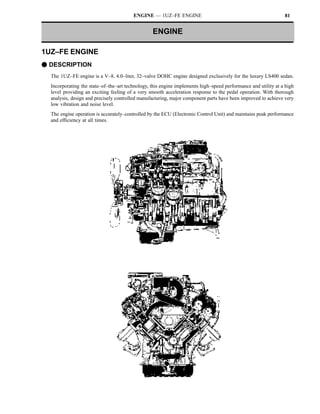
  • 1. ENGINE — 1UZ–FE ENGINE 81 ENGINE 1UZ–FE ENGINE F DESCRIPTION The 1UZ–FE engine is a V–8, 4.0–liter, 32–valve DOHC engine designed exclusively for the luxury LS400 sedan. Incorporating the state–of–the–art technology, this engine implements high–speed performance and utility at a high level providing an exciting feeling of a very smooth acceleration response to the pedal operation. With thorough analysis, design and precisely controlled manufacturing, major component parts have been improved to achieve very low vibration and noise level. The engine operation is accurately–controlled by the ECU (Electronic Control Unit) and maintains peak performance and efficiency at all times.
  • 2. 82 ENGINE — 1UZ–FE ENGINE F ENGINE SPECIFICATIONS AND PERFORMANCE CURVE Engine 1UZ–FE 1UZ FE Item No. of Cyls. & Arrangement 8–Cylinder, V Type Valve Mechanism 32–Valve, DOHC, Belt & Gear Drive Combustion Chamber Pentroof Type Manifolds Cross–flow Displacement cu. in. (cc) 242.1 (3,969) Bore x Stroke in. (mm) 3.44 x 3.25 (87.5 x 82.5) Compression Ratio 10.0 : 1 Firing Order 1–8–4–3–6–5–7–2 Max. Output (SAE–NET) 250 HP @ 5,600 rpm Max. Torque (SAE–NET) 260 ft.lbs @ 4,400 rpm Fuel Octane Number (RON) 96 Oil Grade* API SG, EC–II * Refer to the next page for detail.
  • 3. ENGINE — 1UZ–FE ENGINE 83 *NOTE: Engine oil selection Use API (American Petroleum Institute) grade SG, Energy–Conserving II multigrade engine oil. Recommended viscosity is as follows, with SAE 5W–30 being the preferred engine oil for the 1UZ–FE engine. DRecommended Viscosity (SAE)A A label is added to the oil filler cap and some oil containers to help you select the oil you should use. The top portion of the label shows the oil quality by API designations such as SG. The center portion of the label shows the SAE viscosity grade, such as SAE 5W–30. “Energy–Conserving II” shown in the lower portion, indicates that the oil has fuel–saving capabilities. DOil Identification LabelA Oils marked “Energy–Conserving II” will have higher fuel–saving capabilities than oils marked “Energy–Conserving.”
  • 4. 84 ENGINE — 1UZ–FE ENGINE F FEATURES OF 1UZ–FE ENGINE Features of the 1UZ–FE engine are shown in the following list: Features Contents S Compact DOHC, 32–valve, center–firing and high compression ratio combustion chamber implements a high combustion efficiency. High Performance S ECU–controlled precise engine operation. S Reduced intake and exhaust losses resulting from large–diameter intake duct, air flow meter, dual exhaust system, etc. S Reduced cylinder head size by the adoption of a scissors gear mechanism. Lightweight and Compact Design S Cylinder block and oil pan made of aluminum alloy. S Compact, lightweight accessory drive system by means of serpentine, single belt and bracketless accessory installation. S Use of an aluminum oil pan having an integral stiffener. S Aluminum engine mount brackets and liquid–filled compound engine mounts. Low Noise and Vibration S Silent start type three–stage temperature–controlled auto–coupling fan. S Rigid and accurately balanced crankshaft assembly. S Auto tensioners for timing belt and V–ribbed belt. S Outer shim type valve lifter. Serviceability S Auto tensioners for timing belt and V–ribbed belt. S Engine oil level sensor. S Thin cast–iron liner press–fit in aluminum cylinder block. High Reliability S Highly durable timing belt and auto tensioner. S Plastic region tightening bolts in major parts (cylinder head bolts, crankshaft bearing cap bolts, connecting rod cap bolts).
  • 5. ENGINE — 1UZ–FE ENGINE 85 F ENGINE 1. Cylinder Head S The cylinder head is made of aluminum and has intake and exhaust ports in a cross–flow arrangement. The intake ports are on the inside and the exhaust ports on the outside of the left and right banks respectively. S The cylinder heads are compact even for a DOHC engine. The pitch of the intake and exhaust camshafts is shortened and the valve angle is narrowed to 21_33′. S The left and right banks of cylinder heads are common in configuration. NOTICE When the cylinder heads are disassembled for servicing, be sure to assemble each cylinder head to the correct right or left bank. The camshaft may seize if they are assembled incorrectly. S Pentroof type combustion chamber with four valves is used. S The squish area guides the air–fuel mixture to the center of the combustion chamber to increase the combustion speed and thus maintain a stable engine operation. S Plastic region tightening bolts, having a good axial tension stability, are used for securing the cylinder heads to the block. NOTE: When reusing the cylinder head bolts, make sure the diameter at the thread is not less than 0.378 in. (9.6 mm). It will be necessary to replace them with new ones if the diameter is less than specification.
  • 6. 86 ENGINE — 1UZ–FE ENGINE 2. Cylinder Block S The cylinder block has a bank angle of 90_, a bank offset of 0.827 in. (21 mm) and a bore pitch of 4.15 in. (105.5 mm), resulting in a compact block in its length and width even for its displacement. S Lightweight aluminum alloy is used for the cylinder block. S A thin cast–iron liner is press–fit inside the cylinder to ensure an added reliability. NOTICE Never attempt to machine the cylinder because it has a thin 0.08 in. (2 mm) liner inside. S Part of the volute chamber of the water pump and the water by–pass passage are incorporated into the cylinder block to shorten the engine length. S Installation bosses of the two knock sensors are located on the inner side of left and right banks. S The plastic region tightening bolts are used for the crankshaft bearing caps. NOTE: When reusing the crankshaft bearing cap bolts, make sure the diameter at the thread is not less than 0.291 in. (7.4 mm). It will be necessary to replace them with new ones if the diameter is less than specification. S The starter is located inside the V–bank. S To install a local engine block heater, first remove the cover plate shown in the “A” view drawing below.
  • 7. ENGINE — 1UZ–FE ENGINE 87 NOTICE When fitting the crankshaft bearing cap, always tighten first and next in order to obtain roundness of the bearing.
  • 8. 88 ENGINE — 1UZ–FE ENGINE 3. Piston S Steel struts are used to control thermal expansion. S The skirt of each piston is striation finished (finely grooved) for maintaining proper lubrication and reducing friction loss. S The piston has a weight–adjusting boss to minimize fluctuation of weight among pistons and balance the engine assembly. S Piston pins are the full–floating type and are held in place with snap rings. 4. Piston Ring S Each surface of the compression ring No. 1 and the oil ring side rail is nitrified to prevent an increase of oil consumption and blow–by gas as the time elapses.
  • 9. ENGINE — 1UZ–FE ENGINE 89 5. Connecting Rod S The sintered and forged connecting rod is very rigid and has little weight fluctuation. S A weight–adjusting boss is provided at the big end to reduce fluctuation of weight and balance the engine assembly. S The connecting rod cap is held by plastic region tightening bolts. NOTE: When reusing the connecting rod cap bolts, if the diameter at the thread is less than 0.275 in. (7.0 mm), it is necessary to replace them with new ones. S The connecting rods for the right and left banks are placed in opposite directions with the outer marks facing the crankshaft.
  • 10. 90 ENGINE — 1UZ–FE ENGINE 6. Crankshaft and Crankshaft Bearings S A forged crankshaft with five main journals, four connecting rod pins and eight balance weights is used. S Connecting rod pins and journals are induction–hardened to ensure an added reliability. S Bearings are made of kelmet. S Crankshaft bearings are selected carefully according to the measured diameters of the crank journal and cylinder block journal holes. NOTE: The diameter of the crank journal and the cylinder block journal hole is indicated at the places shown below.
  • 11. ENGINE — 1UZ–FE ENGINE 91 NOTE: Numbers of the crankshaft and pistons are shown on the right side. Crankshaft angles and engine strokes (intake, compression, combustion and exhaust) are shown in the table below. The firing order is 1–8–4–3–6–5–7–2.
  • 12. 92 ENGINE — 1UZ–FE ENGINE F VALVE MECHANISM 1. General S Each cylinder has two intake valves and two exhaust valves. S The valves are directly opened and closed by four camshafts. S The intake camshafts are driven by a timing belt, while the exhaust camshafts are driven through gears on the intake camshafts. S Use of outer shim type valve lifters makes it easy to adjust the valve clearance without removing the camshaft.
  • 13. ENGINE — 1UZ–FE ENGINE 93 2. Camshafts S The exhaust camshafts are driven by gears on the intake camshafts. The scissors gear mechanism has been used on the exhaust camshaft to control backlash and reduce gear noise. S The camshaft journals and camshaft driven gear are lubricated by oil supplied to an oil passage in the center of the camshaft. Supply of oil from the cylinder heads to the camshafts is continuous, to prevent fluctuations in the oil pressure. S The cast iron camshafts are used. The cam nose is chill treated. S “T” type oil seals are used. NOTICE Be sure to follow the disassembly and reassembling procedures as directed in the Repair Manual to avoid possibility of damaging the cylinder head or camshaft timing gears (drive, driven and subgears).
  • 14. 94 ENGINE — 1UZ–FE ENGINE —REFERENCE— Scissors Gear Mechanism To prevent the tooth surfaces of gears from seizing or being damaged when the gears are engaged, they are designed to have backlash. However, backlash generates noise when changes in torque occur. The scissors gear mechanism is one means of preventing this noise. The scissors gear mechanism uses a subgear with the same number of teeth as the drive gear and is attached to the gear on the driven side. Through the reaction force of the scissors spring, these two gears act to pinch the drive gear, reducing backlash to zero and eliminating gear noise.
  • 15. ENGINE — 1UZ–FE ENGINE 95 3. Valve Lifter and Valve Adjusting Shims S Aluminum alloy valve lifters are used. S The valve adjusting shims used are of the outer shim type and are located on top of the valve lifters. It is not necessary to remove the camshafts in order to replace the shims when the valve clearance is adjusted. NOTE: (Method for replacing valve shims) Push down the valve lifter using an SST (Special Service Tool) to make a gap between the camshaft and the valve lifter. Direct compressed air from an air gun to the service hole in the valve adjusting shim to float the shim and remove it using a magnetic finger. Be sure to direct the air gun carefully so that you do not blow the shim away. 4. Timing Pulleys and Belt S An auto–tensioner is made up of a spring and oil damper, and maintains proper timing belt tension at all times. The auto–tensioner suppresses noise generated by the timing belt. S The timing belt has high heat resistance and durability. S The tooth profile of the timing belt is shown at the right. This design ensures a quiet operation and high–load transmission.
  • 16. 96 ENGINE — 1UZ–FE ENGINE F LUBRICATION SYSTEM 1. General S The lubrication is fully pressurized and all oil passes through an oil filter. S The oil pump is a trochoid gear type and is directly driven by the crankshaft.
  • 17. ENGINE — 1UZ–FE ENGINE 97 2. Oil Pan S The oil pan is made up of two pieces. No. 1 oil pan is made of aluminum alloy and No. 2 oil pan is made of steel. S The upper oil pan section is secured to the cylinder block and the torque converter housing, increasing rigidity. S The baffle plate controls the oil flow between the two oil pans when the vehicle is turning or is running along rough roads, etc. S An oil lever sensor is provided in the oil pan for efficient servicing. When the oil level falls below the specified level, the oil level sensor causes the low engine oil level warning light inside the combination meter to light up.
  • 18. 98 ENGINE — 1UZ–FE ENGINE F COOLING SYSTEM 1. Cooling Circuit S The cooling system is a pressurized, forced–circulation type. S A thermostat, having a bypass valve, is located on the water pump inlet side of the cooling circuit. As the coolant temperature rises, the thermostat opens and the bypass valve closes, so the system maintains suitable temperature distribution in the cylinder head. S A gauge coolant temperature sender, coolant temperature sensor, start injector time switch for the EFI (Electronic Fuel Injection) and BVSV (Bimetal Vacuum Switching Valve) for charcoal canister control are fitted to the front water joint. S The rear water joint has bypass outlet ports for heating the throttle body, cooling the EGR valve and hot water for the heater.
  • 19. ENGINE — 1UZ–FE ENGINE 99 2. Water Pump S The water pump has two volute chambers, and circulates coolant uniformly to the left and right banks of the cylinder block. S The water pump is driven by the back of the timing belt. S The rotor is made of resin. 3. Reservoir Tank S A pressurized valve is fitted to the reservoir. S A coolant level sensor is provided for efficient servicing. When the coolant level falls below the specified level, the coolant level sensor causes the low engine coolant level warning light inside the combination meter to light up. CAUTIONS 1. Never remove the cap while it is hot because the reservoir is also pressurized. 2. Engine coolant is replenished from the reservoir. To do so, first loosen the plug at the top of the inlet housing (shown on Page 98) to bleed air out of the cooling system. Be sure that the system is filled with coolant completely.
  • 20. 100 ENGINE — 1UZ–FE ENGINE 4. Coupling Fan S A three stage temperature–controlled auto coupling fan is used. The speed of the coupling fan changes in three stages based on the temperature of the air passing through the radiator. This keeps the fan speed low when the temperature is low, improving warm–up performance and reducing fan noise. The fan speed is high when the engine temperature is high, improving the cooling performance. Since part of the oil in the coupling fan is stored in the back storage chamber, the amount of oil in the operating chamber decreases at engine start. Oil resistance and the fan speed are reduced as a result immediately after engine start. The oil stored in the back storage chamber gradually flows into the operating chamber as the coupling fan keeps revolving. It eventually flows entirely into the operating chamber.
  • 21. ENGINE — 1UZ–FE ENGINE 101 F INTAKE AND EXHAUST SYSTEM 1. Air Cleaner The air cleaner case and cap are made of resin and have a large filtering capacity for the large engine displacement. The air cleaner element is a low air resistance type and allows the air to pass through it very smoothly. 2. Intake Air Resonator S A resonator is used to reduce the intake air noise. S The resonator is made of resin. The air passage and resonator chamber are formed separately. The resonator chamber is of the dual mode type and is separated by a partition.
  • 22. 102 ENGINE — 1UZ–FE ENGINE 3. Intake Air Chamber S The EGR and ISC (Idle Speed Control) passages are attached to the intake air chamber. S The start injector is located at the center of the intake air chamber so that fuel is distributed evenly to all cylinders. 4. Intake Manifold S Ports are crossed to increase the port length and inertia effects of the intake air.
  • 23. ENGINE — 1UZ–FE ENGINE 103 5. Exhaust Manifold S Both exhaust manifolds are made of stainless steel. S The exhaust manifolds are covered with heat insulators to protect the surrounding parts from exhaust heat. 6. Exhaust Pipe S The stainless steel exhaust pipe consists of three sections; the front, center and tail. The center section is single pipe while the front and tail are dual pipes to reduce exhaust resistance. S The catalyst converters (start and main) are of the monolithic type three–way catalysts. S The main catalyst converter is newly developed and has a high performance. S Large mufflers (main and sub) effectively reduce noise and exhaust pressure from the large capacity engine. * Applicable only to the California specification vehicles. Refer to page 161 for detail.
  • 24. 104 ENGINE — 1UZ–FE ENGINE F SERPENTINE BELT DRIVE SYSTEM S The serpentine belt drive system drives accessory components with a single V–ribbed belt. It reduces the overall engine length, weight and number of engine parts. S An automatic tensioner eliminates the need for tension adjustment. S The arm is pushed by the tension spring in a clockwise rotation direction always centering around “Z”. The pulley’s center of rotation is bolted to the arm. For this reason, when the belt stretches with time, the pulley center of rotation rotates to the right in an arc around “Z” with the arm. Thus the belt tension is always maintained appropriately. NOTICE S Check the indicator mark. If it is outside the operation range, replace the belt. S When a new belt is installed, the graduations must be in the area indicated by “A” in the picture.
  • 25. ENGINE — 1UZ–FE ENGINE 105 F ENGINE MOUNTING 1. General S Liquid–filled compound engine mounts are fitted on both sides of the engine to reduce vibration and noise at all speeds. S The aluminum engine mounting brackets reduce vibration and noise and minimize the total engine weight. 2. Liquid–Filled Compound Engine Mount The engine mount combines rubber with liquid filled chambers. The fluid flows between upper and lower chambers through an orifice. In addition to vibrations being absorbed by the rubber mounting, low frequency vibration is absorbed by the fluid flowing through the orifice. Also, by decreasing the elasticity of the rubber, the dynamic spring constant has been reduced, providing greater noise reduction in the case of high frequency vibrations.
  • 26. 106 ENGINE — 1UZ–FE ENGINE F STARTING SYSTEM 1. Starter S The starter output is 2.0 KW and is located inside the V–bank of the cylinder block. F CHARGING SYSTEM 1. Alternator S The IC regulated alternator has a large output of 1200 watts to produce enough electricity for the electric load. S The alternator is fitted directly (without brackets) to the cylinder block.
  • 27. ENGINE — 1UZ–FE ENGINE 107 F ENGINE MOUNTING 1. General Engine control system uses an ECU (Electronic Control Unit) with a built–in microprocessor. Stored inside the ECU is the data for fuel injection duration, ignition timing and idling speed, etc. which are matched with the various engine conditions as well as programs for calculation. The ECU utilizes these data and signals from the various sensors in the vehicle and makes calculations with the stored programs to determine fuel injection duration, ignition timing and idling speed, etc., and outputs control signals to the respective actuators which control operation. The engine ECU and transmission ECU are integrated into one and the ECU is called the engine and transmission ECU. The engine control system for the 1UZ–FE engine has the following functions: EFI (Electronic Fuel Injection) The ECU determines the fuel injection duration according to intake air volume, engine speed, coolant temperature and other signals and sends control signals to the fuel injectors. Also, this fuel injection duration is the basis for deciding the fuel injection timing. The fuel injection system in the 1UZ–FE engine is a four group injection system which injects fuel simultaneously into two cylinders once every two engine revolutions. ESA (Electronic Spark Advance) The ECU determines the amount of ignition advance over the initial set timing of the distributor by the intake air volume, engine speed, coolant temperature and other signal and sends control signals to the igniters. Also, based on signals from the knock sensors, the ECU controls the ignition timing at the optimum in accordance with the gasoline’s octane value. ISC (Idle Speed Control) By means of engine speed signals and coolant temperature signals, the ECU sends control signals to the ISC valve so that the actual idling speed becomes the same as the target idling speed stored in the ECU. Also, while the engine is warming up, the ECU, based on coolant temperature signals, sends controls signals to the ISC value to control engine speed to fast idle. EGR (Exhaust Gas Recirculation) CUT CONTROL The ECU sends signals to the EGR VSV to cut the EGR based on coolant temperature, engine speed, neutral start switch or intake air volume signals. This system maintains drivability at low coolant temperature, under light or heavy load conditions, or at high engine speed, etc. FUEL PRESSURE CONTROL The ECU sends signals to the pressure regulator VSV based on coolant temperature, intake air temperature, vehicle speed and engine start signals, and increases the fuel pressure. This system maintains restartability and idling stability when the engine is hot. FUEL PUMP SPEED CONTROL The ECU, based on fuel injection duration, sends control signals to the fuel pump control relay to control the fuel pump speed. That is, when the engine requires a large volume of fuel, the fuel pump turns at high speeds and when only a small volume of fuel is required, the pump turns at low speeds.
  • 28. 108 ENGINE — 1UZ–FE ENGINE OXYGEN SENSOR HEATER CONTROL Based on the intake air volume, engine start and coolant temperature signals, the ECU sends control signals to the oxygen sensor heater. This system maintains the oxygen sensor at the appropriate temperature in order to improve the detecting accuracy of oxygen concentration in the exhaust gas. AIR CONDITIONER CONTROL Based on the air conditioner switch signal from the air conditioner ECU, the ECU sends control signals to the magnetic clutch of the air conditioner compressor. This system, the magnetic clutch operation, is delayed for a predetermined period after the air conditioner switch is turned on. DIAGNOSIS The ECU is constantly monitoring signals from each sensor. If a malfunction occurs with the signals, the CHECK ENGINE lamp on the combination meter lights up and informs the driver of the malfunction. The content of the malfunction is stored in code in the ECU and when the TE1 and E1 terminals in the check connector or TDCL are connected, the ECU outputs the trouble code by flashing the CHECK ENGINE lamp. FAIL–SAFE If the ECU judges from the signals from each sensor that there is a malfunction, it continues the engine operation using its own data or it stops the engine.
  • 29. ENGINE — 1UZ–FE ENGINE 109 2. Construction The engine control system can be broadly divided into three groups: the ECU, the sensor and the actuators. 1 Applicable only to California specification vehicles. *2 Applicable only to vehicles equipped with the optional TRAC (Traction Control) system
  • 30. 110 ENGINE — 1UZ–FE ENGINE 3. Summary of Engine Control System The following list summarizes each system and control composing engine control system of the 1UZ–FE engine and types of the related sensors, ECU and others. *1: Applicable only to California specification vehicles. *2: Applicable only to vehicles equipped with the optional TRAC (Traction Control) system
  • 31. ENGINE — 1UZ–FE ENGINE 111 4. Engine Control System Diagram *1: Applicable only to California specification vehicles. *2: Applicable only to vehicles equipped with the optional TRAC (Traction Control) system
  • 32. 112 ENGINE — 1UZ–FE ENGINE 5. Arrangement of Engine Control System Components
  • 33. ENGINE — 1UZ–FE ENGINE 113 6. EFI (Electronic Fuel Injection) The EFI system consists of the following three major systems: 1) Fuel System 2) Air Induction System 3) Electronic Control System Fuel System 1) General Fuel is pumped under pressure by the electric fuel pump from the fuel tank, through the fuel filter, to the injectors and the cold start injector. The pressure regulator controls the amount of fuel being returned to the fuel tank through the return pipe, thus adjusting the pressure of fuel to the injectors. The pulsation damper absorbs the minute fluctuations in fuel pressure due to injection of fuel. The injectors inject fuel into the intake port in accordance with injection duration signals from the ECU. The cold start injector injects fuel into the air intake chamber when the coolant temperature is low, improving startability in cold weather.
  • 34. 114 ENGINE — 1UZ–FE ENGINE 2) Fuel Pump An in–tank type fuel pump is provided inside the fuel tank. A turbine pump, with little discharge pulsation of the fuel in the pump, is used. This pump consists of the motor portion and the pump portion, with a check valve, relief valve and filter also incorporated into the unit. a. Turbine Pump The turbine pump consists of the impeller, which is driven by the motor, and the casing and pump cover, which compose the pump unit. When the motor turns, the impeller turn along with it. Blades on the outer circumference of the impeller pull fuel from the inlet port to the outlet port. Fuel discharged from the outlet port passes through the motor portion and is discharged from the pump through the check valve. b. Relief Valve The relief valve open when the discharge side pressure reaches 71.1!92.3 lb/in.2 (5.0!6.5 kg/cm 2) and the high pressure fuel is returned directly to the fuel tank. The relief valve prevents the fuel pressure from rising beyond that level. c. Residual Pressure Check Valve The check valve closes when the fuel pumps stops. The residual pressure check valve and pressure regulator both work to maintain residual pressure in the fuel line when the engine is stopped, thus easing restartability. If there were no residual pressure, vapor lock could occur easily at high temperatures, making it difficult to restart the engine. S The 1UZ–FE engine has a fuel pump speed control (ECU controlled) system which regulates the amount of electricity flowing to the fuel pump and thus the amount of fuel delivery according to the engine load. See page 149 for detail.
  • 35. ENGINE — 1UZ–FE ENGINE 115 3) Fuel Filter The fuel filter filters out dirt and other foreign particles from the fuel. It is installed at the high pressure side of the fuel pump. 4) Pulsation Damper Fuel pressure is maintained at 41 lb/in.2 (2.9 kg/cm 2) in relation to the manifold vacuum, by the pressure regulator. However, there is a slight variation in line pressure due to injection. The pulsation damper acts to absorb this variation by means of a diaphragm.
  • 36. 116 ENGINE — 1UZ–FE ENGINE 5) Pressure Regulator a. Function The pressure regulator regulates the fuel pressure to the injectors. Fuel injection quantity is controlled by the duration of the signal applied to the injectors, so that a constant pressure must be maintained to the injectors. However, as fuel is injected into the intake port and manifold vacuum varies, the fuel injection quantity will vary slights even if the injection signal and fuel pressure are constant. Therefore, to acquire an accurate injection quantity, the sum of the fuel pressure A and intake manifold vacuum B must be maintained at 41 lb/in.2 (2.9 kg/cm2). b. Operation Pressurized fuel from the delivery pipe pushes on the diaphragm, opening the valve. Part of the fuel flows back to the fuel tank through the return pipe. The amount of fuel return depends on the extent of the diaphragm spring tension and the fuel pressure varies according to the return fuel volume. Intake manifold vacuum is led to the chamber of the diaphragm spring side, weakening the diaphragm spring tension, increasing the volume of return fuel and lowering the fuel pressure. In short, when intake manifold vacuum rises (less pressure), fuel pressure falls only to the extent of the decrease in pressure, so that sum of the fuel pressure A and the intake manifold vacuum B is maintained at a constant. The valve is closed by the spring when the fuel pump stops. As a result, the check valve inside the fuel pump and the valve inside the pressure regulator maintain residual pressure inside the fuel line. S The 1UZ–FE engine has a fuel pressure control (ECU controlled) system which maintains the fuel pressure at higher levels than normal for a predetermined time when the engine is hot when started, maintaining the engine startability and the idle stability. See page 150 for detail.
  • 37. ENGINE — 1UZ–FE ENGINE 117 6) Fuel Injector Fuel is injected into the intake port of each cylinder in accordance with injection signals from the ECU. At the tip of the injector, there are two injection holes. The light and small plunger permits quick response to signals from the ECU. When a signal from the ECU is received by the solenoid coil, the plunger is pulled against spring force. Since the valve needle and plunger are a single unit, the valve needle is also pulled from its seat and fuel is injected. Fuel volume is controlled by the duration of the signal. 7) Cold Start Injector The cold start injector injects fuel into the intake air chamber during engine cranking to improve startability. In starting the engine when the engine coolant temperature is 71.6_F (22_C) or lower, the cold start injector’s operation time is controlled by the start injector time switch. However, starting the engine when engine coolant temperature is 140_F (60_C) or lower, the operation time of the cold start injector is controlled by the ECU. Thus, the cold start injector is controlled by the start injector time switch and the ECU simultaneously when the coolant temperature is below 71.6_F (22_C).
  • 38. 118 ENGINE — 1UZ–FE ENGINE Air Induction System 1) General Air cleaned by the air cleaner enters the air intake chamber according to the throttle valve opening in the throttle body and the engine speed. An optical Karman–Vortex type air flow meter is provided between the air cleaner and the throttle body to optically detect the frequency of the Karman–Vortex that is generated when the air passes to measure the amount of air being taken into the engine. A throttle valve in the throttle body controls the air volume. The air regulated by the throttle valve enters the air intake chamber, is distributed to the intake manifold of each cylinder and enters the combustion chamber. ISC (Idle Speed Control) valve is also provided on the throttle body and directs the intake air bypassing the throttle body to the air intake chamber. The amount of air bypassing the throttle body is determined by a signal from the ECU to control the idle speed and fast idle speed accordingly. The air intake chamber prevents pulsation of the intake air to minimize the adverse affection to the air flow meter. This helps to increase accuracy of measurement of the intake air volume. It also prevents intake air interference in cylinders.
  • 39. ENGINE — 1UZ–FE ENGINE 119 2) Construction and Operation of Main Components a. Air Flow Meter S Description An optical Karman–Vortex type air flow meter is used. This air flow meter measures the intake air volume electrically, enabling precise detection. It is made compact and lightweight. The simplified construction of the air passage also reduces air intake resistance. S Principle Karman–Vortex Street When a cylindrical object (Vortex generating body) is placed in the path of gaseous current, vortices (called Karman–Vortex) are generated in the wake of the object. If the Karman–Vortex frequency is f, the air velocity V and the diameter of the cylindrical object d, then the following equation can be made: S Construction and Operation Using the above principle, the air flow meter is fitted with a vortex generator. As air flows past the vortex generator, vortices are generated at a frequency proportional to the velocity of the air flow. A calculation of the frequency can then determine the amount of air flow. The vortices are detected by subjecting the surface of thin metal foil (mirror) to the pressure of the vortices and optically detecting the vibrations in the mirror by means of a luminous diode and a photo transistor. The intake air volume signal (Ks) is the pulse signal. When the intake air volume is low, this signal has a low frequency. When the intake air volume is high, it has a high frequency.
  • 40. 120 ENGINE — 1UZ–FE ENGINE b. Throttle Body The throttle body contains the throttle valve that regulates the amount of intake air, the throttle position sensor that detects the throttle valve opening, and the dash pot that reduces the closing speed of the throttle valve. The throttle body has the following features: S The throttle body contains a throttle valve, sufficiently large in diameter to meet the large engine displacement. S A linear type throttle position sensor is mounted on the throttle valve shaft. This sensor detects the throttle valve opening angle, converts it to a voltage and sends it to the engine and transmission ECU. (Refer to the next page for detail.) S Engine coolant passes through the throttle body to maintain warmth under cold weather conditions. S When the optional TRAC (Traction Control) is fitted, a sub–throttle actuator, sub–throttle valve and sub–throttle position sensor are added to the throttle body.
  • 41. ENGINE — 1UZ–FE ENGINE 121 S Throttle Position Sensor The throttle position sensor is mounted on the throttle body. This sensor converts the throttle opening angle into a voltage and sends it to the ECU as the throttle position signal. A constant 5V is applied to the Vcc terminal from the ECU. As the contact slides along the resistor in accordance with the throttle valve opening angle, a voltage is applied to the VTA terminal in proportion to this angle. When the throttle valve is closed completely, the contact for the IDL signal connects between the IDL and E2 terminals. Another throttle position sensor for the sub–throttle valve is added to the vehicle with the optional TRAC (Traction Control). It is the same as the main throttle position sensor in construction and operation.
  • 42. 122 ENGINE — 1UZ–FE ENGINE Electronic Control System 1) General The ECU incorporates a built–in microprocessor. It controls injection duration precisely based on the data stored in its memory and signals from each sensor. Also, the ECU, based on this injection duration, controls the ignition timing. Further, the fuel injection system is a four group injection system. The ECU controls to inject fuel into two cylinders simultaneously once every two engine revolutions. DFuel Injection TimingA
  • 43. ENGINE — 1UZ–FE ENGINE 123 2) Construction and Function of Relevant Sensors a. Cam Position Sensors and Engine Speed Sensor S General Revolution of the G signal plate on the camshaft and Ne signal plate on the crankshaft alters the air gap between the projection of the plate and the G pickup coil (or the Ne pickup coil). The change in the gap creates an electromotive force in the pickup coil. This voltage appears as an alternating output since it reverses its direction periodically as the plate approaches and leaves the pickup coil. S Cam Position Sensors (G1 and G2 signals) The G1 signal informs the ECU of the standard crankshaft angle, which is used to determine injection timing and ignition timing in relation to TDC of No. 6 cylinder. G2 sensor conveys the same information for No. 1 cylinder. These sensors are made up of (1) signal plate, which is fixed to the camshaft timing pulley and turn once for every two rotations of the crankshaft, and (2) the two sensors (G1 and G2 sensors), which are fitted to the distributor housing. The G1, G2 signal plates are provided with a projection which activates the G1 and G2 sensors once for each rotation of the camshaft, generating the wave forms as shown in the chart. From these signals, the ECU detects when the No. 6 and No. 1 pistons are near their TDC.
  • 44. 124 ENGINE — 1UZ–FE ENGINE S Engine Speed Sensor (Ne signal) The Ne signal is used by the ECU to detect the actual crankshaft angle and the engine speed. The ECU determines the basic injection duration and basic ignition advance angle by these signals. Ne signals are generated in the Ne sensor by the Ne signal plate like the G1 and G2 signals. The only difference is that the signal plate for the Ne signal has 12 teeth. Therefore, 12 Ne signals are generated per engine rotation. From these signals, the ECU detects the engine speed as well as each 30_ change in the engine crankshaft angle.
  • 45. ENGINE — 1UZ–FE ENGINE 125 b. Oxygen Sensors Four oxygen sensors in total are fitted, one each in front of and after the start catalyst converters. The one in front of the catalyst converter is the main oxygen sensor and after the converter is the sub–oxygen sensor. The main and sub–oxygen sensors are identical in construction and function, except for the fact that the main oxygen sensor has a heater. The O2 sensor consists of a test tube shaped zirconia element with a thin layer of platinum coated to both the inside and outside. This sensor is fitted to the exhaust manifolds and exhaust pipes on both the left and right sides to sense oxygen concentration (air–fuel ratio) in the exhaust gas. If there is a difference in the oxygen concentration on the two sides of the zirconia element, an electromotive force is generated, or if the temperature of the O2 sensor becomes high, the platinum acts as a catalyst, causing the oxygen in the exhaust gas to react with the CO. This decreases the oxygen volume in the gas. The zirconia element’s electromotive force changes suddenly at the boundary near the ideal air–fuel ratio. Using these properties, exhaust gas is passed over the outer surface of the O2 sensor and atmospheric air is introduced into the inside of the sensor. The sensor accurately detects whether the oxygen concentration, that is, the air–fuel ratio, is higher (rich) or lower (lean) than the ideal air–fuel ratio. If the air–fuel is rich, the zirconia element generates high voltage (approximately 1V). This “rich” signal is sent to the ECU. Conversely, if the air–fuel ratio is lean, the electromotive force of the O2 sensor is low. The ECU increases or decreases the injection volume in accordance with these signals. A heater is provided in the sensors which are fitted to the exhaust manifolds. It heats the zirconia element. This heater is controlled by the ECU. When the intake air volume is low (the exhaust gas temperature is low), current flows to the heater, maintaining the sensor accuracy.
  • 46. 126 ENGINE — 1UZ–FE ENGINE 3) Functions of the ECU a. Determination of Injection Timing When the ECU receives the G1 signal from the cam position sensor and then the Ne signal from the engine speed sensor in this order, it determines that the crankshaft angle at No. 6 cylinder is at 5_ BTDC position. When the Ne signal is received immediately after the G2 signal, it judges that the crankshaft angle at No. 1 cylinder is at 5_ BTDC. The ECU accurately calculates the crankshaft angle based on G1, G2 and Ne signals and determines the injection timing accordingly. b. Principle of Fuel Injection Duration Control The fuel injection duration is determined by the basic injection duration which is determined by intake air volume and the engine speed, plus any compensation based on signals from various sensors. During engine starting (cranking), it is determined differently because the amount of intake air is not stable during cranking. Once the engine is started, the ECU determines the duration of injection in the following steps: Step 1: Determination of Basic Injection Duration The ECU selects, from the data stored in its memory, an injection duration that is suitable for the intake air volume (detected by the air flow meter) and the engine rpm (detected by the engine speed sensor). This injection duration is called the “basic injection duration.” Step 2: Determination of Adjusted Duration of Injection Under most engine condition, the engine runs smoothly at an air–fuel mixture ratio of approximately 14.7 (this is called the “ideal air–fuel ratio”). However, when the engine is still cold, or when an extra load is applied to the engine, the air–fuel ratio is reduced to below 14.7 (i.e., it becomes richer). The ECU detects these engine conditions by means of the water temp. sensor, throttle position sensor and intake air temp. sensor, etc., and corrects the basic injection duration to optimize it for the existing engine conditions. Also, even under normal engine conditions, the injection duration is corrected by the signals from the oxygen sensors to keep the air–fuel ratio within a narrow range near 14.7. The corrected time is called the “adjusted injection duration”. Step 3: Determination of Injection Signal Length There is a slight delay between the time the ECU sends an injection signal to the injectors and the time the injectors actually open. This delay becomes longer the more the voltage of the battery drops. The ECU compensates for this delay by lengthening the injection signal by a period corresponding to the length of the delay. This corrects the actual injection period so that it corresponds with that calculated by the ECU.
  • 47. ENGINE — 1UZ–FE ENGINE 127 c. Starting Injection Control During engine starting, it is difficult for the air flow meter to accurately sense the amount of air being taken in due to large fluctuations in rpm. For this reason, the ECU selects from its memory an injection duration that is suitable for the coolant temperature, regardless of intake air volume or engine rpm. It then adds to this an intake air temperature correction and a voltage correction, to obtain the injection duration. RELEVANT SIGNALS S Engine speed (Ne) S Coolant temperature (THW) S Intake air temperature (THA) S Ignition switch (STA) S Battery voltage (+B) S Throttle position sensor (VTA1, VTA2) CONDITIONS Engine speed below a predetermined level, or STA on.
  • 48. 128 ENGINE — 1UZ–FE ENGINE d. After–Start Injection Control When the engine is running more or less steadily above a predetermined level rpm, the ECU determines the injection signal duration as explained below: Injection Signal Duration = Basic Injection Duration x Injection Correction Coefficient* + Voltage Correction * Injection correction coefficient is calculated by the sum and product of various correction coefficients. i) Basic Injection Duration This is the most basic injection duration, and is determines by the volume of air being taken in (Ks signal) and the engine speed (Ne signal). The basic injection duration can be expressed as follows: * The intake air volume may vary with the air density due to fluctuation of the air temperature and atmospheric pressure. The variation of air density is corrected as follows: S Intake Air Temperature Correction The density of the intake air will RELEVANT SIGNAL change depending upon its Intake air temperature (THA) temperature. For this reason, the ECU must be kept accurately informed of both the intake air volume (by means of the air flow meter) and the intake air temperature (by means of the intake air temp. sensor) so that it can adjust the injection duration to maintain the air–fuel ratio currently required by the engine. For this purpose, the ECU considers 68_F (20_C) to be the “standard temperature” and increases or decreases the amount of fuel injected, depending upon whether intake air temperature falls below or rises above this standard.
  • 49. ENGINE — 1UZ–FE ENGINE 129 S High Altitude Compensation The density of oxygen in the RELEVANT SIGNAL atmosphere is smaller at high High altitude compensation (HAC) altitudes. If the fuel is injected under the same conditions as sea level, the amount of intake air volume measured by the air flow meter for mixture with the fuel will be insufficient and the air–fuel mixture becomes too rich. For this reason, the ECU, according to signals from the high altitude compensation sensor, adjusts signals from the air flow meter and determines the corresponding fuel injection volume. ii) Injection Corrections The ECU is kept informed of the engine running conditions at each moment by means of signals from various sensors, and makes various corrections in the basic injection duration based on these signals. S After–Start Enrichment Immediately after starting (engine RELEVANT SIGNAL speed above a predetermined rpm), the ECU causes an extra amount of S Engine speed (Ne) fuel to be supplied for a certain period S Coolant temperature (THW) to aid in stabilizing engine operation. The initial correction value is determined by the coolant CONDITION temperature, and the amount Engine speed above a predetermined rpm gradually decreases thereafter at a certain constant rate. S Warm–Up Enrichment As fuel vaporization is poor when the RELEVANT SIGNAL engine is cold, if a richer fuel mixture is not supplied, the engine will run S Engine speed (Ne) poorly. S Coolant temperature (THW) For this reason, when the coolant temperature is low, the water temp. sensor informs the ECU to increase the amount of fuel injected to compensate. As the coolant warms up, the amount of warm–up enrichment decreases, reaching zero (correction coefficient = 1.0) when the coolant reaches 140_F (60_C).
  • 50. 130 ENGINE — 1UZ–FE ENGINE S Acceleration Enrichment During Warm–Up The ECU causes an extra fuel to be RELEVANT SIGNALS supplied during acceleration when the S Air flow meter (Ks) engine is still warming up in order to aid drivability. S Engine speed (Ne) Through calculation of the amount of S Coolant temperature (THW) change in the intake air volume per engine revolution, the ECU detects S Intake air temperature (THA) the engine acceleration or S Ignition switch (STA) deceleration condition. The correction value is determined S High altitude compensation (HAC) according to the coolant temperature and the strength of acceleration or CONDITIONS deceleration. Intake air volume per engine revolution changes The control is performed separately (acceleration or deceleration) with coolant for each bank. temperature below 176_F (80_C). However, if any of the following occurs, the ECU stops calculating this change and halts the injection of extra fuel: S Engine speed falls below a predetermined rpm S Fuel cut–off occurs S Intake air volume becomes smaller than a certain level S Power Enrichment When the engine is operating under RELEVANT SIGNALS heavy load conditions, the injection volume is increased in accordance S Throttle position (VTA1,2) with the engine load in order to ensure S Air flow meter (Ks) good engine operation. S Engine speed (Ne) The correction value is determined according to the intake air volume or S Coolant temperature (THW) throttle valve opening angle. S Intake air temperature (THA) S High altitude compensation (HAC) CONDITIONS Throttle valve opening angle above 60_ or intake air volume larger than a certain level.
  • 51. ENGINE — 1UZ–FE ENGINE 131 S Air–Fuel Ratio Feedback Correction The ECU corrects the ignition duration based on the signals from the main oxygen sensors to keep the air–fuel ratio within a narrow range near the ideal air–fuel ratio. (Closed look operation) Further, in order to prevent overheating of the catalyst and assure drivability under the following conditions, the air–fuel ratio feedback operation does not work: (Open loop operation) S During engine starting S During traction control S During after–start S Fuel cut–off occurs enrichment S Coolant temperature below a predetermined level The ECU compares the voltage of the signals sent from the main oxygen sensors with a predetermined voltage. As a result, if the voltage of the signal is higher, the air–fuel ratio is judged to be richer than the ideal air–fuel ratio and the amount of fuel injected is reduced at a constant rate. If the voltage of the signal is lower, it is judged that the air–fuel ratio is leaner than the ideal, so the amount of fuel injected is increased. In addition, the ECU corrects the skip amount of “rich” or “lean” mixture based upon signals from the two sub–oxygen sensors. This implements a more accurate feedback correction. The control is performed separately for each bank. iii) Voltage Correction There is a slight delay between the time the ECU sends an injection signal to the injectors actually open. This delay becomes longer the more the voltage of the battery drops. This means that the length of time that the injector valves remain open would become shorter than that calculated by the ECU, causing the actual air–fuel ratio to become higher (i.e., leaner) than that required by the engine, if this were not prevented by voltage correction. In voltage correction, the ECU compensates RELEVANT SIGNALS for this delay by lengthening the injection signal by a period corresponding to the length Battery voltage (+B) of the delay. This corrects the actual injection period so that it corresponds with that calculated by the ECU.
  • 52. 132 ENGINE — 1UZ–FE ENGINE e. Fuel Cut–Off S Fuel Cut–Off During Deceleration RELEVANT SIGNALS During deceleration from a high engine speed S Throttle position (IDL1) with the throttle valve completely closed, the ECU halts injection of fuel in order to improve S Engine speed (Ne) fuel economy and emission. S Coolant temperature (THW) When the engine speed falls below a certain rpm or throttle valve is opened, fuel injection is resumed. These fuel cut–off and fuel CONDITION injection resumption speeds are high when the IDL contacts are closed with engine speed above fuel coolant temperature is low. cut–off speed. CONDITIONS FOR RESUMPTION OF FUEL INJECTION Engine speed drops below fuel injection resumption speed, or IDL contacts are open. S Fuel Cut–Off Due to High Engine Speed To prevent engine over–run, fuel injection is halted if the engine speed rises above 6500 rpm. Fuel injection is resumed when the engine speed falls below this level. f. Cold Start Injector Control To improve startability when the engine is cold, RELEVANT SIGNALS the injection duration of the cold start injector is controlled not only by the start injector time S Coolant temperature (THW) switch but by the ECU in accordance with the S Ignition switch (STA, IGSW) coolant temperature. Once the engine has been S Engine speed (Ne) started, current to the cold start injector is cut off and injection is terminated. CONDITION The engine is cranking and the coolant temperature is below 140_F (60_C).
  • 53. ENGINE — 1UZ–FE ENGINE 133 7. ESA (Electronic Spark Advance) General In order to maximize engine output efficiency, the air–fuel mixture must be ignited when the maximum combustion pressure occurs; that is, at about 10_ after TDC. However, the time from ignition of the air–fuel mixture to the maximum combustion pressure varies depending on the engine speed and the intake air volume. Ignition must occur earlier when the engine speed is higher. In the conventional system, the timing is advanced by the governor advancer. When the intake air volume per engine revolution is small (high vacuum), ignition must also be advanced, and this is achieved by the vacuum advancer in the conventional system. Actually, optimum ignition timing is affected by a number of other factors, such as the shape of the combustion chamber and the temperature inside the combustion chamber, etc., in addition to the engine speed and the intake air volume. Therefore, the governor and vacuum advance do not provide ideal ignition timing for the engine. With the ESA (Electronic Spark Advance) system, the engine is provided with nearly ideal ignition timing characteristics. The ECU determines ignition timing from its internal memory, which contains optimum ignition timing data for each engine condition, based on signals detected by various sensors, and then sends signals to the igniter. Since the ESA always ensures optimum ignition timing, both fuel efficiency and engine power output are maintained at optimum levels. DVacuum AdvancingA DGovernor AdvancingA DESAA DConventionalA
  • 54. 134 ENGINE — 1UZ–FE ENGINE Ignition Circuit 1) Principle of Ignition The ignition timing is determined by the ECU based on signals (G1, G2, Ne) from sensors. When it is determined, the ECU sends an IGt signal to the igniter at a predetermined timing (30_ crankshaft angle) before ignition. The transistor inside the igniter is turned on by this signal and primary current is supplied from the battery via the ignition switch to the ignition coil. When the crankshaft position reaches the ignition timing, the ECU stops supplying the IGt signal. The transistor inside the igniter is turned off and the primary current to the ignition coil is cut off as a result. At this time, the secondary voltage is induced in the ignition coil. The secondary voltage is distributed and causes sparks from the spark plug. The counter–electromotive force that is generated when the primary current is shut off causes an ignition confirmation signal (IGf), which is sent to the igniter. NOTE: Two igniters are used in the engine, one each for four cylinders. No. 1 igniter ignites cylinders 1, 4, 6 and 7 and No. 2 igniter ignites cylinders 2, 3, 5 and 8. 2) Layout of Components
  • 55. ENGINE — 1UZ–FE ENGINE 135 Construction and Function of Relevant Sensor Knock Sensor The knock sensor is provided on the left and right banks of the cylinder block. A piezoelectric ceramic element is incorporated into the sensor. If knocking develops in the engine, this piezoelectric element, by resonating with the knocking vibration, generates a voltage which corresponds with the knocking strength and sends a signal to the ECU. The ECU uses this signal to retard the ignition timing to prevent the knocking. —REFERENCE— Excessive knocking may damage the engine. However, the engine operation in a marginal knocking condition is the most advantageous to the engine output and fuel economy.
  • 56. 136 ENGINE — 1UZ–FE ENGINE Function of ECU 1) The function of the ECU in the ESA control is divided into the following three items: a. Judging Crankshaft Angle In order to control the ignition timing, it is necessary for the ECU to know where compression top dead center is. In this engine, the ECU judges that the crankshaft has reached 5_ BTDC of the compression cycle when it receives the first Ne signal following a G1 (or G2) signal. Therefore, the ECU calculates the ignition timing, and advances or retards the timing accordingly, using 5_ BTDC as a reference point. If the ignition timing is set to 10_ BTDC with terminals TE1 and E1 shorted, the crankshaft angle will be 10_ BTDC at the time of the next Ne signal after the G1 (or G2) signal. This is known as the initial ignition timing. b. Calculating Ignition Timing The ECU selects the basic ignition advance angle from the values stored in its memory based on the intake air volume and engine speed, then adds corrections based on signals from each sensor to determine the actual ignition timing. Ignition Timing = Initial Ignition Timing + Basic Ignition Advance Angle + Corrective Ignition Advance (or Retard) Angle c. Igniter Control The ECU sends an ignition timing signal (IGt1,2) to the igniter based on signals from each sensor so as to achieve the optimum ignition timing. This ignition timing signal goes on just before the ignition timing calculated in the ECU, then the ignition timing signal goes off. The spark plug fires at the point when this signal goes off.
  • 57. ENGINE — 1UZ–FE ENGINE 137 2) Ignition Timing Control Ignition timing control consists of two basic elements: 1) Ignition control during starting (while the engine is cranking, ignition occurs at a certain fixed crankshaft angle, regardless of engine operating conditions); and 2) After–start ignition control, in which various corrections (made by the ECU based on signals from the relevant sensors) are added to the basic advance angle, which is determined by the intake air volume signal and the engine speed signal during normal operation.
  • 58. 138 ENGINE — 1UZ–FE ENGINE a. Starting Ignition Control Since the engine speed is still below a RELEVANT SIGNALS specified rpm and unstable during and immediately after starting, the ECU cannot S Engine speed (Ne) accurately determine the correct ignition timing. For this reason, the ignition timing is S Ignition switch (STA) fixed at the initial ignition timing of 5_ BTDC until engine operation is stabilized. CONDITIONS Engine speed below specified rpm, or STA on. NOTE: At engine adjustment time, etc., with the vehicle stopped, confirm the ignition timing by connecting the TE1 and E1 terminals in the check connector or TDCL with the throttle valve fully closed. Under the above conditions, ignition advance should not be occurring and the ignition timing should be the initial ignition timing (10_ BTDC). b. After–Start Ignition Control i) Basic Ignition Advance Angle Control This corresponds to the vacuum advance and governor advance angles in conventional type ignition system. The memory in the ECU contains optimum advance angle data for the intake air volume and the engine speed. The ECU selects the basic ignition advance angle from memory according to the engine speed signals from the engine speed sensor and the intake air volume signals from the air flow meter. S IDL Contacts Open (OFF) When the IDL contacts open, the ECU determines the basic ignition advance angle based upon data stored in the memory. This data can be shown in the form of a table, as shown in the chart. RELEVANT SIGNALS DBasic Ignition Advance Angle DataA S Air flow meter (Ks) S Engine speed (Ne) S Throttle position (IDL1) S Intake air temperature (THA) S High altitude compensation (HAC) —REFERENCE— Since the capacity of the ECU’s memory is limited, it cannot hold all possible advance angle data. For this reason, the ECU selects the value that is the closest to the required value for each particular combination of engine speed and intake air volume. It then carries out proportional calculations to find the optimum ignition timing for the given engine speed and the intake air volume. S IDL Contacts Closed (ON) When the IDL contacts close, the ignition timing is advanced as shown, in accordance with the engine speed, whether the air conditioner is on or off, and whether neutral start switch is on or off. RELEVANT SIGNALS S Throttle position (IDL1) S A/C switch (A/C) S Engine speed (Ne) S Neutral start switch (NSW) S Vehicle speed (SP1)
  • 59. ENGINE — 1UZ–FE ENGINE 139 ii) Corrective Ignition Advance Angle Control S Warm–Up Correction When the coolant temperature is low, RELEVANT SIGNALS the ignition timing is advanced S Coolant temperature (THW) according to it to improve drivability. S Intake air volume (Ks) S Engine speed (Ne) S Intake air temperature (THA) S High altitude compensation (HAC) S EGR Correction When the EGR is operating and the RELEVANT SIGNALS IDL contacts are turned off, the ignition timing is advanced according S Intake air volume (Ks) to the amount of intake air and the S Engine speed (Ne) engine rpm to improve drivability. S Intake air temperature (THA) S Throttle position (IDL1, VTA1, VTA2) S High altitude compensation (HAC) S Coolant temperature (THW) S Neutral start switch (NSW) S Traction control (TRC)* * Models with optional TRAC system
  • 60. 140 ENGINE — 1UZ–FE ENGINE S Knocking Correction The ignition timing at which engine knocking occurs differs according to the fuel octane value. The ECU controls the ignition timing at the optimum timing to correspond to the fuel octane value. If engine knocking occurs, the knock sensor converts the vibration from the knocking into voltage signals and sends them to the ECU. The ECU judges whether the knocking strength is at one of three levels; strong, medium or weak, according to the strength of the knock signals and changes the corrective ignition retard angle. That is, if knocking is strong, the ignition timing is retarded a lot, and if it is weak, it is retarded a little. When engine knocking stops, the ECU stops retarding the ignition timing and advances it by fixed angles a little at a time. If ignition timing advance continues and engine knocking recurs, ignition timing is again retarded. The ECU feeds back signals from the knock sensor to correct ignition timing as shown below. * The knocking is judged for each cylinder at the time of ignition. But knocking correction is performed for all cylinders at one time. RELEVANT SIGNALS S Engine speed (Ne) S Intake air volume (Ks) S Coolant temperature (THW) S Engine knocking (KNK1) (KNK2) CONDITIONS S Intake air volume per engine revolution is larger than a certain level. S Ignition timing is not retarded at coolant temperature below 140_F (60_C).
  • 61. ENGINE — 1UZ–FE ENGINE 141 S Torque Control Correction Each clutch and brake of the planetary gear unit in the transmission generates shock more or less during shifting. In the 1UZ–FE engine of the Lexus, this shock is minimized by momentarily retarding the ignition timing when gears are shifted up or down in the automatic transmission. When the ECU judges a gear shift timing according to signals from RELEVANT SIGNALS various sensors, it activates the shift S Vehicle speed (SP2) control solenoid valves to perform gear shifting. When the gear shifting S OD direct clutch speed (Nco) starts, the ECU retards the engine ignition timing to reduce the engine S Throttle position (VTA) torque. S Gear shift position (S1, S2) As a result, engagement force of the clutches and brakes of the planetary S Coolant temperature (THW) gear unit is weakened and the gear shift change is performed smoothly. S Battery voltage (+B) iii) Maximum and Minimum Advance Angle Control If the actual ignition timing (initial ignition timing + basic ignition advance angle + corrective ignition advance or retard angle) becomes abnormal, the engine will be adversely affected. To prevent this, the ECU controls the actual ignition timing so that the sum of the basic ignition and corrective ignition advance or retard angle cannot be greater or less than certain values. Maximum advance angle: 55_ BTDC Minimum advance angle: 4_ BTDC 3) Igniter Control a. During Engine Starting and Immediately After Starting During engine starting and immediately after starting, the ECU begins sending the IGt1, 2 signal to the igniter at 30_ crankshaft angle before the initial ignition timing angle (5_ BTDC). CONDITION S STA on or engine speed below 400 rpm. NOTE: The ignition timing is fixed at 10_ BTDC when the IDL is on and the TE1 and E1 terminals in the check connector or TDCL are connected. b. During Engine Running During engine running, the ECU begins sending the IGt1, 2 signal to the igniter at 30_ crank angle before the ignition point that it has just calculated. CONDITION S Engine speed above 400 rpm.
  • 62. 142 ENGINE — 1UZ–FE ENGINE 8. ISC (Idle Speed Control) General The step motor type ISC valve is used, which controls the idle speed at a target speed based on the signals from the ECU by adjusting the volume of air by passing the throttle valve. Also, when the engine is cold, the ISC valve is opened widely corresponding to the coolant temperature and the engine speed is increased, causing fast idle. System Diagram This type of ISC valve is connected to the ECU as shown in the following diagram. Target speeds for each coolant temperature, air conditioner operating state and neutral start switch signal are stored in the ECU’s memory. When the ECU judges from the throttle valve opening angle and vehicle speed signals that the engine is idling, it switches on Tr1 to Tr4 in order, in accordance with the output of those signals, sending current to the ISC valve coil, until the target speed is reached.
  • 63. ENGINE — 1UZ–FE ENGINE 143 ISC Valve The ISC valve is provided on the intake air chamber and intake air bypassing the throttle valve is directed to the ISC valve through a hose. A step motor is built into the ISC valve. It consists of four coils, the magnetic rotor, valve shaft and valve. When current flows to the coils due to signals from the ECU, the rotor turns and moves the valve shaft forward or backward, changing the clearance between the valve and the valve seat. In this way the intake air volume bypassing the throttle valve is regulated, controlling the engine speed. There are 125 possible positions to which the valve can be opened. S Rotor—Constructed of a 16–pole permanent magnet. S Stator—Two sets of 16–pole cores, each of which is staggered by half a pitch in relation to the other; two coils are wound around each core, each coil being wound in opposing directions. Movement of Valve The valve shaft is screwed into the rotor. It is prevented from turning by means of a stopper plate so it moves in and out as the rotor rotates. This causes the distance between the valve and valve seat to decrease or increase, thus regulating the amount of air allowed through the bypass.
  • 64. 144 ENGINE — 1UZ–FE ENGINE Rotation of Rotor The direction of rotation of the motor is reversed by changing the order in which current is allowed to pass through the four coils. The rotor rotates about 11_ (1/32 of a revolution) each time electric current passes through the coils. When the rotor rotates one step, the positional relationship shown in the figure develops, and the stator coil is excited. Since the N poles tend to be attracted to the S poles in the stator and rotor, and since like poles in the stator and rotor tend to repel each other, the rotor moves one step. Function of ECU 1) Initial Set–Up When the engine is stopped, the ISC valve is RELEVANT SIGNAL fully opened to the 125th step to improve startability when the engine is restarted. S Engine speed (Ne) S Main Relay (ISC Valve Initial Set–Up) Control The supply of power to the ECU and ISC Current to Main Relay Conditions valve must be continued, even after the ignition switch is turned off, in order to ON Ignition switch on allow the ISC valve to be set–up (fully Ignition switch off, ISC OFF opened) for the next engine start–up. valve set–up complete Therefore, the ECU outputs 12V from the M–REL terminal until the ISC valve is set–up in order to keep the main relay on. Once set–up is complete, it cuts off the flow of current to the main relay coil.
  • 65. ENGINE — 1UZ–FE ENGINE 145 2) After–Start Control If the engine is started and the ISC valve were kept fully open, the engine speed will rise too high. Therefore, immediately after the engine is started, the ISC valve is adjusted to a position which corresponds to the coolant temperature. This makes the engine speed drop. RELEVANT SIGNALS S Engine speed (Ne) S Coolant temperature (THW) S Ignition switch (STA) S Battery voltage (IGSW) S Intake air temperature (THA) S High altitude compensation (HAC) S Neutral start switch (NSW) S Air conditioner (A/C) CONDITIONS When the engine speed rises to a certain level. (The lower the coolant temperature, the higher this level becomes.) 3) Warm–Up (Fast–Idle) Control As the coolant warms up, ISC valve continues to gradually close from B to C. When the coolant temperature reaches 158_F (70_C), fast–idle control by the ISC valve ends. RELEVANT SIGNALS S Engine speed (Ne) S Coolant temperature (THW) S Intake air temperature (THA) S High altitude compensation (HAC) CONDITIONS Engine speed above 300 rpm.
  • 66. 146 ENGINE — 1UZ–FE ENGINE 4) Feedback Control If there is a difference between the actual RELEVANT SIGNALS engine speed and the target speed stored in the S Throttle position (IDL1) memory of the ECU, then the ECU sends a signal to the ISC valve and increases or S Vehicle speed (SP1) decreases the volume of the air bypass so that the actual engine speed will match the target S Engine speed (Ne) speed. S Coolant temperature (THW) The target speeds differ depending on engine conditions such as neutral start switch on or off, S Intake air temperature (THA) and air conditioner switch on or off. S Air conditioner (A/C) S Neutral start switch (NSW) CONDITIONS IDL contacts close, vehicle speed is below a certain speed, engine speed is above 300 rpm and coolant tem- perature above 163.4_F (73_C). DTarget Idling SpeedA Air Neutral Engine Conditioner Start Speed Switch Switch ON 900 rpm ON OFF 750 rpm ON 650 rpm OFF OFF 580 rpm 5) Engine Speed Change Estimate Control Immediately after the air conditioner switch or RELEVANT SIGNALS automatic transmission shift position is S Engine speed (Ne) changed, the engine load also changes. To prevent the engine speed from changing the S Air conditioner (A/C) ECU sends signals to the ISC valve to open or close it to a fixed amount before changes in the S Neutral start switch (NSW) engine speed occur. S Coolant temperature (THW) S Vehicle speed (SP1) CONDITIONS When air conditioner switch or neutral start switch is turned on or off with engine speed above 300 rpm.
  • 67. ENGINE — 1UZ–FE ENGINE 147 9. EGR (Exhaust Gas Recirculation) Cut–Off Control This system actuates the VSV (Vacuum Switching Valve) to cut the intake manifold vacuum acting on the EGR valve and thus shut off the EGR to maintain drivability. 1) Purpose of the EGR System The EGR system is designed to recirculate the exhaust gas, properly controlled according to the driving condition, back into the intake air–fuel mixture. It helps to slow down combustion in the cylinder and thus lower the combustion temperature which, in turn, reduces the amount of NOx emission. The amount of EGR is regulated by the EGR vacuum modulator according to the engine load. 2) Operation of the EGR System The exhaust gas pressure increases in proportion to the amount of intake air. As the throttle valve opens more and the amount of intake air increases, a higher exhaust gas pressure applies to the constant pressure chamber of the EGR valve. It pushes the diaphragm of the EGR vacuum modulator upward to narrow the “ ” passage. Since intake vacuum acts then on E and R ports of the throttle body, the vacuum regulated by the “ ” passage determined by the EGR vacuum modulator acts on the EGR vacuum chamber via the VSV. It opens the EGR value which, in turn, leads exhaust gas into the intake air chamber. This also causes the gas pressure inside the constant pressure chamber to go down which, in turn, lowers the EGR vacuum modulator diaphragm. The EGR valve is now under less vacuum and DEGR Operating (VSV OFF)A the valve moves until the vacuum balances with the spring tension. The amount of EGR gas is regulated as a result. As explained above, the EGR system controls the amount of EGR properly according to the exhaust gas pressure and the intake vacuum. 3) EGR Cut–Off Operation When the VSV is turned on by a signal from the DEGR Cut–Off (VSV ON)A ECU, atmospheric air is led to the EGR valve, the EGR valve closes and shuts off the exhaust gas. This operation (EGR cut–off) is implemented when the following conditions exist: 1) Coolant temperature below 134.6_F (57_C) 2) During deceleration (throttle valve closed) 3) Light engine load (amount of intake air very small) 4) Engine speed over 4000 rpm 5) Engine racing (neutral start switch turned on)
  • 68. 148 ENGINE — 1UZ–FE ENGINE 10. Fuel Pump Speed Control This control system increases the fuel pump output by switching the fuel pump speed to high if a large amount of fuel is required by the engine. In normal operations where the engine speeds are low, the fuel pump rotates at low speed to reduce unnecessary consumption of electric power and to maintain fuel pump durability. Operation 1) During Engine Idling or Cruising The ECU is constantly calculating the fuel injection duration per fixed period of time. When the engine is idling, or under normal driving conditions, that is, when the fuel injection duration per fixed period of time is shorter than the reference value, the ECU turns on the fuel pump control relay coil. When the control relay coil is turned on, the point contacts side B and the current to the fuel pump flows through a resistor, causing the fuel pump to run at low speed. 2) During High Engine Speed and High Load Operation When the engine is operated at high speeds or under heavy loads, the fuel pump control relay coil is turned off. The point contacts with side A and the current to the fuel pump flows directly to the pump without passing through a resistor, causing the fuel pump to run at high speed.
  • 69. ENGINE — 1UZ–FE ENGINE 149 11. Fuel Pressure Control When starting engine at high temperature, the ECU turns on a VSV to draw atmospheric pressure into the diaphragm chamber of the pressure regulator. Thereby, the fuel pressure is increased to prevent fuel vapor lock in order to help engine start. Operation When the coolant temperature is 185_F (85_C) or higher and the intake air temperature is above a predetermined level, if the engine is cranked, the ECU turns on the VSV. As the VSV goes on, atmospheric air is introduced into the diaphragm chamber of the pressure regulator and the fuel pressure becomes higher by the amount of the intake manifold vacuum than the fuel pressure under normal engine operating conditions. Even after the engine is started, the VSV remains on for about 100 seconds. 12. Oxygen Sensor Heater Control The ECU controls the operation of the oxygen RELEVANT SIGNALS sensor heater according to intake air volume and engine speed. When the engine load is small and the S Coolant temperature (THW) exhaust gas temperature is low, the heater is S Engine speed (Ne) operated to maintain sensor efficiency. Also, when the engine load becomes large and exhaust gas S Intake air volume (Ks) temperature becomes high, heater operation is stopped to prevent deterioration of the sensor. S Intake air temperature (THA) This system controls both left and right banks S Battery voltage (+B) simultaneously. S High altitude compensation (HAC)
  • 70. 150 ENGINE — 1UZ–FE ENGINE 13. Air Conditioner Compressor Delay Control When the air conditioner compressor is operated during idling, engine load fluctuates and the engine rpm drops momentarily. The delay control is designed to prevent the engine rpm drop. Operation When the ECU detects a signal (A/C) from the air conditioner ECU that the air conditioner switch is turned on, the ECU output a magnet clutch signal (ACMG) to the magnet clutch relay and turns it on. The compressor magnetic clutch operation is delayed about 0.5 seconds after the air conditioner switch is turned on. During this time, the ECU opens ISC (Idle Speed Control) valve to offset the drop in the engine rpm due to the operation of the air conditioner compressor. This prevents the idle speed from dropping.
  • 71. ENGINE — 1UZ–FE ENGINE 151 14. Diagnosis General The ECU contains a built–in self–diagnostic system. The ECU, which is constantly monitoring all sensors, and lights the “CHECK ENGINE” lamp when it detects a problem in the sensors or their circuitry. At the same time, the ECU registers the system containing the malfunction into its memory. This information is retained in memory even after the ignition switch is turned off, even after the malfunction has been corrected. When the vehicle is brought into the workshop for service because of the problem in the system, the contents of the memory may be checked to identify the malfunction. After the problem is repaired, the diagnostic system is cleared by removing the EFI fuse for more than 10 seconds. The contents of the diagnostic memory can be checked by connecting terminals in the check connector or in the TDCL and counting the number of times the CHECK ENGINE lamp blinks. This self–diagnostic system has two types of malfunction detection mode; normal mode and test mode. In the normal mode, it detects a malfunction if a problem, shown in the diagnostic items on page 154, occurs in the sensors or circuitry a specified number of times or continues for more than a specified period of time. The ECU lights the “CHECK ENGINE” lamp. In the test mode, it has a more sensitive detection accuracy than the normal mode and detects a malfunction even if it occurs only once. Thereby, it detects a poor contact between terminals of the connector or momentary disconnection of the wire, which is difficult to detect in the normal mode. The diagnostic items in the test mode are also shown on page 154.
  • 72. 152 ENGINE — 1UZ–FE ENGINE “CHECK ENGINE” Lamp 1) Operation S When the ignition switch is turned from OFF to ON, the “CHECK ENGINE” lamp goes on. After the engine is started, the lamp goes out. This is to inform the driver that the “CHECK ENGINE” lamp circuitry is operating normally. S The lamp lights immediately if a problem occurs in engine control system while the engine is operating (both in normal mode and test mode). S If the problem is corrected, the lamp goes out five seconds after the problem has been corrected in the normal mode. In the test mode, the lamp is kept lit until the ignition switch is turned off or TE1 and E1 terminals are disconnected. S In the normal mode, if the problem no longer exists at the time of repair (for example, if it is an intermittent problem), the “CHECK ENGINE” lamp will not light, even if the malfunction has been recorded in the memory of the ECU. Diagnostic Mode and Output of “CHECK ENGINE” Lamp The diagnostic mode (normal or test) and the output of the “CHECK ENGINE” lamp can be selected by changing the connections of the TE1, TE2 and E1 terminals in the TDCL (Total Diagnostic Communication Link) or check connector as shown in the table below. TE1 and E1 TE2 and E1 Diagnostic Output of “CHECK ENGINE” Lamp Terminals Terminals Mode Open Normal Warning to driver of malfunction. Open Output of diagnostic results (content of malfunction) in Connected Normal normal mode, indicated by number of times lamp blinks. Open Test Warning to technician of malfunction. Connected Output of diagnostic results (content of malfunction) in Connected Test test mode, indicated by number of times lamp blinks. Diagnostic Procedure 1) Normal Mode DTDCLA The diagnostic codes are displayed, by the procedure listed below, in order from the smallest to the largest code with the number of times the lamp blinks indicating the code number. è Turn the ignition switch ON. Á Connect terminals TE1 and E1. DCheck ConnectorA Â IDL contacts ON (throttle valve fully closed). * Terminal TE2 is not provided in the check connector.
  • 73. ENGINE — 1UZ–FE ENGINE 153 2) Test Mode è First, connect terminals TE2 and E1, then turn the ignition switch on to begin the diagnosis in the test mode. Á Start the engine. Â Simulate the conditions of the malfunction described by the customer. Ã When a malfunction occurs and the “CHECK ENGINE” lamp lights up, terminals TE1 and E1 should be connected for outputting the malfunction code. Lighting up of the “CHECK ENGINE” lamp and retention of the malfunction in the ECU memory continues until TE2 and E1 terminals are disconnected or the ignition switch is turned to OFF. Ä End the test mode by disconnecting the terminals TE2 and E1 or turn the ignition switch OFF. NOTE: The test mode will not start if terminals TE2 and E1 are connected after the ignition switch is turned on or terminals TE1 and E1 are connected before the ignition switch is turned on. Diagnostic Code Display In both normal and test modes, the diagnostic results are displayed in two–digit codes. 1) Normal The “CHECK ENGINE” lamp will blink about two times per second as shown in the chart. 2) Malfunction The appropriate diagnostic code(s) will be displayed. In this case, codes 13 and 32 are indicated. NOTE: If two or more malfunctions are present at the same time, the lowest–numbered diagnostic code will be displayed first.