
Recomendados
Recomendados
Más contenido relacionado
La actualidad más candente
La actualidad más candente (20)
Más de fhsejkdkmen
Más de fhsejkdkmen (20)
Último
Último (20)
1997 dodge neon service repair manual
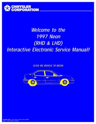
- 1. Welcome to the 1997 Neon (RHD & LHD) Interactive Electronic Service Manual! CLICK ON VEHICLE TO BEGIN tweddle litho: dom parts cdrom demo 09/96 page 4 <output:1248 ET 01/22/97>
- 2. GROUP TAB LOCATOR Introduction 0 Lubrication and Maintenance 2 Suspension 3 Differential and Driveline 5 Brakes 6 Clutch 7 Cooling 8A Battery 8B Starting 8C Charging System 8D Ignition System 8E Instrument Panel and Systems 8F Audio System 8G Horns 8H Vehicle Speed Control System 8J Turn Signal and Flashers 8K Windshield Wipers and Washers 8L Lamps 8M Restraint System 8N Electrically Heated Systems 8P Power Door Locks 8S Power Windows 8T Power Mirrors 8U Chime Warning/Reminder System 8W Wiring Diagrams 9 Engines 11 Exhaust System and Intake Manifold 13 Frame and Bumpers 14 Fuel System 19 Steering 21 Transaxle 22 Tires and Wheels 23 Body 24 Heating and Air Conditioning 25 Emission Control Systems
- 3. INTRODUCTION CONTENTS page page GENERAL INFORMATION BODY CODE EMBOSS . . . . . . . . . . . . . . . . . . . 2 FASTENER IDENTIFICATION . . . . . . . . . . . . . . . 4 INTERNATIONAL VEHICLE CONTROL AND DISPLAY SYMBOLS . . . . . . . . . . . . . . . . . . . . 3 METRIC SYSTEM . . . . . . . . . . . . . . . . . . . . . . . 7 STANDARD BODY DIMENSIONS . . . . . . . . . . . . 3 TORQUE REFERENCES . . . . . . . . . . . . . . . . . 10 VEHICLE IDENTIFICATION NUMBER . . . . . . . . . 1 VEHICLE SAFETY CERTIFICATION LABEL . . . . 2 GENERAL INFORMATION VEHICLE IDENTIFICATION NUMBER The Vehicle Identification Number (VIN) is located on the upper left corner of the instrument panel, near the left A-Pillar. The VIN consists of 17 charac- ters in a combination of letters and numbers that provide specific information about the vehicle (Fig. 1). Refer to VIN Code Decoding Chart. To protect the consumer from theft and possible fraud the manufacturer is required to include a Check Digit at the ninth position of the Vehicle Iden- tification Number. The check digit is used by the manufacturer and government agencies to verify the authenticity of the vehicle and official documenta- tion. The formula to use the check digit is not released to the general public. Fig. 1 Vehicle Identification Number INSTRUMENT PANEL A-PILLAR VIN LOCATION PL INTRODUCTION 1
- 4. VEHICLE SAFETY CERTIFICATION LABEL A vehicle safety certification label (Fig. 2) is attached to the rear facing of the driver’s door. This label indicates date of manufacture (month and year), Gross Vehicle Weight Rating (GVWR), Gross Axle Weight Rating (GAWR) front, Gross Axle Weight Rating (GAWR) rear and the Vehicle Identification Number (VIN). The Month, Day and Hour of manu- facture is also included. All communications or inquiries regarding the vehicle should include the Month-Day-Hour and Vehicle Identification Number. BODY CODE EMBOSS The Body Code Emboss is located in the engine compartment on the front of the right strut tower. There are two lines of information in the body code emboss. BODY CODE EMBOSS LINE 1 Line 1 contains the Vehicle Identification Number (VIN). Refer to Vehicle Identification Number (VIN) paragraph for proper breakdown of VIN code. BODY CODE EMBOSS LINE 2 DIGITS 1-3 —Paint Code Refer to Group 23, Body for paint information. DIGITS 4-7 —Trim Code Refer to Parts Catalog for more information. DIGITS 5-10 —Open DIGITS 11-14 —Vehicle Order Number VIN CODE DECODING POSITION INTERPRETATION CODE = DESCRIPTION 1 Country of Origin 1= United states 3= Mexico 2 Make B= Dodge P= Plymouth 3 Vehicle Type 3 = Passenger Car 4 Pass. Safety E = Active Restraints, Driver & Passenger Airbags 5 Car Line S = Neon / Neon Sport (sold in U.S./Canada) 6= Neon/Neon Sport (sold in Mexico) 6 Series 2 = Low Line 4 = High Line 6 = Sport 7 Body Style 2 = 2 Door Pillared Hardtop 7 = 4 Door Pillared Hardtop 8 Engine C = 2.0L 4 Cyl. 16V Y = 2.0L 4 Cyl. DOHC 9 Check Digit 10 Model Year V = 1997 11 Assembly Plant D = Belvidere T = Toluca 12 Thru 17 Vehicle Build Sequence Assembly Sequence Fig. 2 Vehicle Safety Certification Label 2 INTRODUCTION PL GENERAL INFORMATION (Continued)
- 5. STANDARD BODY DIMENSIONS INTERNATIONAL VEHICLE CONTROL AND DISPLAY SYMBOLS INTERNATIONAL VEHICLE CONTROL AND DISPLAY SYMBOLS The graphic symbols illustrated in the following chart (Fig. 3) are used to identify various instrument controls. The symbols correspond to the controls and displays that are located on the instrument panel. INTERIOR DIMENSIONS CAR BODY STYLE HEAD ROOM LEG ROOM SHOULDER ROOM HIP ROOM FRONT REAR FRONT REAR FRONT REAR FRONT REAR PL PL-42 1005 mm 928 mm 1080 mm 891 mm 1333 mm 1329 mm 1290 mm 1286 mm 39.6 in. 36.5 in. 42.5 in. 35.1 in. 52.5 in. 52.3 in. 50.8 in. 50.6 in. PL PL-22 1005 mm 928 mm 1080 mm 891 mm 1321 mm 1391 mm 1277 mm 1369 mm 39.6 in. 36.5 in. 42.5 in. 35.1 in. 52.0 in. 54.7 in. 50.3 in. 53.9 in. EXTERIOR DIMENSIONS CAR BODY STYLE WHEEL BASE FRONT TRACK REAR TRACK OVERALL LENGTH OVERALL WIDTH OVERALL HEIGHT MM/IN. MM/IN. MM/IN. MM/IN. MM/IN. MM/IN. PL PL-42 2642/104 1458/57.4 1458/57.4 4364/171.8 1708/67.2 1395/54.9 PL PL-22 2642/104 1458/57.4 1458/57.4 4364/171.8 1711/67.4 1395/54.9 INTERNATIONAL CONTROL AND DISPLAY SYMBOLS HIGH BEAM FOG LIGHTS HEADLIGHTS, PARKING LIGHTS, PANEL LIGHTS TURN SIGNAL HAZARD WARNING WINDSHIELD WASHER WINDSHIELD WIPER WINDSHIELD WIPER AND WASHER WINDSCREEN DEMISTING AND DEFROSTING VENTILATING FAN REAR WINDOW DEFOGGER REAR WINDOW WIPER REAR WINDOW WASHER FUEL ENGINE COOLANT TEMPER- ATURE BATTERY CHARGING CON- DITION ENGINE OIL SEAT BELT BRAKE FAILURE PARKING BRAKE FRONT HOOD REAR HOOD (TRUNK) HORN LIGHTER Fig. 3 PL INTRODUCTION 3 GENERAL INFORMATION (Continued)
- 6. FASTENER IDENTIFICATION FASTENER IDENTIFICATION THREAD IDENTIFICATION SAE and metric bolt/nut threads are not the same. The difference is described in the Thread Notation chart (Fig. 4). GRADE/CLASS IDENTIFICATION The SAE bolt strength grades range from grade 2 to grade 8. The higher the grade number, the greater the bolt strength. Identification is determined by the line marks on the top of each bolt head. The actual bolt strength grade corresponds to the number of line marks plus 2. The most commonly used metric bolt strength classes are 9.8 and 12.9. The metric strength class identification number is imprinted on the head of the bolt. The higher the class number, the greater the bolt strength. Some metric nuts are imprinted with a single-digit strength class on the nut face. Refer to the Fastener Identification and Fastener Strength Charts. Fig. 4 Thread Notation—SAE and Metric 4 INTRODUCTION PL GENERAL INFORMATION (Continued)
- 7. FASTENER IDENTIFICATION PL INTRODUCTION 5 GENERAL INFORMATION (Continued)
- 8. FASTENER STRENGTH HOW TO DETERMINE BOLT STRENGTH Hexagon head bolt Bolt head No. Stud bolt No mark No mark Hexagon flange bolt w/washer hexagon bolt No mark Grooved Hexagon head bolt Two protruding lines Hexagon flange bolt w/washer hexagon bolt Two protruding lines Welded bolt Hexagon head bolt Three protrud- ing lines Hexagon head bolt Four protruding lines 6 INTRODUCTION PL GENERAL INFORMATION (Continued)
- 9. METRIC SYSTEM WARNING: USE OF AN INCORRECT FASTENER MAY RESULT IN COMPONENT DAMAGE OR PER- SONAL INJURY. Figure art, specifications and torque references in this Service Manual are identified in metric and SAE format. During any maintenance or repair procedures, it is important to salvage metric fasteners (nuts, bolts, etc.) for reassembly. If the fastener is not salvage- able, a fastener of equivalent specification should be used. The metric system is based on quantities of one, ten, one hundred, one thousand and one million (Fig. 5). The following chart will assist in converting metric units to equivalent English and SAE units, or vise versa. Refer to the Conversion Chart to convert torque values listed in metric Newton- meters (N·m). Also, use the chart to convert between millimeters (mm) and inches (in.) CONVERSION FORMULAS AND EQUIVALENT VALUES Multiply By To Get Multiply By To Get in-lbs x 0.11298 = Newton-Meters (N·m) N·m x 8.851 = in-lbs ft-lbs x 1.3558 = Newton-Meters (N·m) N·m x 0.7376 = ft-lbs Inches Hg (60°F) x 3.377 = Kilopascals (kPa) kPa x 0.2961 = Inches Hg psi x 6.895 = Kilopascals (kPa) kPa x 0.145 = psi Inches x 25.4 = Millimeters (mm) mm x 0.03937 = Inches Feet x 0.3048 = Meters (M) M x 3.281 = Feet Yards x 0.9144 = Meters (M) M x 1.0936 = Yards Miles x 1.6093 = Kilometers (Km) Km x 0.6214 = Miles mph x 1.6093 = Kilometers/Hr. (Km/h) Km/h x 0.6214 = mph Feet/Sec. x 0.3048 = Meters/Sec. (M/S) M/S x 3.281 = Feet/Sec. Kilometers/Hr. x 0.27778 = Meters/Sec. (M/S) M/S x 3.600 = Kilometers/Hr. mph x 0.4470 = Meters/Sec. (M/S) M/S x 2.237 = mph COMMON METRIC EQUIVALENTS 1 Inch = 25 Millimeters 1 Cubic Inch = 16 Cubic Centimeters 1 Foot = 0.3 Meter 1 Cubic Foot = 0.03 Cubic Meter 1 Yard = 0.9 Meter 1 Cubic Yard = 0.8 Cubic Meter 1 Mile = 1.6 Kilometers Mega - (M) Million Deci - (D) Tenth Kilo - (K) Thousand Centi - (C) Hundredth Milli - (m) Thousandth Fig. 5 Metric Prefixes PL INTRODUCTION 7 GENERAL INFORMATION (Continued)
- 10. METRIC CONVERSION in-lbs to N·m N·m to in-lbs in-lb N·m in-lb N·m in-lb N·m in-lb N·m in-lb N·m N·m in-lb N·m in-lb N·m in-lb N·m in-lb N·m in-lb 2 .2260 42 4.7453 82 9.2646 122 13.7839 162 18.3032 .2 1.7702 4.2 37.1747 8.2 72.5792 12.2 107.9837 16.2 143.3882 4 .4519 44 4.9713 84 9.4906 124 14.0099 164 18.5292 .4 3.5404 4.4 38.9449 8.4 74.3494 12.4 109.7539 16.4 145.1584 6 .6779 46 5.1972 86 9.7165 126 14.2359 166 18.7552 .6 5.3107 4.6 40.7152 8.6 76.1197 12.6 111.5242 16.6 146.9287 8 .9039 48 5.4232 88 9.9425 128 14.4618 168 18.9811 .8 7.0809 4.8 42.4854 8.8 77.8899 12.8 113.2944 16.8 148.6989 10 1.1298 50 5.6492 90 10.1685 130 14.6878 170 19.2071 1 8.8511 5 44.2556 9 79.6601 13 115.0646 17 150.4691 12 1.3558 52 5.8751 92 10.3944 132 14.9138 172 19.4331 1.2 10.6213 5.2 46.0258 9.2 81.4303 13.2 116.8348 17.2 152.2393 14 1.5818 54 6.1011 94 10.6204 134 15.1397 174 19.6590 1.4 12.3916 5.4 47.7961 9.4 83.2006 13.4 118.6051 17.4 154.0096 16 1.8077 56 6.3270 96 10.8464 136 15.3657 176 19.8850 1.6 14.1618 5.6 49.5663 9.6 84.9708 13.6 120.3753 17.6 155.7798 18 2.0337 58 6.5530 98 11.0723 138 15.5917 178 20.1110 1.8 15.9320 5.8 51.3365 9.8 86.7410 13.8 122.1455 17.8 157.5500 20 2.2597 60 6.7790 100 11.2983 140 15.8176 180 20.3369 2 17.7022 6 53.1067 10 88.5112 14 123.9157 18 159.3202 22 2.4856 62 7.0049 102 11.5243 142 16.0436 182 20.5629 2.2 19.4725 6.2 54.8770 10.2 90.2815 14.2 125.6860 18.5 163.7458 24 2.7116 64 7.2309 104 11.7502 144 16.2696 184 20.7889 2.4 21.2427 6.4 56.6472 10.4 92.0517 14.4 127.4562 19 168.1714 26 2.9376 66 7.4569 106 11.9762 146 16.4955 186 21.0148 2.6 23.0129 6.6 58.4174 10.6 93.8219 14.6 129.2264 19.5 172.5970 28 3.1635 68 7.6828 108 12.2022 148 16.7215 188 21.2408 2.8 24.7831 6.8 60.1876 10.8 95.5921 14.8 130.9966 20 177.0225 30 3.3895 70 7.9088 110 12.4281 150 16.9475 190 21.4668 3 26.5534 7 61.9579 11 97.3624 15 132.7669 20.5 181.4480 32 3.6155 72 8.1348 112 12.6541 152 17.1734 192 21.6927 3.2 28.3236 7.2 63.7281 11.2 99.1326 15.2 134.5371 21 185.8736 34 3.8414 74 8.3607 114 12.8801 154 17.3994 194 21.9187 3.4 30.0938 7.4 65.4983 11.4 100.9028 15.4 136.3073 22 194.7247 36 4.0674 76 8.5867 116 13.1060 156 17.6253 196 22.1447 3.6 31.8640 7.6 67.2685 11.6 102.6730 15.6 138.0775 23 203.5759 38 4.2934 78 8.8127 118 13.3320 158 17.8513 198 22.3706 3.8 33.6342 7.8 69.0388 11.8 104.4433 15.8 139.8478 24 212.4270 40 4.5193 80 9.0386 120 13.5580 160 18.0773 200 22.5966 4 35.4045 8 70.8090 12 106.2135 16 141.6180 25 221.2781 ft-lbs to N·m N·m to ft-lbs ft-lb N·m ft-lb N·m ft-lb N·m ft-lb N·m ft- lb N·m N·m ft-lb N·m ft-lb N·m ft-lb N·m ft-lb N·m ft-lb 1 1.3558 21 28.4722 41 55.5885 61 82.7049 81 109.8212 1 .7376 21 15.9888 41 30.2400 61 44.9913 81 59.7425 2 2.7116 22 29.8280 42 56.9444 62 84.0607 82 111.1770 2 1.4751 22 16.2264 42 30.9776 62 45.7289 82 60.4801 3 4.0675 23 31.1838 43 58.3002 63 85.4165 83 112.5328 3 2.2127 23 16.9639 43 31.7152 63 46.4664 83 61.2177 4 5.4233 24 32.5396 44 59.6560 64 86.7723 84 113.8888 4 2.9502 24 17.7015 44 32.4527 64 47.2040 84 61.9552 5 6.7791 25 33.8954 45 61.0118 65 88.1281 85 115.2446 5 3.6878 25 18.4391 45 33.1903 65 47.9415 85 62.6928 6 8.1349 26 35.2513 46 62.3676 66 89.4840 86 116.6004 6 4.4254 26 19.1766 46 33.9279 66 48.6791 86 63.4303 7 9.4907 27 36.6071 47 63.7234 67 90.8398 87 117.9562 7 5.1629 27 19.9142 47 34.6654 67 49.4167 87 64.1679 8 10.8465 28 37.9629 48 65.0793 68 92.1956 88 119.3120 8 5.9005 28 20.6517 48 35.4030 68 50.1542 88 64.9545 9 12.2024 29 39.3187 49 66.4351 69 93.5514 89 120.6678 9 6.6381 29 21.3893 49 36.1405 69 50.8918 89 65.6430 10 13.5582 30 40.6745 50 67.7909 70 94.9073 90 122.0236 10 7.3756 30 22.1269 50 36.8781 70 51.6293 90 66.3806 11 14.9140 31 42.0304 51 69.1467 71 96.2631 91 123.3794 11 8.1132 31 22.8644 51 37.6157 71 52.3669 91 67.1181 12 16.2698 32 43.3862 52 70.5025 72 97.6189 92 124.7352 12 8.8507 32 23.6020 52 38.3532 72 53.1045 92 67.8557 13 17.6256 33 44.7420 53 71.8583 73 98.9747 93 126.0910 13 9.5883 33 24.3395 53 39.0908 73 53.8420 93 68.5933 14 18.9815 34 46.0978 54 73.2142 74 100.3316 94 127.4468 14 10.3259 34 25.0771 54 39.8284 74 54.5720 94 69.3308 15 20.3373 35 47.4536 55 74.5700 75 101.6862 95 128.8026 15 11.0634 35 25.8147 55 40.5659 75 55.3172 95 70.0684 16 21.6931 36 48.8094 56 75.9258 76 103.0422 96 130.1586 16 11.8010 36 26.5522 56 41.3035 76 56.0547 96 70.8060 17 23.0489 37 50.1653 57 77.2816 77 104.3980 97 131.5144 17 12.5386 37 27.2898 57 42.0410 77 56.7923 97 71.5435 18 24.4047 38 51.5211 58 78.6374 78 105.7538 98 132.8702 18 13.2761 38 28.0274 58 42.7786 78 57.5298 98 72.2811 19 25.7605 39 52.8769 59 79.9933 79 107.1196 99 134.2260 19 14.0137 39 28.7649 59 43.5162 79 58.2674 99 73.0187 20 27.1164 40 54.2327 60 81.3491 80 108.4654 100 135.5820 20 14.7512 40 29.5025 60 44.2537 80 59.0050 100 73.7562 8 INTRODUCTION PL GENERAL INFORMATION (Continued)
- 11. in. to mm mm to in. in. mm in. mm in. mm in. mm in. mm mm in. mm in. mm in. mm in. mm in. .01 .254 .21 5.334 .41 10.414 .61 15.494 .81 20.574 .01 .00039 .21 .00827 .41 .01614 .61 .02402 .81 .03189 .02 .508 .22 5.588 .42 10.668 .62 15.748 .82 20.828 .02 .00079 .22 .00866 .42 .01654 .62 .02441 .82 .03228 .03 .762 .23 5.842 .43 10.922 .63 16.002 .83 21.082 .03 .00118 .23 .00906 .43 .01693 .63 .02480 .83 .03268 .04 1.016 .24 6.096 .44 11.176 .64 16.256 .84 21.336 .04 .00157 .24 .00945 .44 .01732 .64 .02520 .84 .03307 .05 1.270 .25 6.350 .45 11.430 .65 16.510 .85 21.590 .05 .00197 .25 .00984 .45 .01772 .65 .02559 .85 .03346 .06 1.524 .26 6.604 .46 11.684 .66 16.764 .86 21.844 .06 .00236 .26 .01024 .46 .01811 .66 .02598 .86 .03386 .07 1.778 .27 6.858 .47 11.938 .67 17.018 .87 22.098 .07 .00276 .27 .01063 .47 .01850 .67 .02638 .87 .03425 .08 2.032 .28 7.112 .48 12.192 .68 17.272 .88 22.352 .08 .00315 .28 .01102 .48 .01890 .68 .02677 .88 .03465 .09 2.286 .29 7.366 .49 12.446 .69 17.526 .89 22.606 .09 .00354 .29 .01142 .49 .01929 .69 .02717 .89 .03504 .10 2.540 .30 7.620 .50 12.700 .70 17.780 .90 22.860 .10 .00394 .30 .01181 .50 .01969 .70 .02756 .90 .03543 .11 2.794 .31 7.874 .51 12.954 .71 18.034 .91 23.114 .11 .00433 .31 .01220 .51 .02008 .71 .02795 .91 .03583 .12 3.048 .32 8.128 .52 13.208 .72 18.288 .92 23.368 .12 .00472 .32 .01260 .52 .02047 .72 .02835 .92 .03622 .13 3.302 .33 8.382 .53 13.462 .73 18.542 .93 23.622 .13 .00512 .33 .01299 .53 .02087 .73 .02874 .93 .03661 .14 3.556 .34 8.636 .54 13.716 .74 18.796 .94 23.876 .14 .00551 .34 .01339 .54 .02126 .74 .02913 .94 .03701 .15 3.810 .35 8.890 .55 13.970 .75 19.050 .95 24.130 .15 .00591 .35 .01378 .55 .02165 .75 .02953 .95 .03740 .16 4.064 .36 9.144 .56 14.224 .76 19.304 .96 24.384 .16 .00630 .36 .01417 .56 .02205 .76 .02992 .96 .03780 .17 3.318 .37 9.398 .57 14.478 .77 19.558 .97 24.638 .17 .00669 .37 .01457 .57 .02244 .77 .03032 .97 .03819 .18 4.572 .38 9.652 .58 14.732 .78 19.812 .98 24.892 .18 .00709 .38 .01496 .58 .02283 .78 .03071 .98 .03858 .19 4.826 .39 9.906 .59 14.986 .79 20.066 .99 25.146 .19 .00748 .39 .01535 .59 .02323 .79 .03110 .99 .03898 .20 5.080 .40 10.160 .60 15.240 .80 20.320 1.00 25.400 .20 .00787 .40 .01575 .60 .02362 .80 .03150 1.00 .03937 PL INTRODUCTION 9 GENERAL INFORMATION (Continued)
- 12. TORQUE REFERENCES Individual Torque Charts appear at the end of many Groups. Refer to the Standard Torque Specifi- cations Chart for torque references not listed in the individual torque charts. TORQUE SPECIFICATIONS SPECIFIED TORQUE FOR STANDARD BOLTS Class Diameter mm Pitch mm Specified torque Hexagon head bolt Hexagon flange bolt N·m kgf-cm ft-lbf N·m kgf-cm ft-lbf 6 1 5 55 48 in.-lbf 6 60 52 in.-lbf 8 1.25 12.5 130 9 14 145 10 4T 10 1.25 26 260 19 29 290 21 12 1.25 47 480 35 53 540 39 14 1.5 74 760 55 84 850 61 16 1.5 115 1,150 83 — — — 6 1 6.5 65 56 in.-lbf 7.5 75 65 in.-lbf 8 1.25 15.5 160 12 17.5 175 13 5T 10 1.25 32 330 24 36 360 26 12 1.25 59 600 43 65 670 48 14 1.5 91 930 67 100 1,050 76 16 1.5 140 1,400 101 — — — 6 1 8 80 69 in.-lbf 9 90 78 in.-lbf 8 1.25 19 195 14 21 210 15 6T 10 1.25 39 400 29 44 440 32 12 1.25 71 730 53 80 810 59 14 1.5 110 1,100 80 125 1,250 90 16 1.5 170 1,750 127 — — — 6 1 10.5 110 8 12 120 9 8 1.25 25 260 19 28 290 21 7T 10 1.25 52 530 38 58 590 43 12 1.25 95 970 70 105 1,050 76 14 1.5 145 1,500 108 165 1,700 123 16 1.5 230 2,300 166 — — — 8 1.25 29 300 22 33 330 24 8T 10 1.25 61 620 45 68 690 50 12 1.25 110 1,100 80 120 1,250 90 8 1.25 34 340 25 37 380 27 9T 10 1.25 70 710 51 78 790 57 12 1.25 125 1,300 94 140 1,450 105 8 1.25 38 390 28 42 430 31 10T 10 1.25 78 800 58 88 890 64 12 1.25 140 1,450 105 155 1,600 116 8 1.25 42 430 31 47 480 35 11T 10 1.25 87 890 64 97 990 72 12 1.25 155 1,600 116 175 1,800 130 10 INTRODUCTION PL GENERAL INFORMATION (Continued)
- 13. Thank you very much for your reading. Please Click Here. Then Get COMPLETE MANUAL. NO WAITING NOTE: If there is no response to click on the link above, please download the PDF document first and then click on it.
- 14. INTRODUCTION CONTENTS page page GENERAL INFORMATION E-MARK LABEL . . . . . . . . . . . . . . . . . . . . . . . . . 1 MANUFACTURER PLATE . . . . . . . . . . . . . . . . . . 2 VEHICLE IDENTIFICATION NUMBER . . . . . . . . . 1 GENERAL INFORMATION VEHICLE IDENTIFICATION NUMBER The Vehicle Identification Number (VIN) can be viewed through the windshield at the upper left cor- ner of the instrument panel next to the left A-pillar on left-hand-drive vehicles (Fig. 1) and through the windshield at the upper right corner of the instru- ment panel next to the right A-pillar on right-hand- drive vehicles (Fig. 2). The VIN consists of 17 characters in a combination of letters and numbers that provide specific information about the vehicle. Refer to the VIN Decoding Information Table to interpret VIN code. VIN CHECK DIGIT To protect the consumer from theft and possible fraud the manufacturer is required to include a check Digit at the ninth position of the VIN. The check digit is used by the manufacturer and government agencies to verify the authenticity of the vehicle and official documentation. The formula to use the check digit is not released to the general public. E-MARK LABEL An E-mark Label (Fig. 3) is located on the rear shut face of the driver’s door. The label contains the following information: • Date of Manufacture • Month-Day-Hour (MDH) • Vehicle Identification Number (VIN) • Country Codes • Regulation Number • Regulation Amendment Number • Approval Number Fig. 1 VIN Plate Location — LHD Fig. 2 VIN Plate Location — RHD Fig. 3 E-Mark Label PL INTRODUCTION 1
- 15. MANUFACTURER PLATE The Manufacturer Plate (Fig. 4) is located in the engine compartment on the right side of the radiator closure panel crossmember adjacent. The plate con- tains five lines of information: 1. Vehicle Identification Number (VIN) 2. Gross Vehicle Mass (GVM) 3. Gross Train Mass (GTM) 4. Gross Front Axle Rating (GFAR) 5. Gross Rear Axle Rating (GRAR) VIN DECODING INFORMATION POSITION INTERPRETATION CODE = DESCRIPTION 1 Country of origin 1 = United States 2 Make C = Chrysler 3 Vehicle Type 3 = Passenger Car 4 Passenger Safety E = Active Restraints, Driver and Passenger Airbags 5 Car Line S = Neon 6 Series M = DD5 5-Speed Manual Transmission A = 3-Speed Automatic Transmission 7 Body Style 7 = 4 Door Pillared Hardtop 8 Engine C = 2.0L 4 Cyl. 16V SOHC 9 Check Digit See explanation in this section. 10 Model Year V = 1997 11 Assembly Plant D = Belvedere Assembly 12 Build Sequence 6 Digit number assigned by assembly plant Fig. 4 Manufacturer Plate 2 INTRODUCTION PL GENERAL INFORMATION (Continued)
- 16. LUBRICATION AND MAINTENANCE CONTENTS page page GENERAL INFORMATION . . . . . . . . . . . . . . . . . . 1 JUMP STARTING, TOWING AND HOISTING . . . 7 MAINTENANCE SCHEDULES . . . . . . . . . . . . . . . 3 GENERAL INFORMATION INDEX page page GENERAL INFORMATION CLASSIFICATION OF LUBRICANTS . . . . . . . . . . 1 FLUID CAPACITIES . . . . . . . . . . . . . . . . . . . . . . 2 INTERNATIONAL SYMBOLS . . . . . . . . . . . . . . . 1 INTRODUCTION . . . . . . . . . . . . . . . . . . . . . . . . 1 PARTS AND LUBRICANT RECOMMENDATIONS . . . . . . . . . . . . . . . . . . 1 GENERAL INFORMATION INTRODUCTION Service and maintenance procedures for compo- nents and systems listed in Schedule—A or B can be found by using the Group Tab Locator index at the front of this manual. If it is not clear which group contains the information needed, refer to the index at the back of this manual. There are two maintenance schedules that show proper service based on the conditions that the vehi- cle is subjected to. Schedule— A , lists scheduled maintenance to be performed when the vehicle is used for general trans- portation. Schedule— B , lists maintenance intervals for vehi- cles that are operated under the conditions listed at the beginning of the Maintenance Schedule section. Use the schedule that best describes your driving conditions. Where time and mileage are listed, follow the interval that occurs first. PARTS AND LUBRICANT RECOMMENDATIONS When service is required, Chrysler Corporation recommends that only Mopart brand parts, lubri- cants and chemicals be used. Mopar provides the best engineered products for servicing Chrysler Cor- poration vehicles. INTERNATIONAL SYMBOLS Chrysler Corporation uses international symbols to identify engine compartment lubricant and fluid inspection and fill locations (Fig. 1). Fig. 1 International Symbols ENGINE OIL AUTOMATIC TRANSMISSION FLUID ENGINE COOLANT BRAKE FLUID POWER STEERING FLUID WINDSHIELD WASHER FLUID PL LUBRICATION AND MAINTENANCE 0 - 1